
Related Manuals for Unitor UPC 1041


Summary of Contents for Unitor UPC 1041
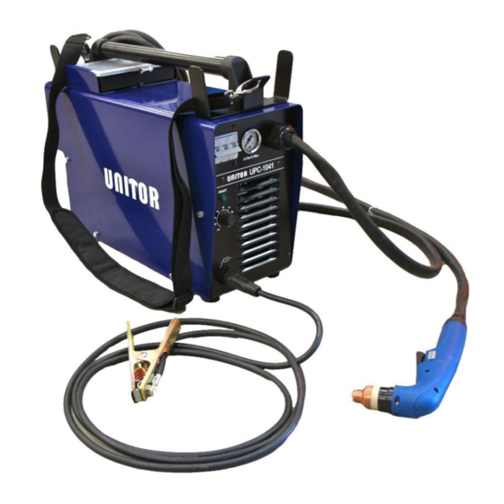
- Page 1 Instruction manual UPC 1041 Air Plasma Cutter Revision date: 14-11-30 Page 1 of 42...
- Page 2 CONTENTS 1. TECHNICAL DATA 2. INSTALLATION 3. OPERATING INSTRUCTIONS 4. TORCH PARTS 5. MAINTENANCE 6. TROUBLE SHOOTING 7. SAFETY INSTRUCTIONS 8. SERVICE SECTION UPC-1041 Air Plasma Cutter 192-404100 delivery consist of : Remarks : Plug for primary cable and air hose is not supplied as this will depend on the connections available onboard.
- Page 3 1 TECHNICAL DATA Power supply 440 V *, 3~50/60 Hz Mains fuse min 20 A slow blow Maximum power 14,7 kVA Process power 120 V, 20-100 A Duty cycle @ 40°C 35% @ 100 A 60% @ 80A 100% @ 60A Power factor 0,95 Open circuit voltage...
- Page 4 3 OPERATING INSTRUCTIONS Check that the machine has been properly connected to power supply and compressed air according to chapter 2, INSTALLATION. Check that the torch is fitted with appropriate consumables for the job at hand. Connect the return clamp directly onto the work piece, ensuring that a good contact is obtained. If necessary, clean the surface from paint, rust, dirt, etc.
- Page 5 Piercing Rest the contact drag shield on the work piece at 45° angle Press the trigger-switch on the torch handle. Air will flow for one second before the pilot arc strikes. After cutting arc starts, slowly and in one smooth movement, straighten torch back up until 90°...
- Page 6 When the machine is not in use or is only working at long intervals, switch off the machine. It contains mechanical components that should not be exposed to unnecessary wear. It also protects against accidental firing the pilot arc. 4 TORCH PARTS Revision date: 14-11-30 Page 6 of 42...
- Page 7 Pos.no Description Product no UPC-1041 Plasma cutter complete with 6m cable 192 - 404100 Torch PTA 121 with 6m cable and drag shield for UPC- 192 - 404114 1041 (incl. w. machine) 192 – 404115 Torch PTA 121 with 15 m cable and drag shield for UPC-1041 (optional) 1 (not Hose assembly for PTA 121 torch 6m, excl.
-
Page 8: Maintenance
5. MAINTENANCE DAILY Inspect and, if necessary, change the torch consumable parts. Note: Electrode and nozzle must be changed at regular intervals, as a general guideline after 2 hours continues use, or after 200 starts. Always replace the electrode if the center has a pit more than 2 mm (1/16” deep). Replace the nozzle if the opening is deformed or clearly oversized. -
Page 9: Trouble Shooting
6. TROUBLE SHOOTING. Thermal overload. If the air pressure is correct but the green ready lamp is not lit the power source is overheated and needs to cool down before it can be used again. Let the machine cool down while switched on until the ready lamp lights up. -
Page 10: Safety Instructions
7. SAFETY INSTRUCTIONS All endangerments through plasma cutting are related with the process itself. Endangerments may occur due to: - High contact voltage - HV ignition - Electromagnetic interferences - Heat and light radiation - Gases, fumes and smoke - Noise - Hot metal and spatter - Handling of pressure cylinders The Plasma Cutting Machine has been developed in conformity with following standards:... - Page 11 Recommendations to classify the environment (EN 60974-10): Before the installation takes place the user has to evaluate the environment for electromagnetic problems and to take into consideration: Other mains supplies, control cables, signal and telecommunication lines along, above, below or beside the installation.
-
Page 12: Service Section
8. SERVICE SECTION Fault finding: 8.1 Check overvoltage varistors Disconnect the machine from mains power supply. 1. Disconnect the incoming leads from the E5 EMC-filter. Make a visual inspection of the three varistors if any looks damaged then the machine has been connected to a voltage exceeding the approved 440VAC. - Page 13 8.2 Check the E5 EMC-Filter PCB. Verify that the machine is disconnected from the mains power supply. 1. Reconnect the incoming leads to the E5 EMC-Filter. 2. Measure the three phases in the incoming socket with resistance measurement. Correct value is approx. 240 k ohm, if the value is low or a short is measured then replace the E5 EMC-Filter.
-
Page 14: Revision Date: 14
Cont. 8.2 Check the EMC-Filter 3. Measure between W, V, and U, on the incoming and outgoing side on the E5 EMC-Filter with a buzzer or resistance measurement. If no connection, then replace the E5 EMC-Filter. Note that the placement of V and W is shifted on the outgoing side. Revision date: 14-11-30 Page 14 of 42... - Page 15 8.3 Check the B1 Main switch. Verify that the machine is disconnected from the mains supply. 1. Turn on B1 main switch. Remove the fuse from the T1 Control transformer. 2. Measure between the cables 11, 21 and 31 and the three phases on the incoming side on the main switch with a resistance or summer measurement.
- Page 16 8.4 Check the D5 main rectifier. Verify that the machine is disconnected from the mains supply. 1. Measure with instrument set to diode test, place the positive probe on cable 74 and the negative probe on cable 11, 21 and 31. Correct value is approx 0.5V this can differ slightly between instruments.
- Page 17 8.5 Check the E1 Primary switching PCB. Verify that the machine is disconnected from the mains supply. Note. These measurement are all made at room temperature 20°C, if the machine is used recently the values may differ. 1. Disconnect cable 73 and 74 from the D5 main rectifier. 2.
- Page 18 Cont. 8.5 Check the E1 Primary switching PCB. 4. Measure between pin 1-2 and 7-8 with the meter set to diode test and the positive probe on the red lead. Correct value is approx. 1.15. This value may differ a bit between different instruments but if very low or a short is measured on one pair then replace the E1 primary PCB.
- Page 19 8.6 Check the E4 Secondary PCB. Note. These measurement are all made at room temperature 20°C, if the machine is used recently the values may differ. 1. Disconnect one of the main transformer leads and one of the choke leads. 2.
- Page 20 Cont. 8.6 Check the E4 Secondary PCB. 5. Measure between TS1_B and TS1_C, with diode test and the positive probe on TS1_C. Correct value is OL or unlimited. If a low value or a short is measured replace the transistor module TS1.
- Page 21 8.7 Check the K1 pressure switch and K2-4 thermostat. 1. Turn the knob on the pressure regulator CCW to its lowest setting. Connect air at 6-8 bar to the regulator. Turn the knob on the regulator CW to increase pressure setting while you measure between cable 46 and 66 on the K1 pressure switch with resistance or buzzer measurement, at approx.
- Page 22 8.8 Check supply and system voltage. Connect the machine to mains supply. 1. Check the incoming voltage between all three phases. Correct value is 400 or 440VAC depending on the supply voltage. If one phase is missing or low check the mains supply fuses. Switch on the machine with B1 main switch.
- Page 23 Cont. 8.8 Check supply and system voltage 3. Check the voltages on the T1 Control transformer, between 0 and 230 on the primary side. If low or not existing check the fuse on the control transformer. If fuse is undamaged replace the control transformer.
- Page 24 Cont. 8.8 Check supply and system voltage 7. Measure the voltage between TS1_A and TS1_D on the E4 Secondary PCB. Correct value is 10VDC, if low or missing replace the E4 Secondary PCB and TS1. 8. Measure the relay inside the copper winding, between point J1 and J2. Correct value is 18VDC.
- Page 25 8.9 Check the E3 Control & ignition PCB. 1. Disconnect the pulse leads from the E2 PWM PCB connector A4. Switch on the machine with B1 main switch. 2. Check the fuse on the E3 Ignition & control PCB with buzzer or resistance measurement. If fuse is broken replace the fuse and go to step 3, if fuse breaks again replace E3 Ignition &control PCB.
- Page 26 8.10 Check the E2 PWM PCB. 1. Disconnect the pulse leads from the E2 PWM PCB connector A4. Switch on the machine with B1 main switch. 2. Check the Fuse on the E2 PWM PCB with buzzer or resistance measurement. If the fuse is broken try replacing it with a new and switch on the machine.
- Page 27 8.11 Check open circuit voltage. 1. Remove jumper J1 from the E3 ignition & control pcb. Switch on the machine with B1. 2. Measure between P and minus (-) on the E4 secondary PCB with a DC voltage measurement. Press torch trigger, after approx. 1sec you should get voltage. This voltage will disappear after approx. 3seconds and its then necessary to release and press torch trigger again.
- Page 28 8.12 Check E3 Control & Ignition PCB sequence. Correct sequence: 1. Not active: None off the leds are lit 2. Pre flow: Press torch trigger, D17 lights up indicating pre flow, gas starts to flow through the system 3. Pilot arc: After about 1sec D16 lights up indicating that the PWM PCB should start to send out pulses to the primary PCB, and that the ignition pulses to the ignition transformer should start.
- Page 29 Cont. 8.12 Check E3 Control & Ignition PCB. 4. Main arc: When the pilot arc gets in contact with the cutting material D15 and D25 lights up indicating that the signal for contact with material has been detected, the E3 Control & ignition PCB is activating the cutting flow, switching off pilot transistor and increasing current from pilot current to cutting current.
- Page 30 8.13 Active Fan Control check. 1. When switching on the machine with the B1 switch the fan should start running and LED D23 and D28 should light up. After approx. 5min the fan should switch off and D23 and D28 should go out. 2.
- Page 31 Torch change. Disconnect the machine from main power supply. Remove handle and cover. Disconnect the trigger leads. Disconnect the pilot lead by removing the M6 nut from the pilot lead connector. Disconnect the Current/air lead by unscrewing the ¼” nut from the current connector. Revision date: 14-11-30 Page 31 of 42...
- Page 32 Loosen the cable restraints lock nut and pull out the torch leads. Insert the leads on the new torch through the cable restraint., Connect the ¼” nut on the Current/air lead to the current connector. Take care not to over tighten. Connect the pilot lead to the M6 pilot lead connector with the M6 nut and locking washer.
- Page 33 Connect the trigger leads to the trigger connector. Polarity is not important. Tighten the cable restraints locking nut. Take care not to over tighten since this may hinder airflow. Replace cover and handle. Revision date: 14-11-30 Page 33 of 42...
- Page 34 Revision date: 14-11-30 Page 34 of 42...
- Page 35 Revision date: 14-11-30 Page 35 of 42...
- Page 36 Revision date: 14-11-30 Page 36 of 42...
- Page 37 Revision date: 14-11-30 Page 37 of 42...
- Page 38 Revision date: 14-11-30 Page 38 of 42...
- Page 39 Notes Revision date: 14-11-30 Page 39 of 42...
- Page 40 Notes Revision date: 14-11-30 Page 40 of 42...
- Page 41 Revision date: 14-11-30 Page 41 of 42...
- Page 42 Fraser/surrey Gaspe Gros Caouna Halifax Hamilton Harbour Grace Holyrood Kitimat Long Pond Marytown Montreal Nanaimo New Westminster Bc Instruction manual Pictou/halifax Pointe Aux Pic.quebec Port Alfred Port Cartier Port Colborne Port Hawkesbury Port Mellon Port Moody Port Of Quebec Port Weller Powell River Prince Rupert Roberts Bank Saint John Sarnia, Ontario Sept Iles Seven Islands Sorel Souris/ halifax Squamish St.