
Related Manuals for Intel RX87Q


Summary of Contents for Intel RX87Q
- Page 1 RX87Q Intel® Q87 μATX Motherboard Supports 22nm Generation Core i7/i5/i3, Pentium® μATX Motherboard User’s Manual Edition 1.0 – Oct, 2013...
- Page 2 FCC Statement THIS DEVICE SUPPORTS PART 15 FCC RULES. OPERATION IS SUBJECT TO THE FOLLOWING TWO CONDITIONS: (1) THIS DEVICE MAY NOT CAUSE HARMFUL INTERFERENCE. (2) THIS DEVICE MUST ACCEPT ANY INTERFERENCE RECEIVED INCLUDING INTERFERENCE THAT MAY CAUSE UNDESIRED OPERATION. THIS EQUIPMENT HAS BEEN TESTED AND FOUND TO COMPLY WITH THE LIMITS FOR A CLASS "A"...
- Page 3 Disclaimer BCM Advanced Research reserves the right to make changes, without notice, to any product, including circuits and/or software described or contained in this manual in order to improve design and/or performance. BCM Advanced Research assumes no responsibility or liability for the use of the described product(s), conveys no license or title under any patent, copyright, or masks work rights to these products, and makes no representations or warranties that these products are free from patent, copyright, or mask work right infringement, unless otherwise specified.
-
Page 4: Bcm Customer Services
A Message to the Customer BCM Customer Services Each and every BCM product is built to the most exacting specifications to ensure reliable performance in the harsh and demanding conditions typical of industrial environments. Whether your new BCM device is destined for the laboratory or the factory floor, you can be assured that your product will provide the reliability and ease of operation for which the name BCM has come to be known. -
Page 5: Product Warranty
Product Warranty BCM warrants to you, the original purchaser, that each of its products will be free from defects in materials and workmanship during warranty period. This warranty does not apply to any products which have been repaired or altered by persons other than repair personnel authorized by BCM, or which have been subject to misuse, abuse, accident or improper installation. - Page 6 This manual describes in detail the BCM RX87Q Main board. We strongly recommend that you study this manual carefully before attempting to interface with RX87Q or change the standard configurations. Whilst all the necessary information is available in this manual we would recommend that unless you are confident, you contact your supplier for guidance.
-
Page 7: Table Of Contents
Contents Chapter 1: System Setup ....................Welcome! ............................11 Packing Contents .......................... 11 Features System Block Diagram ....................12 1.3.1 Product Highlights ......................... 13 Before you proceed ........................14 Mainboard Overview ........................15 1.5.1 Placement Direction ........................15 1.5.2 Mounting Holes ..........................16 1.5.3 Onboard LEDs .......................... - Page 8 1.10.3 Chassis Intrusion Switch Connector: JCASE1 ................40 1.10.4 Front Panel Audio Connector: FPAUD1 ..................40 1.10.5 Amplifier Connector: JAMP1 ......................41 1.10.6 Front USB2.0 Headers: USB45, USB67, USB89, USB1011, USB1213 ........42 1.10.7 Serial Port Connectors: COM1, COM2, COM3, COM4 ..............42 1.10.8 LPT Port Connector: LPT1 ......................
- Page 9 Standard 1Gb, 2Gb and 4Bb Technologies and addressing are supported for x8 derives Display Intel® GMA HD (Must use Intel Processor that provides “Intel HD Graphics” feature) SATA 6 x SATA III connectors supports Data Transfer rates 6.0Gb/s, 3.0Gb/s and 1.5Gb/s...
- Page 10 Expansion Slots PCI-E 1 x PCI-E x 16 slot 1 x PCI-E x 4 slot 1 x PCI-E x 1 slot 1 x PCI slot Onboard I/O Headers SATA 6 x Std. SATA Connectors 5 x USB Headers (10 ports on headers) RS232 6 x Headers 1 x Header...
-
Page 11: Chapter 1: System Setup
• 1 x RX87Q • Cable • 2 x Serial ATA Cable • 2 x COM port Cable • Accessories • 1 x RX87Q I/O Shield • Drivers • Drivers is available for download at BCM website at WWW.BCMCOM.COM • Documentation •... -
Page 12: Features System Block Diagram
1.3 Features RX87Q block Diagram... -
Page 13: Product Highlights
LGA1150 package. • Intel® Q87 Express Chipset The Intel® Q87 PCH provides all business with more effective costs management, safer computing environment, and deploys more responsive PCs. • DDR3 Memory Support The mainboard supports DDR3 memory that features data transfer rates of 1333/ 1600MHz to meet the higher bandwidth requirements of the latest 3D graphics, multimedia, and Internet applications. -
Page 14: Before You Proceed
1.4 Before you proceed Take note of the following precautions before you install mainboard components or change any mainboard settings. • Unplug the power cord from the wall socket before touching any component inside the system. • Use a grounded wrist strap or touch a safely grounded object or to a metal object, such as the power supply case, before handling components to avoid damaging them due to static electricity. -
Page 15: Mainboard Overview
1.5 Mainboard Overview Before you install the mainboard, study the configuration of your chassis to ensure that the mainboard fits into it. Make sure to unplug the power cord before installing or removing the mainboard. Failure to do so can cause you physical injury and damage mainboard components. 1.5.1 Placement Direction When installing the mainboard, make sure that you place it into the chassis in the correct orientation. -
Page 16: Mounting Holes
1.5.2 Mounting Holes Place the screws into the mounting holes indicated by red squares to secure the mainboard to the chassis. Do not over-tighten the screws! Doing so may damage the mainboard. -
Page 17: Onboard Leds
1.5.3 Onboard LEDs The mainboard comes with a “Power On LED” (green) to indicate the system power status. When power cable is connect to the power source. The “Power LED” lights will be on to indicate that the system has standby power. -
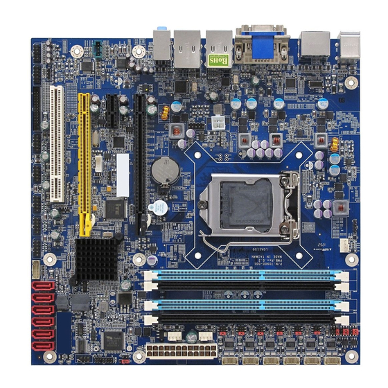
Page 18: Mainboard Layout
1.5.4 Mainboard Layout • Back Panel:... -
Page 19: Layout Content List
1.5.5 Layout Content List • 1.5.5.1 Slots Label Function Note Page DIMM1 240-pin DIMM slot 1 1. If there is only one memory module being installed in the system, install it on this slot first. 2. If there are only two memory modules being installed in the system, install these 2 modules on “DIMM1”... -
Page 20: Internal Headers
• 1.5.5.3 Internal Headers Label Function Note Page PWR1 ATX Power Connector 2 x 2 header ATX1 ATX Power Connector 12 x 2 header SATA1 Serial ATA Connectors 1~6 7-pin header SATA2 SATA3 SATA4 SATA5 SATA6 CPU_FAN (CN7) CPU Fan Connector 4 x 1 wafer, pitch 2.54mm CHA_FAN1 (CN3) Chassis Fan Connector... -
Page 21: Back Panel Connectors
• 1.5.5.4 Back Panel Connectors Label Function Note Page KBMS PS/2 keyboard and mouse 6-pin Mini-Din VGA/ DVI VGA Connector x 1 D-sub 15-pins, female DVI Connector x 1 Dual Link DVI-D; 24-pins DP1/ DP2 Display Port x 2 (COM1/ COM2) LAN1/ LAN2 RJ-45 Ethernet Connector x 2 USB3.0 Connector x 4... -
Page 22: Central Processing Unit (Cpu)
Intel® Core™ i7/i5/i3 22nm desktop processors. If you do not have the CPU cooler, consult with your dealer before turning on the system. • Your boxed Intel® LGA1150 processor package should come with installation instructions for the CPU, fan, heatsink, and the retention assembly. -
Page 23: Installing The Cpu
1.6.1 Installing the CPU To install a CPU 1. Locate the CPU socket (LGA1150 Socket) on the mainboard. 2. Unlatch the “CPU Socket Lever” by pressing the lever down and move it away from the main structure of the socket. To prevent damage to the socket pins, do not remove the “CPU Socket Cover”... - Page 24 3. Lift the load lever up in the direction of the arrow to a 135° angle, so the metal “CPU Socket Cover” can also be lifted. 4. The CPU socket has a plastic protection cap installed on it (black color, a.k.a. “CPU Socket Cover”, or “PnP cap”) in order to protect the socket pins from damage.
- Page 25 5. There are two notches on the CPU itself (one on each side), and there are two “Socket Alignment keys” on the CPU socket as well. Line up the two CPU notches with the “Socket Alignment Keys” on the socket, and insert the CPU into the CPU socket slowly. Visually inspect if the CPU is seated into the CPU socket evenly.
- Page 26 6. Close the “CPU Socket Cover” by lowering down the “CPU Socket Lever”. Make sure the “CPU Socket Front Plates” are sliding underneath the “Shoulder Screw Cap”. 8. Secure the “CPU Socket Cover” by keep pressing down the “CPU Socket Lever” and move it toward and underneath the “Load Plate Tab”.
-
Page 27: Installing The Cpu Heatsink And Fan
1.6.2 Installing the CPU Heatsink and Fan The Intel LGA1150 processor requires a specially designed heatsink and fan assembly to ensure optimum thermal condition and performance. • When you purchase a boxed Intel® processor, the package includes the CPU fan and heatsink assembly. - Page 28 Push down two fasteners at a time in a diagonal sequence to secure the heatsink and fan assembly in place 3. Connect the CPU fan cable to the connector on the motherboard labeled “CPU_FAN1”. Do not forget to connect the CPU fan connector. Insufficient air flow inside the system chassis may damage the mainboard components.
-
Page 29: Uninstalling The Cpu Heatsink And Fan
1.6.3 Uninstalling the CPU Heatsink and Fan. To uninstall the CPU heatsink and fan: 1. Disconnect the CPU fan cable from the connector on the mainboard. 2. Rotate each fastener counterclockwise. 4. Pull up two fasteners at a time in a diagonal sequence to disengage the heatsink and fan assembly from the mainboard. - Page 30 5. Rotate each fastener clockwise to ensure correct orientation when reinstalling. The narrow end of the groove should point outward after resetting. (The photo shows the groove shaded for emphasis.)
-
Page 31: System Memory
1.7 System Memory 1.7.1 Overview The mainboard comes with four 240-pin Double Data Rate 3 (DDR3) Dual Inline Memory Modules (DIMM) slots. You may use 1600MHz (PC3-12800, 1333MHz (PC3-10600); Non-ECC, Un-buffered 1.5V DDR3 memory modules on this board (8GB maximum for each slot). DDR3 DIMMs are notched differently to prevent installation on a DDR2 DIMM socket. -
Page 32: Configurations Of Supported Memory Modules (Non-Ecc, Unbuffered)
1.7.2 Configurations of Supported Memory Modules (Non-ECC, Unbuffered) 1.7.3 Dual-Channel Mode Population Rule In Dual-Channel mode, the memory modules can transmit and receive data with two data bus lines simultaneously. Enabling Dual-Channel mode can enhance the system performance. Please refer to the following illustrations for population rules under Dual-Channel mode. -
Page 33: Installing Dimm
• Install at least 1GB of memory module onboard. • When install only one DDR3 memory module, install it on “DIMMA1” slot ONLY. • When install only two DDR3 memory module, install them on “DIMMA1” and “DIMMB1” slots ONLY. • In dual-channel configurations, install only identical (the same type, and size) DDR3 memory module paired for each channel. -
Page 34: Removing A Dimm
1. A DDR3 memory module is keyed with a notch so that it fits in only one direction. 2. DO NOT force the memory module into the socket in order to avoid damaging the memory module and the slot. 3. DDR3 memory modules are not interchangeable with DDR or DDR2. 4. -
Page 35: Power Supply
1.8 Power Supply 1.8.1 ATX Power Connectors: ATX1, PWR1 These ATX power connectors provide connections from power supply unit (PSU) to the mainboard. Both connectors need to be installed in order for the mainboard to function properly. The power supply plugs are designed to fit with these ATX power connectors in one orientation only. To connect these power supply plugs;... -
Page 36: Back Panel
Back Panel 1.9.1 Back Panel Connectors Item Name Function Description KBMS PS/2 Mouse The port is for a PS/2 mouse. Connector Display Port 2 Provides “displayport” type connection to monitor. VGA Video Port The VGA15-pin Connector. LAN1/ Gigabit LAN This port allows Gigabit connection to a Local Area LAN2 (RJ-45) Network (LAN) through a network hub. - Page 37 AUDIO Microphone port This port connects a microphone. (Pink) USB 3.0 These two 4-pin Universal Serial Bus (USB) ports Connectors are available for connecting USB 3.0/ 2.0 devices. USB 3.0 These two 4-pin Universal Serial Bus (USB) ports Connectors are available for connecting USB 3.0/ 2.0 devices. DVI Video Port DVI-D 24-Pin Connector.
-
Page 38: Connectors/Headers
1.10 Connectors/ Headers 1.10.1 Serial ATA Connectors: SATA3.0: SATA3, SATA4, SATA5, SATA6 SATA3.0 standard, which is backward compatible with SATA2.0 Please do not fold the Serial ATA cable into 90-degree angle. Otherwise, data loss may occur during data transmission. -
Page 39: Fan Power Connectors: Cpu_Fan1, Cha_Fan1, Sys_Fan1
1.10.2 Fan Power Connectors: CN7, CN3, CN4 The fan power connectors support system cooling fan with +12V. When connecting the wire to these fan connectors, please note that the red wire is designated as “Power” and should be connected to “+12V” pin; the black wire is designated as “Ground”... -
Page 40: Chassis Intrusion Switch Connector: Jcase1
To clear the warning message, you must enter the BIOS and clear the record. 1.10.4 Front Panel Audio Connector: J_AUDIO1 This connector allows you to connect the front panel audio and is compliant with Intel® Front Panel I/O Connectivity Design Guide. -
Page 41: Amplifier Connector: Jamp1
1.10.5 Amplifier Connector: CN14 This header provided amplified audio signals to external speakers (2-channels). The dB level can be adjusted under BIOS. -
Page 42: Front Usb2.0 Headers: Usb45, Usb67, Usb89, Usb1011, Usb1213
1.10.6 Front USB2.0 Headers: JUSB1, JUSB2, JUSB3, JUSB4, JUSB5 This connector is compliant with Intel® I/O Connectivity Design Guide, which is ideal for connecting high-speed USB peripherals such as USB HDD, USB digital cameras, USB MP3 players, USB printers, etc. -
Page 43: Lpt Port Connector: Lpt1
1.10.8 LPT Port Connector: CN11 1.10.9 Front Panel Connectors: FP_1 These connectors are for electrical connections to the front panel switches and LEDs. The “F_PANEL1” connector is compliant with Intel® Front Panel I/O Connectivity Design Guide. -
Page 44: Me Lock
The “ME Lock Overwrite” header provides an option to program the entire BIOS even when the ME region had ME lock applied during board manufacturing to prevent unintentionally write to BIOS ME region, ME lock is recommended by Intel for system manufacture. 1.10.11 Digital I/O Connector: CN6 This header provides connections to GPIO ports. -
Page 45: Jumpers
1.11 Jumpers 1.11.1 Clear CMOS Jumper: JP5 There is a CMOS RAM onboard that has a power supply from an external battery to keep the data of system configuration. For normal state (default), the jumper is set on pin location 1 and 2. To clear the CMOS, set the jumper to pin location 2 and 3 for at least 30 seconds while the system is off. -
Page 46: Com1 Rs232/Rs422/Rs485 Select: Jp1, Jp2, Jp3
1.11.2 COM1 RS232/ RS422/ RS485 Select: JP2, JP3, JP4 These jumpers provide combinations for RS232 (default), or RS422, or RS485 transfer mode on COM1 (rear I/O). 1.11.3 COM1, COM2, COM3, COM4, COM5 and COM6 Ring-in/ +12V/ +5V Power Select: Com_JP1, COM_JP2, COM_JP3, COM_J4, COM_JP5, COM_JP6 These headers provide ring-in, or 5V, or 12V on the com ports. -
Page 47: Com Port Ring-In/+12V/+5V Power Select: Jcompwr1, Jcompwr2, Jcompwr3,
1.11.4 ATX/AT Mode Selection: AT_ATX_1 This header provides the option to boot the system in the form of ATX mode (default) or AT mode. When the system is set in AT mode, the system power on/off will be controlled directly by the power switch on power supply. -
Page 48: Atx/At Mode Selection: Pson1
4. Align the card connector with the slot and press it firmly until the card is completely seated on the slot. 5. Secure the card to the chassis with the screw that have been removed earlier (in step 3). 6. Place the chassis cover back on. 1.12.2 Setup An Expansion Card After installing the expansion card, configure it by adjusting the software settings. -
Page 49: Pci Slots: Slot4
1.12.3.4 PCI Slots: SLOT4 The PCI slot supports LAN card, SCSI card, USB card, and other add-on cards that comply with PCI specifications. 1. When adding or removing expansion cards, make sure the system power is OFF. 2. After the card is installed on the system, make the adjustments under system BIOS if necessary, then install the card driver provided by the card vendor under system 3. -
Page 50: Chapter 2: Starting Up The System
2. Chapter 2: Starting Up the System Starting Up Your System After all connections are made, close your computer case cover. Be sure all the switches are off, and check that the power supply input voltage is set to the local voltage, usually in-put voltage is 220V240V or 110V120V depending on your country’s voltage used. - Page 51 devices which are attached to the system will be displayed. Then you may select the desired first bootable device from this menu. Power off your computer: You must first exit or shut down your operating system before switch off the power switch. For ATX power supply, you can press ATX power switching after exiting or shutting down your operating system.