Table of Contents
Advertisement
Quick Links
Advertisement
Table of Contents

Related Manuals for Behringer Eurorack MX3242X


Summary of Contents for Behringer Eurorack MX3242X
- Page 1 User’s Manual...
-
Page 2: Safety Instructions
SAFETY INSTRUCTIONS DETAILED SAFETY INSTRUCTIONS: Retain Instructions: Heed Warnings: Follow instructions: Water and Moisture: Ventilation: Heat: Power Source: Grounding or Polarization: Power-Cord Protection: Cleaning: Non-use Periods: Debris and Liquid Entry: Damage Requiring Service: Servicing:... - Page 3 FOREWORD...
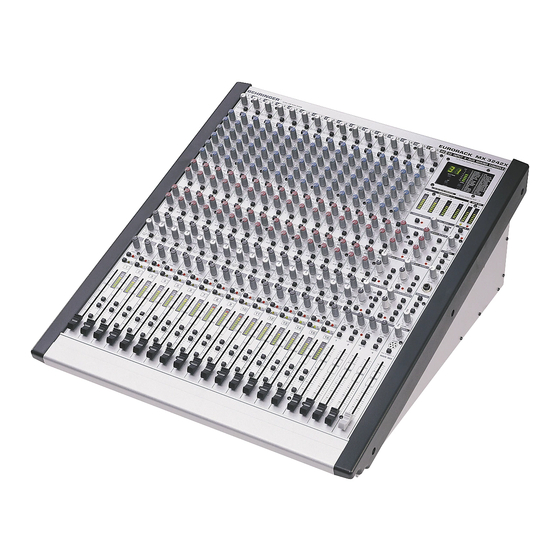
- Page 4 EURORACK ® Ultra-low noise 16/32-channel 4-bus inline mixing console with integrated VIRTUALIZER multi-effects processor.
- Page 5 TABLE OF CONTENTS 1. INTRODUCTION........................7 2. OPERATION .......................... 10 3. PRACTISE ..........................23...
-
Page 6: Table Of Contents
4. APPLICATIONS ........................24 5. TECHNICAL BACKGROUND ....................33 6. INSTALLATION ........................34 7. APPENDIX ..........................37 8. WARRANTY ........................... 39... - Page 7 1. INTRODUCTION 1.1 Concept...
-
Page 8: Before You Start
1.1.1 Architecture Main input channels Mix-B input channels Subgroups Channel outputs Aux Sends Stereo Aux Returns (additional stereo Line inputs) Main Mix output (“master”) 24-bit digital Effects Processor 1.2 Before you start 1.2.1 Level meters Fig. 1.1: Subgroup and Main Mix level meters... - Page 9 When you activate the MUTE switch, the level meters in the main input channels offer you two helpful functions: If a signal is present in the main input channel, the lowest green LED lights up (signal present). If the gain setting is too high, the red CLIP LED on top of the channel level meter lights up.
- Page 10 1.2.4 Shipping If the unit is damaged, please do not return it to us, but notify your dealer and the shipping company immediately. Otherwise claims for damage or replacement may not be granted. 1.2.5 Mounting the MX3242X in a rack Ensure sufficient air space around the MX3242X.
- Page 11 Fig. 2.2: Phantom power switch Mute the sound system before you turn on phantom power. Otherwise, power-up thumps could be played back by the monitor speakers. Fig. 2.3: Gain control and Lo Cut filter Please note that you can only use either of the Mic and Line inputs, but never both at the same time! 2.1.1 Input level setting Please note that too high a monitoring level can lead to hearing damage.
- Page 12 2.1.2 Equalizer Fig. 2.4: Equalizer 2.1.3 Aux Send buses Fig. 2.5: Aux Sends...
- Page 13 2.1.4 Routing, fading and muting Fig. 2.6: Fader range of Main input channel...
- Page 14 2.1.5 FLIP switch 2.2 Mix-B input channel 2.2.1 Input level setting Fig. 2.7: OPERATING LEVEL button for Mix-B input channels 2.2.2 Aux Send buses...
- Page 15 2.2.3 Routing Fig. 2.8: Controlling the Mix-B signal 2.3 Insert points and direct outputs Fig. 2.9: Wiring a Compressor to the insert path of a Main input channel...
- Page 16 2.3.1 Main input channels 2.3.2 Subgroups 2.3.3 Main mix 2.3.4 Direct output on each Main input channel Fig. 2.10: Using the direct outputs for multi-track recording post-fader...
- Page 17 2.4 Main section 2.4.1 Aux Send buses Fig. 2.11: Aux Send Main section 2.4.2 Aux Returns – additional stereo line inputs Fig. 2.12: Aux Return Main section...
- Page 18 2.4.3 Level meters 2.4.4 CHANNEL MODE and SOLO MASTER LEVEL controls Fig. 2.13: PFL/SOLO Main section SOLO 2.4.5 Mix-B Fig. 2.14: Mix-B Main Section...
- Page 19 2.4.6 Monitor section Fig. 2.15: Monitor section All buttons are effective on the monitor output only. They will not affect the Main Mix signal delivered by the Main outputs. 2.4.7 Headphones section Fig. 2.16: Headphones section Please note that too high a monitoring level can lead to hearing damage.
- Page 20 2.4.8 Subgroups and Main Mix fader Fig. 2.17: Subgroups section 2.4.9 Digital Effects Processor Fig. 2.18: Digital effects module...
- Page 21 Preset name Preset name Cathedral 1 Echo Cathedral 2 Short Gated Reverb Medium Plate Medium Gated Reverb Bright Plate Slow Chorus Small Hall Medium Chorus Medium Hall Fast Chorus Room Medium Flanger Medium Studio Bright Flanger Large Studio Delay & Reverb Medium Concert 26 Chorus &...
- Page 22 Echo: Gated Reverb: Flanger: Chorus: Pitch Shifter: Delay & Reverb: Chorus & Reverb: Flanger & Reverb: Radio Speaker: Distortion: 2.4.10 Talkback facility: communicating with performers in the studio Fig. 2.19: Talkback section...
- Page 23 3. PRACTISE 3.1 Selecting inputs 3.2 Initializing channels for gain setting 3.3 Auditioning a signal and setting up a channel 3.4 Desk normalization 3.5 Multi-track initialization 3.6 Recording levels...
-
Page 24: Applications
3.7 Track sheet 4. APPLICATIONS 4.1 Recording situation Fig. 4.1: Recording situation: example of typical connection scheme... - Page 25 In a recording situation the recorded material should always be monitored via the Tape Return bus. In a recording situation both monitor mix and effect sends should always be assigned to the Tape Return bus. 4.2 Live situation Fig. 4.2: Live situation: example of typical connection scheme...
- Page 26 4.3 Patchbay 4.3.1 Patchbay configuration 4.3.2 Parallel Fig. 4.1: Patchbay mode “parallel” 4.3.3 Half-normalled Fig. 4.2: Patchbay mode “half-normalled”...
- Page 27 4.3.4 Normalled Fig. 4.3: Patchbay mode “normalled” 4.3.5 Open Fig. 4.4: Patchbay mode “open” 4.3.6 Patchbay organization...
- Page 28 Fig. 4.1: Example of a studio organization with four Patchbays...
- Page 29 4.3.7 Looming problems 4.4 Expanding the MX3242X 4.4.1 Expander Port Fig. 4.8: Expander Port connectors Fig. 4.9: Connecting several consoles via their Expander Ports...
- Page 30 PIN-NO. DOCK INPUT DOCK OUTPUT AUX SEND 1 AUX SEND 1 AUX SEND 3 AUX SEND 3 AUX SEND 5 AUX SEND 5 SUBGROUP 1 SUBGROUP 1 SUBGROUP 3 SUBGROUP 3 MIX-B L MIX-B L MAIN MIX L MAIN MIX L AUX SEND 2 AUX SEND 2 AUX SEND 4...
- Page 31 Fig. 4.10: Partial view of pc board carrying 8 mono and 8 Mix-B input channels...
- Page 32 Here’s how to do it: Fig. 4.11: Cut pcb track and solder jumper J1 through J8: changing Aux Send 1/2 from POST MUTE to POST EQ. J9 through J16: changing direct out signal from Main input channel to Mix-B. J17 through J24: changing Direct Out from POST FADER to PRE MUTE (makes sense only if J9 through J16 are left unmodified).
-
Page 33: Technical Background
J33 through J40: changing Meters from POST FADER to PRE FADER. 5. TECHNICAL BACKGROUND 5.1 Mixing 5.1.1 Equalization Use the Lo Cut to tighten up channels in a mix: maybe remove it only for the bass, kick drum, toms, tablas, didgeridoo and other deliberate subsonics (when recording classical music ignore this advice). -
Page 34: Installation
5.1.2 Gain optimization 6. INSTALLATION If the unit is damaged, please do not return it to us, but notify your dealer and the shipping company immediately, otherwise claims for damage or replacement may not be granted. Ship- ping claims must be made by the consignee. 6.1 Rack mounting Ensure sufficient air space around the MX3242X. -
Page 35: Mains Connection
Please note that both PSU and EURORACK will heat up during operation. This is completely normal and does not indicate a malfunction. 6.2 Mains connection Please make sure that all units have a proper ground connection. For your own safety, it is advisable not to remove the ground connection within the units or at the supply, or fail to make this connection at all. - Page 36 Unbalanced use of Balanced use of mono 1/4" jack plugs stereo 1/4" jack plugs Tip = Tip = Signal hot (+ve) Ring = cold (-ve) Sleeve = Ground / Shield Sleeve = Ground / Shield Ring Sleeve Sleeve Strain relief clamp Strain relief clamp For connection of balanced and unbalanced plugs, ring and sleeve have...
-
Page 37: Appendix
7. APPENDIX 7.1 Specifications Mono input channels Main Mix Digital Effects Processor Power Supply Dimensions/weight... - Page 38 7.2 Track sheet Fig. 7.2: Track sheet...
-
Page 39: Warranty
8. WARRANTY § 1 WARRANTY CARD/ONLINE REGISTRATION § 2 WARRANTY § 3 RETURN AUTHORIZATION NUMBER BEFORE § 5 WARRANTY TRANSFERABILITY § 4 WARRANTY REGULATIONS § 6 CLAIM FOR DAMAGES § 7 OTHER WARRANTY RIGHTS AND NATIONAL LAW...