Table of Contents
Advertisement
Quick Links
Advertisement
Table of Contents

Related Manuals for Behringer EURODESK MX9000


Summary of Contents for Behringer EURODESK MX9000
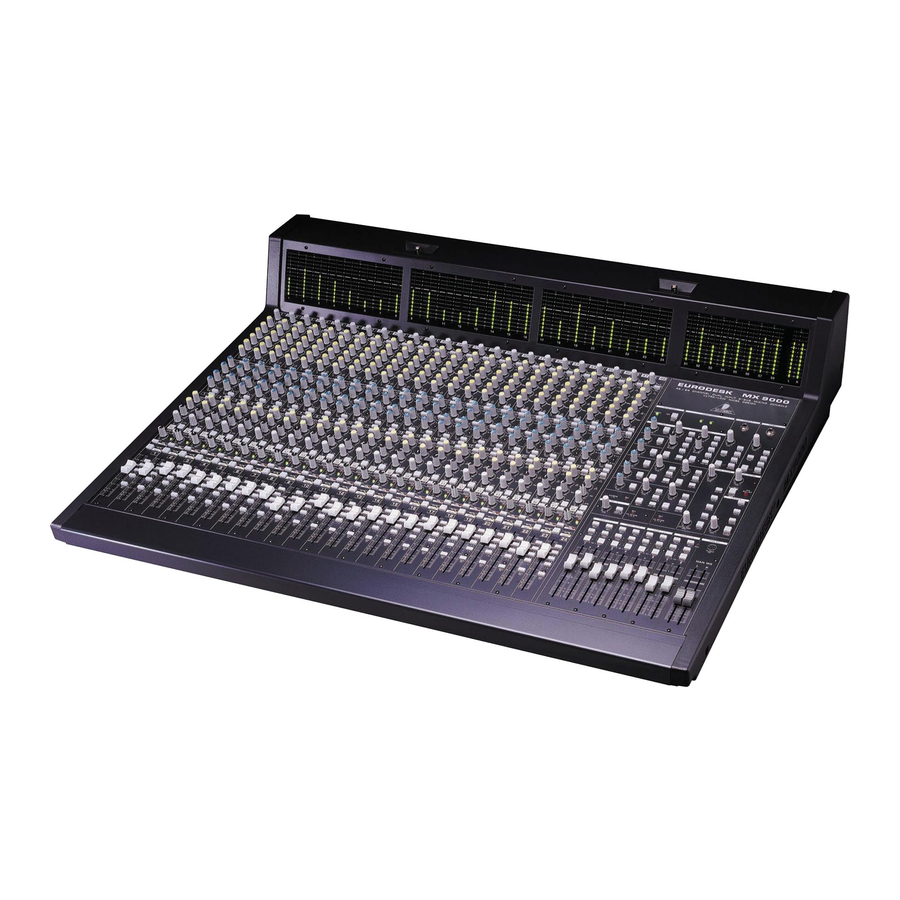
- Page 1 All manuals and user guides at all-guides.com User´s Manual...
- Page 2 All manuals and user guides at all-guides.com SAFETY INSTRUCTIONS...
- Page 3 All manuals and user guides at all-guides.com FOREWORD...
-
Page 4: Table Of Contents
All manuals and user guides at all-guides.com TABLE OF CONTENT 1. THE MANUAL .......................... 6 2. EURODESK OVERVIEW ......................6 3. INPUT/OUTPUT CHANNEL ....................8 4. INSERTS ..........................13 5. SUBGROUP AND DIRECT OUTPUTS ................14 6. MASTER PANEL ........................16 7. - Page 5 15.16-TRACK RECORDING WITH 2 SAMPLERS ..............41 16.PROFESSIONAL 24-TRACK STUDIO ................42 17.LIVE P.A. WITH 2-TRACK RECORDING ................45 18.LIVE CONCERT WITH 24-TRACK RECORDING ............... 46 19.EXPANDING THE EURODESK MX9000 ................48 20.TIMECODE ........................... 48 21.BOUNCING ........................... 49 22.SEQUENCING “LIVE” ......................49 23.INPUT/OUTPUT CONFIGURATION ...................
-
Page 6: The Manual
All manuals and user guides at all-guides.com 1. THE MANUAL 1.1 Nomenclature 1.2 An un-holstic approach 1.3 Key Prefix Meaning Switch Potentiometer Fader Tab. 1.1: Meaning of the used prefixes 2. EURODESK OVERVIEW 2.1 Architecture... - Page 7 All manuals and user guides at all-guides.com 2.2 Metering 2.3 PSU (Power Supply Unit)
-
Page 8: Input/Output Channel
All manuals and user guides at all-guides.com 3. INPUT/OUTPUT CHANNEL 3.1 Channel strip 3.2 Input switching Fig. 3.1: Input... - Page 9 All manuals and user guides at all-guides.com Fig. 3.2: Channel input switching architecture 3.3 Input gain setting...
- Page 10 All manuals and user guides at all-guides.com 3.4 Main equalizer Fig. 3.3: Main equalizer 3.5 Aux sends...
- Page 11 All manuals and user guides at all-guides.com Fig. 3.4: Aux sends 3.6 Routing and muting...
- Page 12 All manuals and user guides at all-guides.com Fig. 3.5: Routing 3.7 B-channel...
-
Page 13: Inserts
All manuals and user guides at all-guides.com Fig. 3.6: B-channel 4. INSERTS... -
Page 14: Subgroup And Direct Outputs
All manuals and user guides at all-guides.com Fig. 4.1: Post EQ channel insert 5. SUBGROUP AND DIRECT OUTPUTS 5.1 Subgroups... - Page 15 All manuals and user guides at all-guides.com Fig. 5.1: Stereo subgroup channel schematic...
-
Page 16: Master Panel
All manuals and user guides at all-guides.com Fig. 5.2: Using insert to add channel EQ to subgroup output (while keeping the number of line inputs unchanged!) 5.2 Direct outputs 6. MASTER PANEL 6.1 Aux masters... - Page 17 All manuals and user guides at all-guides.com Fig. 6.1: Aux sends...
- Page 18 All manuals and user guides at all-guides.com Fig. 6.2: Stereo aux returns...
- Page 19 All manuals and user guides at all-guides.com 6.2 MIX-B master Fig. 6.3: Mix-B...
- Page 20 All manuals and user guides at all-guides.com 6.3 Monitoring Fig. 6.4: Monitoring...
- Page 21 All manuals and user guides at all-guides.com 6.4 Headphones Fig. 6.5: Phones...
- Page 22 All manuals and user guides at all-guides.com 6.5 PFL/SOLO Fig. 6.6: Solo section 6.6 Talkback Fig. 6.7: Talkback...
-
Page 23: Connections
All manuals and user guides at all-guides.com 7. CONNECTIONS 7.1 Rear panel Fig. 7.1: Expander port bus inputs... - Page 24 All manuals and user guides at all-guides.com Fig. 7.2: Power supply unit connector Fig. 7.3: Auxiliary sends Fig. 7.4: Auxiliary returns...
- Page 25 All manuals and user guides at all-guides.com Fig. 7.5: Subgroup inserts Fig. 7.6: 2-track in/out Fig. 7.7: Additional connectors...
- Page 26 All manuals and user guides at all-guides.com Fig. 7.8: Main balanced outputs Fig. 7.9: A and B-channel input section...
- Page 27 All manuals and user guides at all-guides.com Fig. 7.10: MIX-B operating level switch and phantom power switch Fig. 7.11: Subgroup outputs/tape sends and operating level switch...
- Page 28 All manuals and user guides at all-guides.com 7.2 Plug soldering guide...
- Page 29 All manuals and user guides at all-guides.com...
-
Page 30: The Patchfield
All manuals and user guides at all-guides.com 8. THE PATCHFIELD 8.1 The normalized bay 8.2 The patchfield... - Page 31 All manuals and user guides at all-guides.com Fig. 8.1: Example of patchbay configurations...
- Page 32 All manuals and user guides at all-guides.com Fig. 8.2: Wiring for bay 8 (for advanced wiring scheme refer to section 11) 8.3 Looming problems...
-
Page 33: Equalization
All manuals and user guides at all-guides.com 9. EQUALIZATION... -
Page 34: Gain Optimization
All manuals and user guides at all-guides.com 10. GAIN OPTIMIZATION... -
Page 35: Impedances And Tuning
All manuals and user guides at all-guides.com 11. IMPEDANCES AND TUNING Fig. 11.1: Resistor-buffered parallel wiring for bay 8 (see section 8 “The patchfield”) 12. (UN)BALANCED LINES... -
Page 36: Start-Up
All manuals and user guides at all-guides.com Fig. 12.1: A balanced microphone line 13. START-UP 13.1 A-channel setting up procedure... - Page 37 All manuals and user guides at all-guides.com 13.2 Desk/tape setting up procedures...
-
Page 38: Track Midi Suite/Dance Production Studio
All manuals and user guides at all-guides.com 14. 8-TRACK MIDI SUITE/DANCE PRODUCTION STUDIO... - Page 39 All manuals and user guides at all-guides.com 14.1 Sends Fig. 14.1: Send routing 14.2 Auxless headphones mix Fig. 14.2: Simple auxless headphones mix...
- Page 40 All manuals and user guides at all-guides.com Fig. 14.3: Slightly more complicated auxless headphones mix Fig. 14.4: Subgroup-driven auxless headphones mix 14.3 Returns...
-
Page 41: Track Recording With 2 Samplers
All manuals and user guides at all-guides.com 14.4 Lining up record/sample inputs 14.5 Mixdown 15. 16-TRACK RECORDING WITH 2 SAMPLERS 15.1 Recording... -
Page 42: Professional 24-Track Studio
All manuals and user guides at all-guides.com 15.2 Headphones Fig. 15.1: Headphones 15.3 Mixdown 16. PROFESSIONAL 24-TRACK STUDIO 16.1 Recording... - Page 43 All manuals and user guides at all-guides.com Channels Source Route Destination Kick Direct out Track 2 Snare Direct out Track 3 Hi Hat Direct out Track 4 Tom 1 Subgroups 5 and 6 Tracks 5 and 6 Tom 2 Subgroups 5 and 6 Tracks 5 and 6 Tom 3 Subgroups 5 and 6...
-
Page 44: Live P.a. With 2-Track Recording
All manuals and user guides at all-guides.com 16.2 Very tricky headphones 16.3 Wet monitoring 16.4 Mixdown 17. LIVE P.A. WITH 2-TRACK RECORDING... - Page 45 All manuals and user guides at all-guides.com Channels Source Wedges / monitoring Kick Subgroups 1 and 2 / MIX-B Aux send 1 and 2 Snare Subgroups 1 and 2 / MIX-B Aux send 4 Aux send 1 and 2 Hi Hat Subgroups 1 and 2 / MIX-B Aux send 1 and 2 Tom 1...
-
Page 46: Live Concert With 24-Track Recording
All manuals and user guides at all-guides.com 18. LIVE CONCERT WITH 24-TRACK RECORDING Channels Source Tape route Destination Kick Direct out Track 1 Snare Direct out Track 2 Hi Hat Direct out Track 3 Tom 1 Subgroups 5 and 6 Tracks 5 and 6 Tom 2 Subgroups 5 and 6 Tracks 5 and 6 Tom 3... - Page 47 All manuals and user guides at all-guides.com Channels Source F.O.H. Wedges Infills Kick MIX-B Subgroups 1/2, 3/4 and 7/8 Snare MIX-B Aux send 4 Aux send 1 and 2 Subgroups 1/2 and 3/4 Hi Hat MIX-B Subgroups 1/2 and 3/4 Tom 1 MIX-B Aux send 4...
-
Page 48: Expanding The Eurodesk Mx9000
All manuals and user guides at all-guides.com 19. EXPANDING THE EURODESK MX9000 19.1 Connections 19.2 Alignment 20. TIMECODE... -
Page 49: Bouncing
All manuals and user guides at all-guides.com 21. BOUNCING 22. SEQUENCING “LIVE”... -
Page 50: Input/Output Configuration
All manuals and user guides at all-guides.com 23. INPUT/OUTPUT CONFIGURATION Nominal level Balanced Attenuation EURODESK internal +4 dBu XLR microphone input Trimpot / PAD switch Line A input +4 dBu Trimpot Line B / tape input +4 dBu / -10 dBV Gain switch Aux sends +4 dBu... - Page 51 All manuals and user guides at all-guides.com 24.1 Aux sends > post EQ Fig. 24.1: Modifications aux send > post EQ 24.2 MIX-B source > post fader Fig. 24.2: Modifications MIX-B source > post fader 24.3 LED meters > pre fader Fig.
-
Page 52: Specifications
All manuals and user guides at all-guides.com 25. SPECIFICATIONS... - Page 53 All manuals and user guides at all-guides.com BEHRINGER is constantly striving to maintain the highest professional standards. As a result of these efforts, modifications may be made from time to time to existing products without prior notice. Specifications and appearance may differ from those listed or...
-
Page 54: Warranty
(user included) will void the warranty. shall, at its sole discretion, either repair or replace the product. 6. If an inspection of the product by BEHRINGER shows that the 2. If the warranty claim proves to be justified, the product will be defect in question is not covered by the warranty, the inspection returned to the user freight prepaid. - Page 55 All manuals and user guides at all-guides.com...
- Page 56 All manuals and user guides at all-guides.com...
- Page 57 All manuals and user guides at all-guides.com...