Table of Contents
Advertisement
Advertisement
Table of Contents

Related Manuals for York ARTTP001S


Summary of Contents for York ARTTP001S
- Page 1 THERMOSTATS YORK ®...
-
Page 2: Table Of Contents
...................................... 3.1 - Thermostat ARTTP001S (SMS-1) terminals ....................3.2 - Thermostat ARTTP002S (SHP-2) terminals ....................3.3 - Connections between thermostat and equipment ARTTP001S (SMS-1) ..........3.4 - Connections between thermostat and equipment ARTTP002S (SHP-2) ..........4 - Operating the thermostat .............................. -
Page 3: Specifications
- SOH/SIH 076-240 (with or without electrical heating) - RTH 07 30 (with or without electrical heating) - SCOH/SIH 076-240 (with or without electrical heating) 1.2 - Technical data • ARTTP001S (SMS-1) Description Values This thermostat may be used with the following units:... -
Page 4: Installation And Wiring
Thermostat cover lock If desired, insert the plastic lock piece into the bottom of the mounted base. 2.6 - Dip Switch options and functions for ARTTP001S (SMS-1) The ends of the lock piece should fit P l a s t i c... -
Page 5: Dip Switch Settings For Arttp002S (Shp-2)
8 LED2 icon OFF/ON Optional selection: LCD icon comes on with LED2 (compressor fault) 3 - Wiring 3.1 - Thermostat ARTTP001S terminals 3.2 - Thermostat ARTTP002S terminals Jumper between 24V and R must be installed. Jumper between 24V and R must be installed. -
Page 6: Connections Between Thermostat And Equipment Arttp001S (Sms-1)
3 - Wiring (cont’d) 3.3 - Connections between thermostat and equipment 3.4 - Connections between thermostat and equipment terminals - A R T T P 0 0 1 S terminals - A R T T P 0 0 2 S Thermostat Unit Thermostat... -
Page 7: Operating The Thermostat
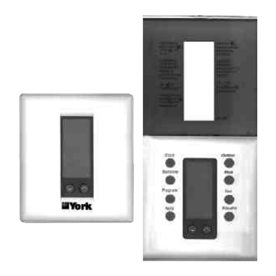
4 - Operating the thermostat Press to set the Press to display the real time Day, outdoor temperature Hour and Minute (Optional) Clock Outdoor Press to set the Heating Press to select & Cooling setpoints Heat/Cool/Auto/Off. The word is displayed for 5 Set temp Mode seconds. -
Page 8: Programming The Thermostat
5 - Programming the thermostat 5.1 UNDERSTANDING 7 DAY PROGRAMMING For example you may program the Morning event setpoint to heat to 21°C. As a result, every Morning event of the week will It is recommended that you read and understand these ins- heat to 21°C. - Page 9 5 - Programming the thermostat (cont’d) • TEMPORARY TEMPERATURE OVERRIDE You can change the scheduled program temperature at any time without affecting the Clock Outdoor program. Pressing the button temporarily changes the scheduled program set- Set temp Mode point for a 3 hour period. Pressing the Resume button cancels the override period. Program •...
- Page 10 5 - Programming the thermostat (cont’d) • SELECTING 2 OR 4 EVENTS PER DAY These 7 day programmable thermostats have been designed so that you can select either 2 events (Day or Night ) programming or 4 events (Morn , Day , Evening , or Night ) programs.
- Page 11 5 - Programming the thermostat (cont’d) • RECORD YOUR PERSONAL SCHEDULE This blank list is for your own use. Start by selecting your NOTE : It is suggested that you set your desired Morning pro - heat/cool temperature setpoints. Determine the times you want gram times about 1 hour before the time that you actually requi - the temperatures to be active.
-
Page 12: Remote Sensors
6 - Remote sensors These thermostats will accept any combination up to a quantity of 6 indoor sensor(s), duct sensor(s) and outdoor sensor(s). The sensor(s) are connected in a daisy chain to thermostat terminals RS2, RS2 and RS+V, as shown in the relevant diagrams. -
Page 13: Sensor Wiring
6 - Remote sensors (cont’d) SINGLE SENSOR ARTTP001S / ARTTP002S ALSRS001S (SL-IDS) PLEASE NOTE : Max cable length between any 2 units : 300ft. (90m) Max. number of indoor sensors in daisy chain : 6 Max. number of duct sensors in daisy chain : 1 Max. -
Page 14: Outdoor Sensor Installation
6 - Remote sensors (cont’d) INSTALLING an ALSOS001S (SL-ODT) Outdoor tempe- door temperature should be displayed with the tree and rature sensor thermometer symbol. 16 - Re-install the cover on the outdoor sensor by hooking Introduction : it on the top and snapping the bottom into place. The ALSOS001S is designed to sense outdoor air tempe- rature and send this information by digital communications Using multiple sensors :... -
Page 15: Outdoor Sensor Wiring
6 - Remote sensors (cont’d) Outdoor sensor installation wiring diagrams Outdoor sensor only ARTTP001S / ARTTP002S ALSOS001S (Mounted indoors) Outdoor probe For proper temperature sensing, mount probe in the shade. Outdoor sensor with indoor sensor(s) ARTTP001S / ARTTP002S ALSRS001S ALSOS001S... - Page 16 E - UG - R0002 YORK ® Europe YORK INTERNATIONAL Manufacturer reserves the right to change specifications without prior notice.