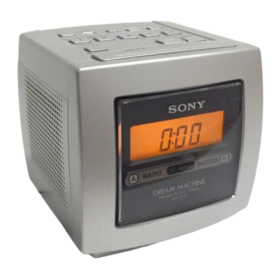
Sony ICF-C113 Service Manual
Icf-c113
fm/am pll synthesized clock radio
icf-c113l
fm/mw/lw pll synthesized clock radio
icf-c113v
tv/weater/fm/am pll
synthesized clock radio
Hide thumbs
Also See for ICF-C113:
- Operating instructions (2 pages) ,
- Operating instructions (2 pages) ,
- User manual
Table of Contents
Advertisement
ICF-C113/C113L/C113V
SERVICE MANUAL
Ver 1.1 1998.11
With SUPPLEMENT 1 (9-925-933-81)
Time display :
US, UK, Australian model
EXCEPT US, UK, Australian model
Frequency range :
US model
Band
ICF-C113V
FM
87.5 – 108 MHz
AM
530 – 1,710 kHz
TV
2 – 13CH
WEATHER
1 – 5CH
EXCEPT US model
Band
ICF-C113
FM
87.5 – 108 MHz
AM (MW) 531 – 1,602 kHz
LW
––––––––
FM
87.5 – 108 MHz
AM
530 – 1,610 kHz
MICROFILM
SPECIFICATIONS
12hour
24hour
Channel step
0.1MHz
10kHz
ICF-C113L
Channel step
87.5 – 108 MHz 0.05MHz*
531 – 1,602 kHz
9kHz
153 – 279 kHz
9kHz
––––––––
0.1MHz
––––––––
10kHz
FM/AM PLL SYNTHESIZED CLOCK RADIO
FM/MW/LW PLL SYNTHESIZED CLOCK RADIO
* The frequency display is up or down by steps of 0.1MHz.
(Example : Frequency 88.05 MHz is displayed as "88.0
MHz".)
5
Speaker
Approx. 6.6 cm (2
/
in) dia.
8
Power output
130 mW (at 10% harmonic distortion)
Power requirements
US model :120V AC, 60Hz
EXCEPT US model : 220 – 230V AC, 50Hz
Dimensions
Approx. 119 x 118 x 129.5 mm (w/h/d)
3
3
1
(4
/
x 4
/
x 5
/
in) incl. projecting parts and controls
4
4
8
Mass
Approx. 630 g (1 lb 6.2 oz)
Approx. 670 g (1 lb 7.6 oz) : ICF-C113L (UK model)
Design and specifications are subject to change without notice.
TV/WEATER/FM/AM PLL
SYNTHESIZED CLOCK RADIO
US Model
ICF-C113V
E Model
Australian Model
ICF-C113
UK Model
ICF-C113L
AEP Model
ICF-C113/C113L
ICF-C113
ICF-C113L
ICF-C113V
Advertisement
Table of Contents

Related Manuals for Sony ICF-C113


Summary of Contents for Sony ICF-C113
- Page 1 ICF-C113/C113L/C113V SERVICE MANUAL US Model ICF-C113V Ver 1.1 1998.11 E Model With SUPPLEMENT 1 (9-925-933-81) Australian Model ICF-C113 UK Model ICF-C113L AEP Model ICF-C113/C113L SPECIFICATIONS Time display : * The frequency display is up or down by steps of 0.1MHz.
-
Page 2: Table Of Contents
Leakage current can be measured by any one of three methods. 4-1. Explanation of IC Terminals ........8 1. A commercial leakage tester, such as the Simpson 229 or 4-2. Printed Wiring Boards (ICF-C113/C113V) ....9 RCA WT-540A. Follow the manufacturers’ instructions to 4-3. Schematic Diagram (ICF-C113/C113V) ....11 use these instruments. -
Page 3: General
SECTION 1 GENERAL LOCATION AND FUNCTION OF CONTROL ICF-C113/C113L ICF-C113V – 3 –... -
Page 4: Disassembly
SECTION 2 DISASSEMBLY Note : Follow the disassembly procedure in the numerical order given. 2-1. CABINET (UPPER), FRONT PANEL ASSY REMOVAL Cabinet (Upper) Button 1 Screws (+P 3x35) 2 Screw (+BTP 3x12) Front panel assy 1 Screws (+P 3x35) 2-2. KEY BOARD, MAIN BOARD, POWER TRANSFOMER REMOVAL !º... -
Page 5: Electrical Adjustment
ELECTRICAL ADJUSTMENTS • Repeat the procedures in each adjustment several times, and the AM Section frequency coverage and tracking adjustments should be finally Band button : AM (ICF-C113/C113V) done by the trimmer capacitors. : MW or LW (ICF-C113L) Volume : MAX... - Page 6 Adjust for a maximum reading on level meter. WEATHER 2CH 162.4MHz TV 13CH 215.75MHz Adjustment Location : ICF-C113/C113V L3 : AM Tracking Adjustment [MAIN BOARD] (Component side) CT3 : AM Tracking Adjustment CT5 : FM Tracking Adjustment T1 : TV IF Alignment L4 —1 : FM Tracking Adjustmen...
-
Page 7: Diagrams
4-1. EXPLANATION OF IC TERMINALS ICF-C113L IC3 µPD17071 (LCD DRIVE, SYSTEM CONTROL) L3 ± 1 : MW Tracking Adjustment Pin No. Pin name Description L3 ± 2 : LW Tracking Adjustment [MAIN BOARD] INIT OUT Initial output terminal. (Component side) COLOR1 LCD back-light drive. -
Page 12: Exploded View
SECTION 5 EXPLODED VIEW NOTE : IC BLOCK DIAGRAMS • -XX, -X mean standardized parts, so they • The mechanical parts with no reference may have some difference from the original number in the exploded views are not The components identified by mark ! IC1 TA7358 (ICF-C113V) or dotted line with mark ! are critical one. - Page 13 Ref. No. Part No. Description Remark Ref. No. Part No. Description Remark X-3374-868-1 FRONT PANEL ASSY (BLCK) ! 14 1-777-921-21 CORD, POWER (C113:EXCEPT AUS/ X-3374-869-1 FRONT PANEL ASSY (WHITE) C113L:AEP) (WHITE) X-3374-870-1 FRONT PANEL ASSY (SILVER) * 15 3-020-882-01 HOLDER (TRANSFORMER) (C113,C113L) 3-020-883-01 SHEET (LED) (BLACK) 3-020-877-01 PLATE, BACK (C113V)
-
Page 14: Electrical Parts List
ALARM SECTION 6 ELECTRICAL PARTS LIST BACK-LIGHT NOTE : • Due to standardization, replacements in the • SEMICONDUCTORS In each case, u : µ , for example : The components identified by mark ! parts list may be different from the parts uA.. - Page 15 MAIN Ref. No. Part No. Description Remark Ref. No. Part No. Description Remark MAIN BOARD 1-163-989-11 CERAMIC CHIP 0.033uF 1-164-004-11 CERAMIC CHIP 0.1uF ********** 1-163-031-11 CERAMIC CHIP 0.01uF < ANTENNA > (C113V) ANT1 1-501-907-21 ANTENNA, FM WIRE 1-163-809-11 CERAMIC CHIP 0.047uF (C113L) <...
- Page 16 MAIN Ref. No. Part No. Description Remark Ref. No. Part No. Description Remark 1-163-205-00 CERAMIC CHIP 0.001uF 8-719-911-19 DIODE 1SS119 (C113V) 8-719-052-88 DIODE 1N4002 1-163-038-11 CERAMIC CHIP 0.1uF 8-719-109-88 DIODE RD5.6ES-B1 1-125-691-11 DOUBLE LAYER 0.022F 5.5V 1-163-108-00 CERAMIC CHIP 43PF <...
- Page 17 MAIN Ref. No. Part No. Description Remark Ref. No. Part No. Description Remark 8-729-120-28 TRANSISTOR 2SC1623-L5L6 1-216-065-11 RES,CHIP 4.7K 1/10W (C113V) 8-729-120-28 TRANSISTOR 2SC1623-L5L6 (C113L) 1-216-097-11 RES,CHIP 100K 1/10W 8-729-102-07 TRANSISTOR 2SC2223-F13 (C113L) 1-216-065-11 RES,CHIP 4.7K 1/10W 8-729-904-87 TRANSISTOR 2SB1197K-R (C113V) 8-729-102-07 TRANSISTOR 2SC2223-F13 1-216-073-00 METAL CHIP 1/10W...
- Page 18 ICF-C113/C113L/C113V MAIN PRIMARY SECONDARY Ref. No. Part No. Description Remark Ref. No. Part No. Description Remark R110 1-216-073-00 METAL CHIP 1/10W ! T3 1-450-922-11 TRANSFORMER, POWER (C113V) R111 1-216-097-11 RES,CHIP 100K 1/10W R112 1-216-073-00 METAL CHIP 1/10W ! T3 1-450-923-11 TRANSFORMER, POWER (C113,C113L)
- Page 19 The ICF-C113L (7CET model) is approximately the same as the ICF-C113L (AEP model). Only difference between ICF-C113L (AEP model) and ICF-C113L (7CET model) are listed. For other information, please refer to the previously issued ICF-C113/C113L/C113V service manual (9-925-933-11). DIFFERENCE TABLE ACCESSORIES &...