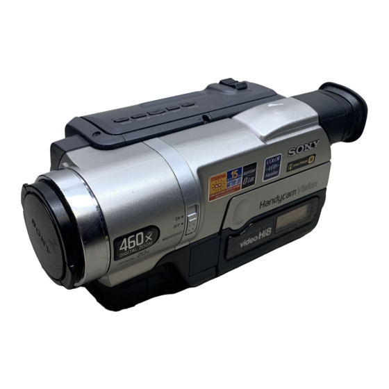
Sony Handycam Vision CCD-TRV107E Service Manual
Hi8 video camera recorder
Hide thumbs
Also See for Handycam Vision CCD-TRV107E:
- Operating instructions manual (132 pages) ,
- Operating instructions manual (204 pages) ,
- Operating instructions manual (132 pages)
Table of Contents
Advertisement
SERVICE MANUAL
Ver 1.0 2001. 12
Video camera
recorder
System
Video recording system
2 rotary heads
Helical scanning
FM system
Audio recording system
Rotary heads, FM system
Video signal
PAL colour, CCIR standards
Usable cassette
8mm video format cassette
Hi8 or standard 8
Recording/playback time
(using 90 min. Standard 8/Hi8
video cassette)
SP mode: 1.5 hours
LP mode: 3 hours
Fastforward/rewind time (using
90 min. Standard 8/Hi8 video
cassette)
Approx. 5 min.
Viewfinder
Electric Viewfinder (monochrome)
Image device
CCD-TRV408E:
4.5 mm (1/4 type) CCD
(Charge Coupled Device)
Approx. 380 000 pixels
(Effective: Approx. 230 000 pixels)
CCD-TRV107E/TRV108E/
TRV208E:
3.0 mm (1/6 type) CCD
(Charge Coupled Device)
Approx. 320 000 pixels
(Effective: Approx. 290 000 pixels)
CCD-TRV107E/TRV108E/
Photo : CCD-TRV408E
SPECIFICATIONS
Lens
Combined power zoom lens
Filter diameter 37 mm (1 7/16 in.)
CCD-TRV107E:
×
×
20
(Optical), 450
(Digital)
CCD-TRV108E:
×
×
20
(Optical), 460
(Digital)
CCD-TRV208E/TRV408E:
×
×
20
(Optical), 560
(Digital)
Focal length
3.6 - 72 mm (5/32 - 2 7/8 in.)
When converted to a 35 mm still
camera
41 - 820 mm (1 5/8 - 32 3/8 in.)
Colour temperature
Auto
Minimum illumination
CCD-TRV107E/TRV108E/TRV208E:
1 lx (lux) (F 1.4)
CCD-TRV408E:
0.3 lx (lux) (F 1.4)
0 lx (lux) (in the NightShot mode)*
* Objects unable to be seen due to
the dark can be shot with infrared
lighting.
Input/output connectors
S video output
4-pin mini DIN
Luminance signal: 1 Vp-p,
75 Ω (ohms), unbalanced
Chrominance signal: 0.3 Vp-p,
75 Ω (ohms), unbalanced
TRV208E/TRV408E
East European Model
North European Model
CCD-TRV108E/TRV208E/TRV408E
Hong Kong Model
For MECHANISM ADJUSTMENT, refer to the "8mm
Video MECHANICAL ADJUSTMENT MANUAL
M2000 MECHANISM " (9-929-861-11).
Audio/Video output
AV MINIJACK, 1 Vp-p,
75 Ω (ohms), unbalanced, sync
negative 327 mV, (at output
impedance more than 47 kΩ
(kilohms))
Output impedance with less than
2.2 kΩ (kilohms)/Monaural
minijack
(ø 3.5 mm)
RFU DC OUT
Mini-mini jack (ø 2.5 mm), DC 5V
LCD screen
Picture
6.2 cm (2.5 type)
50.3 × 37.4 mm (2 × 1 1/2 in.)
Total dot number
×
61 600 (280
220)
General
Power requirements
7.2 V (battery pack)
8.4 V (AC power adaptor)
Average power consumption
(when using the battery pack)
During camera recording using
LCD
2.6 W
Viewfinder
1.9 W
VIDEO CAMERA RECORDER
RMT-708
AEP Model
UK Model
Russian Model
E Model
Australian Model
Tourist Model
CCD-TRV107E/TRV408E
Chinese Model
CCD-TRV107E
M2100 MECHANISM
IX
Operating temperature
0 °C to 40 °C (32 °F to 104 °F)
Recommended charging
temperature
10 °C to 30 °C (50 °F to 86 °F)
Storage temperature
–20 °C to +60 °C
(–4 °F to +140 °F)
Dimensions (Approx.)
90 × 102 × 197 mm
(3 5/8 × 4 1/8 × 7 7/8 in.)
(w/h/d)
Mass (approx.)
850 g (1 lb 14 oz)
main unit only
1.0 kg (2 lb 3 oz)
including the battery pack
NP-FM30, Hi8 cassette, lens cap and
shoulder strap
Supplied accessories
See page 3.
— Continued on next page —
Advertisement
Table of Contents

Related Manuals for Sony Handycam Vision CCD-TRV107E


Summary of Contents for Sony Handycam Vision CCD-TRV107E
- Page 1 CCD-TRV107E/TRV108E/ TRV208E/TRV408E RMT-708 SERVICE MANUAL AEP Model UK Model East European Model North European Model Russian Model Ver 1.0 2001. 12 CCD-TRV108E/TRV208E/TRV408E E Model Australian Model Hong Kong Model Tourist Model CCD-TRV107E/TRV408E Chinese Model Photo : CCD-TRV408E CCD-TRV107E M2100 MECHANISM For MECHANISM ADJUSTMENT, refer to the “8mm...
- Page 2 Danger of explosion if battery is incorrectly replaced. LIST ARE CRITICAL TO SAFE OPERATION. REPLACE THESE Replace only with the same or equivalent type. COMPONENTS WITH SONY PARTS WHOSE PART NUMBERS APPEAR AS SHOWN IN THIS MANUAL OR IN SUPPLEMENTS PUBLISHED BY SONY.
- Page 3 TRV408E : AEP, UK only 4 R6 (Size AA) battery for Remote 9 2-pin conversion adaptor (1) Commander (2) CCD-TRV107E : JE/TRV408E : JE only CCD-TRV107E/TRV208E/TRV408E only 0 2-pin conversion adaptor (1) 5 A/V connecting cable (1) CCD-TRV107E : E, HK/...
-
Page 4: Table Of Contents
CCD-TRV107E/TRV108E/TRV208E/TRV408E TABLE OF CONTENTS SERVICE NOTE 2-5. CABINET (L) SECTION ················································ 2-6 2-6. CABINET (R) SECTION ··············································· 2-7 POWER SUPPLY DURING REPAIRS ····························· 7 2-7. EVF SECTION ································································ 2-7 TO TAKE OUT A CASSETTE WHEN NOT EJECT 2-8. BATTERY PANEL SECTION ········································ 2-8 (FORCE EJECT) ································································... - Page 5 CCD-TRV107E/TRV108E/TRV208E/TRV408E • VC-272 (CAMERA PROCESSOR AMP)(1/11) VCO Adjustment (PD-156 board) ································· 5-25 SCHEMATIC DIAGRAM ···························· 4-35 RGB AMP Adjustment (PD-156 board) ························ 5-25 • VC-272 (Y/C PROCESSOR)(2/11) Contrast Adjustment (PD-156 board) ···························· 5-26 SCHEMATIC DIAGRAM ···························· 4-37 COM AMP Adjustment (PD-156 board) ······················· 5-26 •...
- Page 6 CCD-TRV107E/TRV108E/TRV208E/TRV408E 6-1-8. CASSETTE COMPARTMENT ASSY, DRUM ASSY ··· 6-8 6-1-9. LS CHASSIS BLOCK ASSEMBLY ······························· 6-9 6-1-10. MECHANICAL CHASSIS BLOCK ASSEMBLY-1 ···· 6-10 6-1-11. MECHANICAL CHASSIS BLOCK ASSEMBLY-2 ···· 6-11 6-2. ELECTRICAL PARTS LIST ········································ 6-12 * Color reproduction frame is shown on page 215.
-
Page 7: Service Note
CCD-TRV107E/TRV108E/TRV208E/TRV408E SERVICE NOTE POWER SUPPLY DURING REPAIRS In this unit, about 10 seconds after power is supplied (8.4V) to the battery terminal, the power is shut off so that the unit cannot operate. The following method is available to prevent this. -
Page 8: Self-Diagnosis Function
CCD-TRV107E/TRV108E/TRV208E/TRV408E SELF-DIAGNOSIS FUNCTION Self-diagnosis Function Self-diagnosis Display When problems occur while the unit is operating, the self-diagnosis When problems occur while the unit is operating, the counter of the function starts working, and displays on the viewfinder or LCD or viewfinder or LCD or Display window shows a 4-digit display Display window what to do. -
Page 9: Self-Diagnosis Code Table
CCD-TRV107E/TRV108E/TRV208E/TRV408E Self-diagnosis Code Table Self-diagnosis Code Block Detailed Symptom/State Correction Function Code Non-standard battery is used. Use the InfoLITHIUM battery. Condensation. Remove the cassette, and insert it again after one hour. Video head is dirty. Clean with the optional cleaning cassette. - Page 10 CCD-TRV107E/TRV108E/TRV208E/TRV408E Self-diagnosis Code Block Detailed Symptom/State Correction Function Code Inspect the lens block focus reset sensor (Pin qs of CN301 of VC- Difficult to adjust focus 272 board) when focusing is performed when the control dial is (Cannot initialize focus.) rotated in the focus manual mode and the focus motor drive circuit (IC301 of VC-272 board) when the focusing is not performed.
-
Page 11: General
CCD-TRV107E/TRV108E/TRV208E/TRV408E SECTION 1 This section is extracted from GENERAL instruction manual. English Main Features Taking moving images, and playing them back •Recording a picture (p. 26) •Playing back a tape (p. 38) Others Functions to adjust exposure in the recording mode •BACK LIGHT (p. -
Page 12: Getting Started
Slide the battery pack out in the direction of the arrow while pressing V BATT down. V BATT release lever/ 1 Wireless Remote Commander (1) (p. 124) (CCD-TRV107E/TRV208E/TRV408E only) 2 AC-L10A/L10B/L10C AC power adaptor (1), Mains lead (1) (p. 16) 3 NP-FM30 battery pack (1) (p. 15, 16) 4 R6 (Size AA) battery for Remote Commander (2) (p. -
Page 13: Charging The Battery Pack
“InfoLITHIUM” battery pack. “InfoLITHIUM” M series battery packs have the mark. * Approximate continuous recording time at “InfoLITHIUM” is a trademark of Sony 25°C (77°F). The battery life will be shorter if Corporation. ° you use your camcorder in a cold environment. -
Page 14: Connecting To A Wall Socket
Using a car battery Use Sony DC Adaptor/Charger (optional). Refer to the operating instructions of the DC Adaptor/ Charger for further information. Step 2 Setting the... -
Page 15: Step 3 Inserting A Cassette
CCD-TRV107E/TRV108E/TRV208E/TRV408E Step 3 Inserting a cassette Step 3 Inserting a cassette When you want to record in the Hi8 Notes system, use Hi8 video cassettes. •Do not press the cassette compartment down. (1) Prepare the power supply (p. 15). Doing so may cause a malfunction. - Page 16 CCD-TRV107E/TRV108E/TRV208E/TRV408E Recording a picture Recording a picture During recording in the mirror mode Adjusting the LCD screen DATE and TIME on your camcorder do not work. The LCD panel moves about 90 degrees to the viewfinder side and about 180 degrees to the lens Indicators in the mirror mode side.
-
Page 17: Shooting Backlit Subjects - Back Light
CCD-TRV107E/TRV108E/TRV208E/TRV408E Recording a picture Recording a picture Indicators displayed in the Shooting backlit subjects recording mode – BACK LIGHT The indicators are not recorded on tape. When you shoot a subject with the light source behind the subject or a subject with a light background, use the backlight function. -
Page 18: Superimposing The Date And Time On Pictures
(CCD-TRV107E/TRV208E/TRV408E only) To display the screen indicators – Display function Press DISPLAY on your camcorder or the Remote Commander (CCD-TRV107E/TRV208E/ TRV408E only) supplied with your camcorder. The indicators appear on the screen. To make the indicators disappear, press DISPLAY again. -
Page 19: Viewing The Recording On Tv
Keep pressing m or M during playback. To This is not a malfunction. resume normal playback, release the button. * CCD-TRV107E/TRV208E/TRV408E only To monitor the high-speed picture while advancing or rewinding the tape (skip scan) Keep pressing m while rewinding or M while advancing the tape. -
Page 20: Advanced Recording Operations
CCD-TRV107E/TRV108E/TRV208E/TRV408E — — — Advanced Recording Operations — Using the wide mode Using the wide mode In CAMERA mode, set 16:9WIDE to CINEMA or 16:9FULL in in the menu settings (p. 79). You can record a cinema-like picture (CINEMA) or a 16:9 wide picture to watch on the 16:9 wide- screen TV (16:9FULL). -
Page 21: Using Special Effects - Picture Effect
CCD-TRV107E/TRV108E/TRV208E/TRV408E Using special effects Using the fader function – Picture effect The date, time indicator and title do not fade in or fade out You can digitally process images to obtain special Erase them before operating the fader function if effects like those in films or on the TV. -
Page 22: Adjusting The Exposure Manually
CCD-TRV107E/TRV108E/TRV208E/TRV408E Using the PROGRAM AE function Using the PROGRAM AE function (1) In CAMERA mode, select PROGRAM AE in Notes in the menu settings (p. 79). •In the spotlight, sports lesson and beach & ski • (2) Select the desired PROGRAM AE mode in the modes, you cannot take close-ups. -
Page 23: Superimposing A Title
CCD-TRV107E/TRV108E/TRV208E/TRV408E Superimposing a title Focusing manually You can select one of eight preset titles and two To focus precisely custom titles (p. 60). You can also select the Adjust the zoom by first focusing at the “T” language, colour, size, and position of titles. -
Page 24: Making Your Own Titles
CCD-TRV107E/TRV108E/TRV208E/TRV408E Making your own titles Making your own titles To change a title you have stored You can make up to two titles and store them in your camcorder. Each title can have up to 20 In step 3, select CUSTOM1 SET or CUSTOM2 characters. -
Page 25: Editing
CAUTION use the PROGRAM AE or backlight function while shooting in the AUTO mode ( •When replacing the bulb, use only the Sony •The built-in light may turn off when inserting XB-3D halogen lamp (optional) to reduce the or ejecting a cassette. -
Page 26: Dubbing A Tape Easily - Easy Dubbing
CCD-TRV107E/TRV108E/TRV208E/TRV408E Dubbing a tape easily Dubbing a tape easily – – Easy Dubbing – Easy Dubbing VCR operation for dubbing can be controlled Step 2: Setting the VCR to operate easily by using your camcorder when the VCR is with your camcorder connected. - Page 27 CCD-TRV107E/TRV108E/TRV208E/TRV408E Dubbing a tape easily Dubbing a tape easily – Easy Dubbing – Easy Dubbing When the VCR does not operate correctly (3) Setting your camcorder and the • •After checking the code in “About the IR VCR to face each other SETUP code,”...
-
Page 28: Customising Your Camcorder
20× is carried out. 40× If you set to 40×/450×, digital zoom is activated 450× and more than 20× to 40×/450× is performed digitally. (p. 30) (CCD-TRV107E only) z OFF 16:9WIDE — CAMERA CINEMA To record in the CINEMA mode. (p. 44) To record in the 16:9FULL mode. - Page 29 SEL/PUSH EXEC dial to adjust the following CAMERA •When you record in the LP mode, we recommend using a Sony video cassette so that you can get the bar. most out of your camcorder. •When you record in both the SP and LP modes on one tape, or you record some scenes in the LP mode, the playback image may be distorted.
-
Page 30: Troubleshooting
• This is not a malfunction. shoot a very bright subject. problem. If the problem persists, disconnect the power source and contact your Sony dealer or local authorised Sony service facility. If “C:ss:ss” appears on the screen, the self-diagnosis display An unknown picture is displayed on •... -
Page 31: Self-Diagnosis Display
The video heads are dirty code chart. The last two digits (indicated by ss) Slow flashing: will differ depending on the state of your – You need to clean the heads using the Sony V8-25CLD camcorder. Self-diagnosis display cleaning cassette (optional) (p. 109). -
Page 32: About The "Infolithium" Battery Pack
CCD-TRV107E/TRV108E/TRV208E/TRV408E About the “InfoLITHIUM” About video cassettes battery pack Playing back an NTSC-recorded tape You can play back tapes recorded in the NTSC What is the “InfoLITHIUM” battery video system using the SP mode. pack? However, note that the following will occur The “InfoLITHIUM”... -
Page 33: Maintenance Information And Precautions
A built-in rechargeable battery is supplied with they must be replaced with new heads. Contact your camcorder so as to retain the date and time, your Sony dealer or local authorised Sony service etc., regardless of the setting of the POWER facility. - Page 34 On handling tapes casing, unplug your camcorder and have it Do not insert anything into the small holes on the checked by a Sony dealer before operating it rear of the cassette. These holes are used to sense any further.
-
Page 35: Quick Reference
— Quick Reference — Maintenance information and Identifying the parts precautions and controls Note on dry batteries (CCD-TRV107E/ TRV208E/TRV408E only) Camcorder To avoid possible damage from battery leakage or corrosion, observe the following: – Be sure to insert the batteries with the + –... - Page 36 Sony VCRs to avoid remote control 1 Transmitter unintentional operations. If you use another Point toward the remote sensor to control Sony VCR in the commander mode VTR 2, we the camcorder after turning on the recommend changing the commander mode or camcorder.
- Page 37 CCD-TRV107E/TRV108E/TRV208E/TRV408E Identifying the parts and controls Identifying the parts and controls qa SteadyShot off indicator (CCD-TRV408E Operation indicators only) (p. 80) LCD screen and Viewfinder/ Display window/ qs Manual focusing indicator (p. 55) qd Built-in light indicator (p. 62) qf STBY/REC indicator (p. 26)/ Video control mode indicator (p.
-
Page 38: Disassembly
CCD-TRV107E/TRV108E/TRV208E/TRV408E SECTION 2 DISASSEMBLY The following flow chart shows the disassembly procedure. 2-1. Video light PD-156 board service position 2-2. LCD section (PD-156 board) VF-150, LB-073 boards service position 2-3. VF-150, LB-073 boards 2-4. Front panel section (SI-033 board) SI-033 board service position 2-5. -
Page 39: Video Light
CCD-TRV107E/TRV108E/TRV208E/TRV408E [CONNECTION OF EQUIPMENT] CPC connector CN713 Conductor side CPC lid MI screw (M2 × 4) (H) AC power AC IN Claw adaptor Info lithium battery (L series) Adjustment remote commander (RM-95) CPC-jig for SB (J-6082-539-A) NOTE: Follow the disassembly procedure in the numerical order given. -
Page 40: Lcd Section (Pd-156 Board)
CCD-TRV107E/TRV108E/TRV208E/TRV408E 2-2. LCD SECTION (PD-156 BOARD) 3 Two claws 5 Two tapping screws (B2 × 7) 4 P cabinet C 9 Two 2 Two MI screws claws (M2 × 4) (H) q; Indication LCD block assembly (20P), LCD holder qa PD-156 board,... -
Page 41: Boards
CCD-TRV107E/TRV108E/TRV208E/TRV408E 2-3. VF-150, LB-073 BOARDS 1 Raise the EVF in the A direction and slide it in the B direction. 2 Two tapping screws (B2 × 5) 7 VF lens (B) assembly 5 EVF cabinet upper 6 Two claws 8 Caution... -
Page 42: Front Panel Section (Si-033 Board)
CCD-TRV107E/TRV108E/TRV208E/TRV408E 2-4. FRONT PANEL SECTION (SI-033 BOARD) 1 Open the jack cover 3 MI screw (M2 × 4) (H) 2 Two MI screws (M2 × 4) (H) 4 Two MI screws (M2 × 4) (H) 5 Two claws Remove it while taking care as the FP-418 flexible cable is connected. -
Page 43: Cabinet (L) Section
CCD-TRV107E/TRV108E/TRV208E/TRV408E 2-5. CABINET (L) SECTION 2 Two MI screws (M2 × 4) (H) 4 Cassette lid assembly 3 Two claws 5 Two MI screws (M2 × 4) (H) 8 Cabinet (L) section 6 MI screw (M2 × 4) (H) 7 Two MI screws (M2 ×... -
Page 44: Cabinet (R) Section
CCD-TRV107E/TRV108E/TRV208E/TRV408E 2-6. CABINET (R) SECTION 1 MI screw (M2 × 4) (H) 2 MI screw (M2 × 4) (H) 6 Cabinet (R) section 4 Control switch block (CF-2000) (22P) 3 Three MI screws 5 Harness (PD-115) (M2 × 4) (H) (20P) 2-7. -
Page 45: Battery Panel Section
CCD-TRV107E/TRV108E/TRV208E/TRV408E 2-8. BATTERY PANEL SECTION 6 Screw 1 Battery terminal board (6P) 4 Control switch block (SS-2000) (5P) 3 Claw 5 Battery panel section REMOVING THE BATTERY TERMINAL BOARD AND CONTROL SWITCH BLOCK (SS-2000) 2 MI screw (M2 × 4) (H) 1 MI screw (M2 ×... -
Page 46: Board
CCD-TRV107E/TRV108E/TRV208E/TRV408E 2-10.VC-272 BOARD 7 Control switch block (FK-2000) (12P) 5 Screw (M2 × 3), lock ace, p2 4 FP-397 flexible board 8 VC-272 board 3 Two screws (M2 × 3), lock ace, p2 6 Claw 1 Two screws 2 MD frame (B) (M2 ×... -
Page 47: Mechanism Deck
CCD-TRV107E/TRV108E/TRV208E/TRV408E [SERVICE POSITION TO CHECK THE VTR SECTION] Connection to Check the VTR Section To check the VTR section, set the VTR to the “Forced VTR power ON” mode. Operate the VTR functions using the adjustment remote commander (with the HOLD switch set in the OFF position). - Page 48 CCD-TRV107E/TRV108E/TRV208E/TRV408E [SERVICE POSITION TO CHECK THE CAMERA SECTION] Connection to Check the Camera Section To check the camera section, set the camera to the “Forced camera power ON” mode. Setting the “Forced Camera Power ON” mode Exiting the “Forced Camera Power ON” mode 1) Select page: 0, address: 01, and set data: 01.
-
Page 49: Hinge Assembly
CCD-TRV107E/TRV108E/TRV208E/TRV408E 2-12.MECHANISM DECK 1 Screw 3 Control switch block (M2 × 3), (FK-2000) lock ace, p2 2 Claw 6 Mechanism deck 4 Three screws (M1.7 × 2.5) 5 MD frame (A) 2-13.HINGE ASSEMBLY (Remove the LCD unit reffering to section 2-2 before starting disassembly.) -
Page 50: Circuit Boards Location
CCD-TRV107E/TRV108E/TRV208E/TRV408E 2-14.CIRCUIT BOARDS LOCATION LB-073 (BACK LIGHT) VF-150 (RGB DRIVE/TG) CD-354 (CCD IMAGER) SI-033 PD-156 (STEADY SHOT, MIC) RGB DRIVE, TIMING GENERATOR, LCD DRIVE, BACK LIGHT DRIVE VC-272 (CAMERA, VIDEO, AUDIO, SERVO, HI/MODE CONTROL, D-D CONVERTER) 2-13... -
Page 51: Flexible Boards Location
CCD-TRV107E/TRV108E/TRV208E/TRV408E 2-15.FLEXIBLE BOARDS LOCATION The flexible boards contained in the mechanism deck are not shown. CONTROL SWITCH BLOCK CONTROL SWITCH BLOCK (SS-2000) (FK-2000) FP-400 FP-394 FP-418 CONTROL SWITCH BLOCK (PR-10000) FP-401 CONTROL SWITCH BLOCK (CF-2000) FP-397 2-14E... -
Page 52: Block Diagrams
CCD-TRV107E/TRV108E/TRV208E/TRV408E SECTION 3 BLOCK DIAGRAMS... -
Page 53: Overall Block Diagram (1/2)
CCD-TRV107E/TRV108E/TRV208E/TRV408E 3-1. OVERALL BLOCK DIAGRAM (1/2) ( ) : Page No. shown in ( ) indicates the page to refer on the schematic diagram. ZOOM IRIS CD-354 BOARD VC-272 BOARD LENS METER HALL IC2191 (4-8) M905 M906 FOCUS MOTOR ZOOM MOTOR... -
Page 54: Overall Block Diagram (2/2)
CCD-TRV107E/TRV108E/TRV208E/TRV408E 3-2. OVERALL BLOCK DIAGRAM (2/2) ( ) : Page No. shown in ( ) indicates the page to refer on the schematic diagram. FP-397 VC-272 BOARD (FLEXIBLE)(2/2) PD-156 BOARD (2/3) (PAGE 4-55) VIDEO VIDEO V LIGHT PWM LIGHT LIGHT... -
Page 55: Camera/Video Block Diagram (1/2)
CCD-TRV107E/TRV108E/TRV208E/TRV408E 3-3. CAMERA/VIDEO BLOCK DIAGRAM (1/2) ( ) : Page No. shown in ( ) indicates the page to refer on the schematic diagram. IC272 ef VC-272 BOARD PB C RF PB C RF IC2191 2 CD-354 IC272 (4-35) IC2191 7 BOARD 0.5Vp-p... -
Page 56: Camera/Video Block Diagram (2/2)
CCD-TRV107E/TRV108E/TRV208E/TRV408E 3-4. CAMERA/VIDEO BLOCK DIAGRAM (2/2) ( ) : Page No. shown in ( ) indicates the page to refer on the schematic diagram. VC-272 BOARD PB C RF IC101 wj,ef (4-42) (4-38) IC151 7 IC101 REC/PB IC151 REC/PB AMP... -
Page 57: Vtr/Camera Control Block Diagram
CCD-TRV107E/TRV108E/TRV208E/TRV408E 3-5. VTR/CAMERA CONTROL BLOCK DIAGRAM ( ) : Page No. shown in ( ) indicates the page to refer on the schematic diagram. VC-272 BOARD IC402 1 M2100 MECHA DECK REC/PB (CCD-TRV408E) (PAGE 4-30) (4-46) IC451 SI-033 BOARD (4-48) 2.3Vp-p... -
Page 58: Servo Block Diagram
CCD-TRV107E/TRV108E/TRV208E/TRV408E 3-6. SERVO BLOCK DIAGRAM ( ) : Page No. shown in ( ) indicates the page to refer on the schematic diagram. IC451 wk IC001 tk M2100 MECHA DECK VC-272 BOARD REC/PB REC/PB IC451 tj,tl,ya (PAGE 4-30) REC/PB (4-46) -
Page 59: Mode Control Block Diagram
CCD-TRV107E/TRV108E/TRV208E/TRV408E 3-7. MODE CONTROL BLOCK DIAGRAM ( ) : Page No. shown in ( ) indicates the page to refer on the schematic diagram. VC-272 BOARD CONTROL SWITCH BLOCK LI 3V BT001 (CF-2000) (PAGE 4-27) LITHIUM BATTERY IC503 (4-49) S007... -
Page 60: Audio Block Diagram
CCD-TRV107E/TRV108E/TRV208E/TRV408E 3-8. AUDIO BLOCK DIAGRAM ( ) : Page No. shown in ( ) indicates the page to refer on the schematic diagram. VC-272 BOARD (4-51) IC351 AFM PROCESS CN713 BPF MON (4-51) PB RF (FOR CHECK) IC251 MIC(L) A FADE (IC601 PB 1.5M... -
Page 61: Lcd Block Diagram
CCD-TRV107E/TRV108E/TRV208E/TRV408E 3-9. LCD BLOCK DIAGRAM ( ) : Page No. shown in ( ) indicates the page to refer on the schematic diagram. IC5501 rk PD-156 BOARD IC5501 w; PANEL ID XHD OUT IC5501 ws C SYNC CN5502 450mVp-p IC5501 rj VCC1 42 PANEL 2.8V... -
Page 62: Evf Block Diagram
CCD-TRV107E/TRV108E/TRV208E/TRV408E 3-10. EVF BLOCK DIAGRAM ( ) : Page No. shown in ( ) indicates the page to refer on the schematic diagram. IC2001 w; IC2001 rk VF-150 BOARD 0.4Vp-p 7.5Vp-p IC2001 ws VCC1 EVF 2.8V VCC2 EVF 13.3V (4-13) - Page 63 CCD-TRV107E/TRV108E/TRV208E/TRV408E 3-11.POWER BLOCK DIAGRAM (1/2) ( ) : Page No. shown in ( ) indicates the page to refer on the schematic diagram. VC-272 BOARD BATT SIG BT901 BATT/EXT SW BATTERY CN001 TERMINAL BATT UNREG BATT UNREG F001 Q003,004 CHARGE...
-
Page 64: Power Block Diagram (1/2)
CCD-TRV107E/TRV108E/TRV208E/TRV408E 3-12. POWER BLOCK DIAGRAM (2/2) ( ) : Page No. shown in ( ) indicates the page to refer on the schematic diagram. VC-272 BOARD S001 CONTROL SWITCH CN711 XCAM+STBY SW POWER BLOCK(SS-2000) XVTR MODE SW CAMERA (PAGE 4-50) -
Page 65: Printed Wiring Boards And Schematic Diagrams
CCD-TRV107E/TRV108E/TRV208E/TRV408E SECTION 4 PRINTED WIRING BOARDS AND SCHEMATIC DIAGRAMS 4-1. FRAME SCHEMATIC DIAGRAM (1/2) CD-354 BOARD CONTROL SWITCH BLOCK(FK-2000) LENS UNIT S001,002,005~009,013 IMAGER RV001 EJECT/VIDEO LIGHT/ STOP/ PAUSE/ ZOOM REW/ PLAY/RESET FP-400 FLEXIBLE TO FH(2/2) CN702 VIDEO LIGHT FP-397 VL_UNREG... -
Page 66: Frame Schematic Diagram (1/2)
CCD-TRV107E/TRV108E/TRV208E/TRV408E FRAME SCHEMATIC DIAGRAM (2/2) ND901 BACK LIGHT LCD901 2.5INCH CN5703 COM1 COM2 SEG3 SEG4 SEG5 SEG6 SEG2 LCD902 SEG7 CHARACTER DISPLAY CN5502 SEG8 CONTROL SWITCH BLOCK(CF-2000) SEG9 XVD_OUT SEG10 PD-156 BOARD SEG1 S001 (OPEN/CLOSE) PANEL_COM SEG11 1/2 TG BLOCK... -
Page 67: Printed Wiring Boards And
CCD-TRV107E/TRV108E/TRV208E/TRV408E 4-2. PRINTED WIRING BOARDS AND SCHEMATIC DIAGRAMS THIS NOTE IS COMMON FOR WIRING BOARDS AND SCHEMATIC DIAGRAMS (In addition to this, the necessary note is printed in each block) (For printed wiring boards) (Measuring conditions voltage and waveform) • b: Pattern from the side which enables seeing. -
Page 68: Ccd Imager
CCD-TRV107E/TRV108E/TRV208E/TRV408E CD-354 (CCD IMAGER) PRINTED WIRING BOARD For Schematic Diagram • : Uses unleaded solder. • Refer to page 4-58 for waveforms. CD-354 BOARD NO MARK:REC/PB MODE CCD IMAGER R :REC MODE P :PB MODE XX MARK:NO MOUNT CN2191 CAM_15V/12V... -
Page 69: Back Light(Evf)
CCD-TRV107E/TRV108E/TRV208E/TRV408E LB-073 (BACK LIGHT (EVF)) PRINTED WIRING BOARD • : Uses unleaded solder. LB-073 BOARD BACK LIGHT(EVF) XX MARK:NO MOUNT Q7701 R7701 NO MARK:REC/PB MODE UP04312008 3.3k D7702 LED DRIVE R7705 NSCW100-T38 R7704 (BACKLIGHT UNIT) 3300 IC7701 D7701 TLSU1008 BUFFER... - Page 70 CCD-TRV107E/TRV108E/TRV208E/TRV408E VF-150 (RGB DRIVE/TG) PRINTED WIRING BOARD • : Uses unleaded solder. For printed wiring board • Refer to page 4-61 for parts location. • This board consists of multiple layers. However, only the sides (layers) A and B are shown.
- Page 71 CCD-TRV107E/TRV108E/TRV208E/TRV408E For Schematic Diagram • Refer to page 4-11 for printed wiring board. • Refer to page 4-58 for waveforms. VF-150 BOARD RGB DRIVER/TG XX MARK:NO MOUNT NO MARK:REC/PB MODE FB2002 CN2001 C2011 C2013 3.3u 0.01u EVF_B R2004 EVF_R BW_Y...
- Page 72 CCD-TRV107E/TRV108E/TRV208E/TRV408E SI-033 (STEADY SHOT, MIC) PRINTED WIRING BOARD (PITCH SENSOR) For printed wiring board • Refer to page 4-61 for parts location. • This board consists of multiple layers. However, only the sides (layers) A and B are shown. • Chip parts...
-
Page 73: Steady Shot, Mic
CCD-TRV107E/TRV108E/TRV208E/TRV408E For Schematic Diagram • Refer to page 4-15 for printed wiring board. FB754 SI-033 BOARD Note:Resistor is mounted to the location CL752 where FB755 is printed STEADY SHOT, MIC XX MARK:NO MOUNT C752 NO MARK:REC/PB MODE D751 (CCD-TRV408E) MA111-(K8).S0... -
Page 74: Rgb Drive, Timing Generator, Lcd Drive, Backlight Drive) Printed Wiring Board
CCD-TRV107E/TRV108E/TRV208E/TRV408E PD-156 (RGB DRIVE, TIMING GENERATOR, LCD DRIVE, BACKLIGHT DRIVE) PRINTED WIRING BOARD • : Uses unleaded solder. For printed wiring board • Refer to page 4-61 for parts location. • This board consists of multiple layers. However, only the sides (layers) A and B are shown. - Page 75 CCD-TRV107E/TRV108E/TRV208E/TRV408E • : Uses unleaded solder. RGB DRIVE, TIMING GENERATOR, LCD DRIVE, BACKLIGHT DRIVE 4-21 PD-156...
-
Page 76: Rgb Drive, Timing Generator
CCD-TRV107E/TRV108E/TRV208E/TRV408E For Schematic Diagram • Refer to page 4-19 for printed wiring board. • Refer to page 4-59 for waveforms. PD-156 BOARD(1/2) RGB DRIVE,TIMING GENERATOR(TG BLOCK) XX MARK:NO MOUNT FB5502 NO MARK:REC/PB MODE FB5503 C5527 L5502 C5514 0.01u 22uH 6.3V... -
Page 77: Lcd Drive, Backlight Drive
CCD-TRV107E/TRV108E/TRV208E/TRV408E For Schematic Diagram • Refer to page 4-19 for printed wiring board. PD-156 BOARD(2/2) FP-394 LCD DRIVE,BACKLIGHT DRIVE(BL BLOCK) FLEXIBLE XX MARK:NO MOUNT CN5703 COM1 COM1 NO MARK:REC/PB MODE COM2 COM2 SEG3 SEG3 SEG4 SEG4 SEG5 SEG5 SEG6 R5704... - Page 78 CCD-TRV107E/TRV108E/TRV208E/TRV408E CONTROL SWITCH BLOCK(CF-2000) SWITCH XX MARK:NO MOUNT CN002 S007 REG_GND SEL/PUSH EXEC XHI_RESET SP+(BEEP) KEY_AD4 BT001 D_2.8V (LITHIUM BATTERY) LI_3V KEY_AD3 KEY_AD0 KEY_AD2 R002 REG_GND D_2.8V XHI_RESET KEY_AD1 KEY_AD4 OPEN/CLOSE SW D_2.8V REG_GND KEY_AD3 DIAL_B CH GND KEY_AD2 DIAL_A LND002 D_2.8V...
- Page 79 CCD-TRV107E/TRV108E/TRV208E/TRV408E LS-057 (S/T REEL SENSOR), FP-228 (DEW SENSOR), FP-299 (MODE SWITCH), FP-300 (TAPE TOP), FP-302 (TAPE END), FP-301 (TAPE LED) FLEXIBLE BOARDS FP-302 FP-300 FLEXIBLE (COMPONENT SIDE) LS-057 BOARD FP-300 FLEXIBLE FLEXIBLE Q002 Q001 TAPE END TAPE TOP SENSOR SENSOR...
-
Page 80: Printed Wiring Board
CCD-TRV107E/TRV108E/TRV208E/TRV408E VC-272 (CAMERA PROCESSOR AMP, Y/C PROCESSOR, FOCUS/ZOOM MOTOR DRIVE, REC/PB AMP, LINE OUT AMP, SERVO, MODE CONTROL, • : Uses unleaded solder. STEADY SHOT, HI CONTROL, AUDIO, DC-DC CONVERTER, CONNECTOR) PRINTED WIRING BOARD CAMERA, VIDEO, SERVO, MODE/HI CONTROL, AUDIO, D-D CONV. - Page 81 CCD-TRV107E/TRV108E/TRV208E/TRV408E • : Uses unleaded solder. For printed wiring board • Refer to page 4-62 for parts location. • This board consists of multiple layers. However, only the sides (layers) A and B are shown. • Chip parts Transistor Diode There are a few cases that the part printed on this diagram isn’t mounted in this model.
- Page 82 CCD-TRV107E/TRV108E/TRV208E/TRV408E For Schematic Diagram • Refer to page 4-31 for printed wiring board. • Refer to page 4-59 for waveforms. VC-272 BOARD(1/11) CAM_15V A_4.75V CAMERA PROCESSOR AMP(CH BLOCK) CAM_-7.0V XX MARK:NO MOUNT D_2.8V TO(10/11) ADCK NO MARK:REC/PB MODE R :REC MODE R279 A_2.8V...
- Page 83 CCD-TRV107E/TRV108E/TRV208E/TRV408E For Schematic Diagram • Refer to page 4-31 for printed wiring board. • Refer to page 4-59 and 4-60 for waveforms. VC-272 BOARD(2/11) R210 0 Y/C PROCESSOR (CL BLOCK) D_2.8V D_1.5V XX MARK:NO MOUNT L152 10uH L154 10uH NO MARK:REC/PB MODE A_2.8V...
-
Page 84: Focus/Zoom Motor Drive)
CCD-TRV107E/TRV108E/TRV208E/TRV408E For Schematic Diagram • Refer to page 4-31 for printed wiring board. VC-272 BOARD(3/11) FOCUS/ZOOM MOTOR DRIVE(LD BLOCK) R313 2200 XX MARK:NO MOUNT HALL_REF R314 R318 NO MARK:REC/PB MODE C309 0.22u R :REC MODE C311 R317 0.001u R306 R311... -
Page 85: Rec/Pb Amp
CCD-TRV107E/TRV108E/TRV208E/TRV408E For Schematic Diagram • Refer to page 4-31 for printed wiring board. • Refer to page 4-60 for waveforms. VC-272 BOARD(4/11) REC/PB AMP(RR BLOCK) RP_4.75V TO(10/11) REG_GND XX MARK:NO MOUNT PB_RF L101 L103 REC_L_CONT NO MARK:REC/PB MODE 220uH 22uH... -
Page 86: Line Out Amp
CCD-TRV107E/TRV108E/TRV208E/TRV408E For Schematic Diagram • Refer to page 4-31 for printed wiring board. • Refer to page 4-60 for waveforms. VC-272 BOARD(5/11) LINE OUT AMP(IO BLOCK) NO MARK:REC/PB MODE XX MARK:NO MOUNT A_4.75V C2312 L2301 TO(10/11) 10uH 6.3V REG_GND VIDEO_I/O... -
Page 87: Servo
CCD-TRV107E/TRV108E/TRV208E/TRV408E For Schematic Diagram • Refer to page 4-31 for printed wiring board. • Refer to page 4-60 for waveforms. VC-272 BOARD(6/11) DRUM_VS SERVO(SE BLOCK) NO MARK:REC/PB MODE : Cannot be measured. R :REC MODE MT_4.75V DRUM_W XX MARK:NO MOUNT... -
Page 88: Mode Control, Steady Shot
CCD-TRV107E/TRV108E/TRV208E/TRV408E For Schematic Diagram • Refer to page 4-31 for printed wiring board. • Refer to page 4-60 for waveforms. VC-272 BOARD(7/11) TO(9/11) (NOT USE) TO(1/11,8/11) TO(4/11) TO(1/11,2/11) TO(2/11) TO(1/11) TO(11/11) TO(3/11) MODE CONTROL,STEADY SHOT(VC,SE BLOCK) XX MARK:NO MOUNT NO MARK:REC/PB MODE... -
Page 89: Hi Control
CCD-TRV107E/TRV108E/TRV208E/TRV408E For Schematic Diagram • Refer to page 4-31 for printed wiring board. • Refer to page 4-60 for waveforms. LANC_IN VC-272 BOARD(8/11) LANC_OUT HI CONTROL(HI BLOCK) KEY_AD5 XX MARK:NO MOUNT KEY_AD5 XTALLY_LED MELODY_ENV XTALLY_LED NO MARK:REC/PB MODE R569 XLANC_POWER_ON... -
Page 90: Audio
CCD-TRV107E/TRV108E/TRV208E/TRV408E For Schematic Diagram • Refer to page 4-31 for printed wiring board. VC-272 BOARD(9/11) NO MARK:REC/PB MODE AUDIO(AU BLOCK) R :REC MODE P :PB MODE IC601 XX MARK:NO MOUNT VC_RF_SWP BH2222FV-E2 REC_AFM REC_AFM XVC_SCK PB_RF A_4.75V A_4.9V(VCC) PB_RF R0.5/... -
Page 91: Dc-Dc Converter
CCD-TRV107E/TRV108E/TRV208E/TRV408E For Schematic Diagram • Refer to page 4-31 for printed wiring board. • Refer to page 4-60 for waveforms. VC-272 BOARD(10/11) DC-DC CONVERTER(DD BLOCK) XX MARK:NO MOUNT NO MARK:REC/PB MODE R :REC MODE P :PB MODE Q003,004 CHARGE CONTROL... -
Page 92: Connector
CCD-TRV107E/TRV108E/TRV208E/TRV408E For Schematic Diagram • Refer to page 4-31 for printed wiring board. VC-272 BOARD(11/11) CONNECTOR(CN BLOCK) CN705 XX MARK:NO MOUNT A_4.75V A_4.75V RB707 N.C. NO MARK:REC/PB MODE A_2.8V A_2.8V EVF_VG R :REC MODE D_2.8V FP-401 D_2.8V P :PB MODE EVF_B EP_13.3V... -
Page 93: Flexible Board
CCD-TRV107E/TRV108E/TRV208E/TRV408E FP-397 FLEXIBLE BOARD FP-397 FLEXIBLE (VIDEO LIGHT) J201 S VIDEO J202 RFU DC 1-683-160- For printed wiring board There are a few cases that the part printed on this diagram isn’t mounted in this model. FP-397 FLEXIBLE 4-57... -
Page 94: Waveforms
CCD-TRV107E/TRV108E/TRV208E/TRV408E 4-3. WAVEFORMS VF-150 CD-354 BOARD BOARD CAMERA REC IC2001 w; IC2002 rk IC2191 1 3.1Vp-p 7.5Vp-p 5.3Vp-p IC2001 ws IC2191 2 7.4Vp-p 17.5Vp-p 20 msec IC2001 wf IC2191 3 7.4Vp-p 5.4Vp-p IC2001 rh IC2191 4 0.4Vp-p 17.5Vp-p 20 msec... - Page 95 CCD-TRV107E/TRV108E/TRV208E/TRV408E PD-156 VC-272 BOARD BOARD IC5501 w; IC271 5 IC5502 rk IC272 e; REC/PB 3.2Vp-p 3.8Vp-p 1.9Vp-p 3.8Vp-p 34.9nsec IC5501 ws IC271 qa IC272 ef REC/PB 0.5Vp-p 2.8Vp-p 3.8Vp-p 69.8nsec IC5501 wf IC271 waws IC272 eh 0.3Vp-p 3.8Vp-p 3.2Vp-p 105nsec...
- Page 96 CCD-TRV107E/TRV108E/TRV208E/TRV408E VC-272 BOARD IC101 4 IC503 td IC151 wf IC402 1 REC/PB REC/PB REC/PB 3.2Vp-p 2.3Vp-p 460mVp-p 30.5 µsec 50 nsec/div 0.4Vp-p 50 nsec IC151 rl IC101 qf IC402 rj IC001 tk REC/PB REC/PB 2.9Vp-p 0.4Vp-p 0.4Vp-p 0.75Vp-p 33.3 ms 50 nsec/div 2.4 µsec...
-
Page 97: Mounted Parts Location
CCD-TRV107E/TRV108E/TRV208E/TRV408E no mark : side A 4-4. MOUNTED PARTS LOCATION * mark : side B CD-354 BOARD LB-073 BOARD VF-150 BOARD SI-033 BOARD PD-156 BOARD C2191 CN7701 B-1 * C2001 * C750 C5501 L5601 * C2194 C2002 * C751 C5503... - Page 98 CCD-TRV107E/TRV108E/TRV208E/TRV408E no mark : side A * mark : side B VC-272 BOARD * C001 G-12 C128 C301 * C475 C-15 C2319 * IC601 C-12 * Q354 D-17 R158 * C002 G-12 * C129 B-14 C302 * C476 C-15 C2320...
- Page 99 CCD-TRV107E/TRV108E/TRV208E/TRV408E no mark : side A * mark : side B VC-272 BOARD R806 * R373 D-17 R811 * R379 D-17 * R816 D-10 * R382 C-16 * R817 C-11 * R387 D-16 * R818 C-11 * R388 D-16 * R819...
-
Page 100: Adjustments
CCD-TRV107E/TRV108E/TRV208E/TRV408E SECTION 5 ADJUSTMENTS... -
Page 101: Adjusting Items When Replacing Main Parts And Boards
CCD-TRV107E/TRV108E/TRV208E/TRV408E Adjusting items when replacing main parts and boards. When replacing main parts, adjust the items indicated by z in the following table. Replaced parts Block replacement Parts replacement Adjustment Adjustment Section Initialization of D, Initialization of D, E, F, 7 page data... - Page 102 CCD-TRV107E/TRV108E/TRV208E/TRV408E *1: When replacing the drum assy. or mechanism deck, reset the data of page: 2, address: A2 to Board A4 to “00”. (Refer to “Record of Use check” replacement of “5-4. SERVICE MODE”) *2: When replacing the video light, reset the data of page:2, address: E0 to E2 to “00”.
-
Page 103: Camera Section Adjustment
CCD-TRV107E/TRV108E/TRV208E/TRV408E 5-1. CAMERA SECTION ADJUSTMENT 1-1. PREPARATIONS BEFORE ADJUSTMENT (CAMERA SECTION) 1-1-1. List of Service Tools • Oscilloscope • Color monitor • Vectorscope • Regulated power supply • Digital voltmeter Ref. No. Name Parts Code Usage Auto white balance adjustment/check... -
Page 104: Preparations
CCD-TRV107E/TRV108E/TRV208E/TRV408E 1-1-2. Preparations Note1: For details of how remove the cabinet and boards, refer to “2. DISASSEMBLY”. Pattern box Note2: When performing only the adjustments, the lens block and boards need not be disassembled. Connect the equipment for adjustments according to Fig. 5-1-4. - Page 105 CCD-TRV107E/TRV108E/TRV208E/TRV408E Note: Use either a AC power adaptor or a Info-LITHIUM battery as the power supply of the CPC jig for SB. CPC jig for SB (J-6082-539-A) AC power adaptor (8.4Vdc) AC-L10 or AC-VQ800 etc LANC Terminated at 75 Ω...
-
Page 106: Precaution
CCD-TRV107E/TRV108E/TRV208E/TRV408E 1-1-3. Precaution 1. Setting the Switch Unless otherwise specified, set the switches as follows and perform adjustments without loading cassette. POWER switch (SS-2000 block) ......CAMERA DISPLAY (CF-2000 block) ..........ON NIGHT SHOT switch (Lens block) ......... OFF FOCUS switch (CF-2000 block) ......MANUAL LIGHT switch (FK-2000 block) ........ -
Page 107: Initialization Of D, E, F, 7 Page Data
CCD-TRV107E/TRV108E/TRV208E/TRV408E 1-2. INITIALIZATION OF D, E, F, 7 PAGE DATA Processing after Completing Modification of D, E, F, 7 Page data 1. Initializing the D, E, F, 7 Page Data Order Page Address Data Procedure Set the data Note1: If “Initializing the D, E, F, 7 Page Data” is performed, all... - Page 108 CCD-TRV107E/TRV108E/TRV208E/TRV408E D page 4. F Page table Address Remark Note1: Fixed data-1: Initialized data. (Refer to “1. Initializing the D, E, F, Initial data 7 Page Data”.) 51 to 52 Fixed data-1 Fixed data-2: Modified data. (Refer to “2. Modification of D, E, F, 7 Page Data”.)
- Page 109 CCD-TRV107E/TRV108E/TRV208E/TRV408E F page Address Remark Address Remark Initial data Initial data Flange back adj. EF to F1 Fixed data-1 Fixed data-2 Fixed data-2 F4 to FF Fixed data-1 Flange back adj. Table. 5-1-3. CAP FG offset adj. Switching position adj.
-
Page 110: E Page Table
CCD-TRV107E/TRV108E/TRV208E/TRV408E 5. E Page Table 6. 7 Page Table Note: Fixed data-1: Initialized data. (Refer to “1. Initializing the D, E, F, 7 Note: Fixed data-1: Initialized data. (Refer to “1. Initializing the D, E, F, 7 Page Data”.) Page Data”.) Fixed data-2: Modified data. -
Page 111: Camera System Adjustments
CCD-TRV107E/TRV108E/TRV208E/TRV408E 1-3. CAMERA SYSTEM ADJUSTMENTS Before perform the camera system adjustments, check that the specified values of “VIDEO SYSTEM ADJUSTMENTS” are satisfied. RadarW RadarW RadarW 1. HALL Adjustment For detecting the position of the lens iris, adjust AMP gain and offset. -
Page 112: Flange Back Adjustment (Using Minipattern Box)
Note3: Make the lens horizontal and perform this adjustment. at step 2 and press PAUSE button. Note4: 1/4 CCD model: CCD-TRV408E 1/6 CCD model: CCD-TRV107E/TRV108E/TRV208E Note5: The adjustment data will be automatically input to page: F, address: 46 to 55, 58. -
Page 113: Flange Back Adjustment (1)
Note3: 1/4 CCD model: CCD-TRV408E 1) Set the zoom lens to the TELE end and expose a subject that is 1/6 CCD model: CCD-TRV107E/TRV108E/TRV208E more than 500m away (subject with clear contrast such as building, etc.). (Nearby subjects less than 500m away should Switch setting: not be in the screen.) -
Page 114: Flange Back Check
CCD-TRV107E/TRV108E/TRV208E/TRV408E 4. Flange Back Check 5. Picture Frame Setting Subject Siemens star Subject Color bar chart (2.0m from the front of the lens) (Color reproduction adjustment frame) (Luminance : approx. 200 lux) (1.5m from the front of the lens) Measurement Point... -
Page 115: Color Reproduction Adjustment
CCD-TRV107E/TRV108E/TRV208E/TRV408E 6. Color Reproduction Adjustment Adjust the color Separation matrix coefficient so that proper color reproduction is produced. Subject Color bar chart (Color reproduction adjustment frame) Measurement Point Video output terminal Burst position Measuring Instrument Vectorscope Adjustment Page Adjustment Address... -
Page 116: Auto White Balance & Lv Standard Data Input
CCD-TRV107E/TRV108E/TRV208E/TRV408E RadarW RadarW RadarW 7. Auto White Balance & LV Standard Data Input Adjust the white balance reference at 3200K, and adjust the normal coefficient of the light value. Subject Clear chart (Color reproduction adjustment frame) Adjustment Page Adjustment Address 34 to 39 Note1: This adjustment should be carried out upon completion of “Color... -
Page 117: Auto White Balance Adjustment
B ratio: 5E00 to 5F00 5E: 1/4 CCD model Write down the data. Note1: 1/6 CCD model: CCD-TRV107E/TRV108E/TRV208E 1/4 CCD model: CCD-TRV408E Set the data, and press PAUSE Note2: After the power is turned on, this adjustment can be done only button. -
Page 118: White Balance Check
CCD-TRV107E/TRV108E/TRV208E/TRV408E RadarW RadarW RadarW RadarW RadarW 9. White Balance Check Subject Clear chart (Color reproduction adjustment frame) Filter Filter C14 for color temperature correction ND filter 1.0 and 0.4 and 0.1 Measurement Point Video output terminal Measuring Instrument Vectorscope Specified Value Fig. -
Page 119: Steady Shot Check (Ccd-Trv408E)
CCD-TRV107E/TRV108E/TRV208E/TRV408E RadarW RadarW RadarW RadarW RadarW 10. Steady Shot Check (CCD-TRV408E) Precautions on the Parts Replacement There are two types of repair parts. Type A: ENC03JA Type B: ENC03JB Replace the broken sensor with a same type sensor. If replace with other type parts, the image will vibrate up and down or left and right during hand-shake correction operations. -
Page 120: Electronic Viewfinder System
CCD-TRV107E/TRV108E/TRV208E/TRV408E 1-4. ELECTRONIC VIEWFINDER SYSTEM ADJUSTMENT Note : When replacing the LCD unit, be careful to prevent damages caused by static electricity. [Adjusting connector] Most of the measuring points for adjusting the viewfinder system are concentrated in CN713 of VC-272 board. -
Page 121: Rgb Amp Adjustment (Vf-150 Board)
CCD-TRV107E/TRV108E/TRV208E/TRV408E 1. RGB AMP Adjustment (VF-150 board) 1-2. Manual Adjustment Set the D range of the RGB driver used to drive the LCD to the specified value. If deviated, the LCD screen will become blackish Mode Camera or saturated (whitish). -
Page 122: Contrast Adjustment (Vf-150 Board)
CCD-TRV107E/TRV108E/TRV208E/TRV408E 2. Contrast Adjustment (VF-150 board) 2-2. Manual Adjustment Set the level of the VIDEO signal for driving the LCD to the specified value. If deviated, the screen image will be blackish or saturated Mode Camera (whitish). Subject Arbitrary Measurement Point EVF VG Note: Do either of the automatic adjustment or the manual adjustment. -
Page 123: Lcd System Adjustment
CCD-TRV107E/TRV108E/TRV208E/TRV408E 1-5. LCD SYSTEM ADJUSTMENT 1. VCO Adjustment (PD-156 board) Set the VCO free-run frequency. If deviated, the LCD screen will be blurred. Note 1: The back light (fluorescent tube) is driven by a high voltage AC power supply. Therefore, do not touch the back light holder to... -
Page 124: Rgb Amp Adjustment (Pd-156 Board)
CCD-TRV107E/TRV108E/TRV208E/TRV408E 2. RGB AMP Adjustment (PD-156 board) 3. Contrast Adjustment (PD-156 board) Set the D range of the RGB decoder used to drive the LCD to the Set the level of the VIDEO signal for driving the LCD to the specified specified value. -
Page 125: Com Amp Adjustment (Pd-156 Board)
CCD-TRV107E/TRV108E/TRV208E/TRV408E 4. COM AMP Adjustment (PD-156 board) 5. V-COM Adjustment (PD-156 board) Set the common electrode drive signal level of LCD to the specified Set the DC bias of the common electrode drive signal of LCD to the value. specified value. -
Page 126: White Balance Adjustment (Pd-156 Board)
CCD-TRV107E/TRV108E/TRV208E/TRV408E 6. White Balance Adjustment (PD-156 board) Correct the white balance. If deviated, the reproduction of the LCD screen may degenerate. Mode VTR stop Signal No signal Measurement Point Check on LCD screen Measuring Instrument Adjustment Page Adjustment Address 49, 4A Specified Value The LCD screen should not be colored. -
Page 127: Mechanism Section Adjustment
CCD-TRV107E/TRV108E/TRV208E/TRV408E 2-3. TAPE PATH ADJUSTMENT 5-2. MECHANISM SECTION ADJUSTMENT 1. Preparations for Adjustment Mechanism Section adjustments, checks, and replacement of 1) Clean the tape path face (tape guide, capstan shaft, pinch roller). mechanism parts, refer to the separate volume “8mm Video 2) Connect the adjustment remote commander. -
Page 128: Video Section Adjustments
CCD-TRV107E/TRV108E/TRV208E/TRV408E 5-3. VIDEO SECTION ADJUSTMENTS 3-1. PREPARATIONS BEFORE ADJUSTMENTS Use the following measuring instruments for video section adjustments. 3-1-1. Equipment to Required TV monitor Oscilloscope (dual-phenomenon, band width above 30 MHz with delay mode) (Unless specified otherwise, use a 10 : 1 probe.) -
Page 129: Precautions On Adjusting
CCD-TRV107E/TRV108E/TRV208E/TRV408E 3-1-2. Precautions on Adjusting Note1: Setting the “Forced VTR Power ON” mode (VTR mode) 1) Connect the adjustment remote commander to CN713 of VC- 1) Select page: 0, address: 01, and set data: 01. 272 board via CPC jig for SB (J-6082-539-A). To operate the... -
Page 130: Adjusting Connectors
CCD-TRV107E/TRV108E/TRV208E/TRV408E 3-1-3. Adjusting Connectors Some of the adjusting points of the video section are concentrated in CN713 of VC-272 board. Connect the Measuring instrument and the adjustment remote commander via the CPC jig for SB (J-6082- 539-A) to CN713. To operate the adjustment remote commander,... -
Page 131: Alignment Tape
CCD-TRV107E/TRV108E/TRV208E/TRV408E 3-1-5. Alignment Tape The following table lists alignment tapes which are available. Use the tape specified in the signal column for each adjustment. If the type of tape to be used for checking operations is not specified, use whichever type. -
Page 132: System Control System Adjustment
CCD-TRV107E/TRV108E/TRV208E/TRV408E 3-2. SYSTEM CONTROL SYSTEM ADJUSTMENT 2. Switching Position Adjustment (VC-272 board) 1. Initialization of D, E, F, 7 Page Data If deviated in this case causes switching noise or jitter on the played If the D, E, F, 7 page data is erased due to some reason, perform “1- back screen. -
Page 133: Video System Adjustments
CCD-TRV107E/TRV108E/TRV208E/TRV408E RadarW RadarW RadarW 3-4. VIDEO SYSTEM ADJUSTMENTS 2. AFC f Adjustment (VC-272 board) Adjust the pull-in range of the A/D converted clock generator during playback. Video system adjustments must be performed in the following order. Mode VTR stop [Adjusting Order]... -
Page 134: Y Out Level Adjustment (Vc-272 Board)
CCD-TRV107E/TRV108E/TRV208E/TRV408E 3. Y OUT Level Adjustment (VC-272 board) 4. C OUT Level Adjustment (VC-272 board) Set the Y signal output level. (Adjust the D/A converter out put Set the chroma signal output level. (Adjust the D/A converter out level of IC151.) put level of IC151.) -
Page 135: Rec Y Current Adjustment (Vc-272 Board)
CCD-TRV107E/TRV108E/TRV208E/TRV408E 5. REC Y Current Adjustment (VC-272 board) Adjusting method: Adjust the Y FM signal recording current. Order Page Address Data Procedure Mode VTR recording (SP mode) Set to the stop mode. Signal No signal Set the data. Measurement Point REC RF (Pin 7 of CN713) Write down the data. -
Page 136: Rec C/Afm Current Adjustment
CCD-TRV107E/TRV108E/TRV208E/TRV408E 6. REC C/AFM Current Adjustment 6-2. REC C Current Check (VC-272 board) Check the recording current level of the REC Chroma signal. If it is 6-1. Preparations too low, chroma signal noise in played back picture will be increased. -
Page 137: Rec Afm Current Adjustment (Vc-272 Board)
CCD-TRV107E/TRV108E/TRV208E/TRV408E 6-3. REC AFM Current Adjustment (VC-272 board) 6-4. Processing after completed adjustment Set the recording levels of the REC AFM signal. If the level is too low, the audio S/N will be deteriorated. If too high, color beets will... -
Page 138: Audio System Adjustments
CCD-TRV107E/TRV108E/TRV208E/TRV408E 3-5. AUDIO SYSTEM ADJUSTMENTS 1. 1.5 MHz Deviation Adjustment (VC-272 board) Adjust to the optimum 1.5MHz audio FM signal deviation. If the adjustment is not correct, its playback level will differ from [Connecting the measuring instruments for the audio] that of other units. -
Page 139: Service Mode
CCD-TRV107E/TRV108E/TRV208E/TRV408E 5-4. SERVICE MODE 4-1. ADJUSTMENT REMOTE COMMANDER 2. Precautions Upon Using the Adjustment Remote Commander The adjustment remote commander is used for changing the Mishandling of the adjustment remote commander may erase the calculation coefficient in signal processing, EVR data, etc. The adjustment remote commander performs bi-directional correct adjustment data at times. -
Page 140: Data Process
CCD-TRV107E/TRV108E/TRV208E/TRV408E 4-2. DATA PROCESS The calculation of the DDS display and the adjustment remote commander display data (hexadecimal notation) are required for obtaining the adjustment data of some adjustment items. In this case, after converting the hexadecimal notation to decimal notation, calculate and convert the result to hexadecimal notation, and use it as the adjustment data. -
Page 141: Service Mode
CCD-TRV107E/TRV108E/TRV208E/TRV408E 4-3. SERVICE MODE Note: After the completion of the all adjustments, cancel the service mode by either of the following ways. 1) Unplug the main power supply and remove the lithium battery. (In this case, date and time and menu setting have been set by users are canceled. -
Page 142: Emergency Memory Address
CCD-TRV107E/TRV108E/TRV208E/TRV408E 2. Emergency Memory Address 2-1. EMG code (Emergency code) The codes shown in the following table which correspond to errors that occur are recorded in addresses 10, 14, and 18. Page F Address 10 to 1B Code Type of Emergency... -
Page 143: Msw Codes
CCD-TRV107E/TRV108E/TRV208E/TRV408E 2-2. MSW codes • The lower parts of the data of addresses 12, 16 and 1A represent the MSW codes (mode switch, mechanism position) when errors occurs. • The upper parts of the data of addresses 12, 16 and 1A represent, when the mechanism position is to be moved, the MSW codes at the start of movement (when moving the loading motor). -
Page 144: Bit Value Discrimination
CCD-TRV107E/TRV108E/TRV208E/TRV408E 3. Bit Value Discrimination Bit values must be discriminated using the display data of the Display on the Bit values adjustment remote commander for the following items. Us the table adjustment bit3 bit2 bit1 bit0 below to discriminate if the bit value is “1” or “0”. -
Page 145: Switch Check (3)
CCD-TRV107E/TRV108E/TRV208E/TRV408E 6. Switch check (3) Page 2 Address 60 to 65 Using method: 1) Select page: 2, address: 60 to 65. 2) By discriminating the display data, the pressed key can be discriminated. Data Address 00 to 0C 0D to 24... -
Page 146: Record Of Self-Diagnosis Check
CCD-TRV107E/TRV108E/TRV208E/TRV408E 8. Record of Self-diagnosis check Page 2 Address B0 to C6 Address Self-diagnosis code “Repaired by” code (Occurred 1st time) *1 “Block function” code (Occurred 1st time) “Detailed” code (Occurred 1st time) “Repaired by” code (Occurred 2nd time) *1 “Block function”... -
Page 147: Repair Parts List
CCD-TRV107E/TRV108E/TRV208E/TRV408E SECTION 6 REPAIR PARTS LIST 6-1. EXPLODED VIEWS NOTE: • -XX, -X mean standardized parts, so they may • Abbreviation The components identified by mark 0 or have some differences from the original one. AUS : Australian model dotted line with mark 0 are critical for safety. -
Page 148: F Panel Section
CCD-TRV107E/TRV108E/TRV208E/TRV408E 6-1-2. F PANEL SECTION SE751 LAMP, HALOGEN XB-3D (HL6V/3W) SE750 D750 D752 supplied IC750 MIC901 supplied Ref. No. Part No. Description Remarks Ref. No. Part No. Description Remarks X-3952-081-1 PANEL (20) ASSY, F 3-072-179-01 RETAINER(FRONT)(20),MICROPHONE (TRV107E/TRV208E/TRV408E) D750 8-719-060-65 DIODE DAC3825... -
Page 149: Cabinet (L) Section
CCD-TRV107E/TRV108E/TRV208E/TRV408E 6-1-3. CABINET (L) SECTION Battery panel section (See page 6-4) Mechanism deck (See page 6-8 to 6-11) supplied EVF section (See page 6-5) Lens section (See page 6-6) Ref. No. Part No. Description Remarks Ref. No. Part No. Description... -
Page 150: Battery Panel Section
CCD-TRV107E/TRV108E/TRV208E/TRV408E 6-1-4. BATTERY PANEL SECTION not supplied BT901 Ref. No. Part No. Description Remarks Ref. No. Part No. Description Remarks X-3952-099-1 PANEL (20) ASSY, BATTERY 3-072-203-01 KNOB (20), BATTERY RELEASE 3-067-347-01 MI SCREW M2 (H) 3-968-771-01 SPRING, COMPRESSION 3-072-200-01 BLIND (20), BATTERY... -
Page 151: Evf Section
CCD-TRV107E/TRV108E/TRV208E/TRV408E 6-1-5. EVF SECTION LCD903 Ref. No. Part No. Description Remarks Ref. No. Part No. Description Remarks 3-072-196-01 BASE (20), VF A-7078-025-A VF-150 (BW) BOARD, COMPLETE 3-941-343-21 TAPE (A) A-7078-026-A LB-073 (BW) BOARD, COMPLETE 3-072-185-01 PLATE (20), FIXED, SLIDE 3-072-214-01 GUIDE (20), LAMP... -
Page 152: Lens Section
CCD-TRV107E/TRV108E/TRV208E/TRV408E 6-1-6. LENS SECTION M906 IC2191 not supplied M905 Be sure to read “Precautions upon replacing CCD imager” on page 4-8 when changing the CCD imager. Ref. No. Part No. Description Remarks Ref. No. Part No. Description Remarks 8-848-755-01 DEVICE, LENS LSV-631B 3-968-054-11 RUBBER (FM), SHIELD 3-713-791-41 SCREW (M1.7X5), TAPPING, P2... -
Page 153: Cabinet (R) Section
CCD-TRV107E/TRV108E/TRV208E/TRV408E 6-1-7. CABINET (R) SECTION LCD901 ND901 LCD902 supplied supplied : The printed wiring board of the Control switch block (CF-2000) on which BT001 (lithium battery) is mounted, is not shown.] CAUTION : Danger of explosion if battery is incorrectly replaced. -
Page 154: Cassette Compartment Assy, Drum Assy
CCD-TRV107E/TRV108E/TRV208E/TRV408E 6-1-8. CASSETTE COMPARTMENT ASSY, DRUM ASSY LS chassis block assembly M901 (See page 6-9) Mechanical chassis block assembly (See page 6-10 to 6-11) Ref. No. Part No. Description Remarks Ref. No. Part No. Description Remarks 3-065-932-01 PAN (2 MAIN M1.4X1.6), CAMERA 3-065-935-01 HLC CUT 1.8X4X0.5... -
Page 155: Ls Chassis Block Assembly
CCD-TRV107E/TRV108E/TRV208E/TRV408E 6-1-9. LS CHASSIS BLOCK ASSEMBLY S001 S002 not supplied Q001 H001 D001 LS-057 H002 not supplied Q002 FP-301 not supplied FP-302 not supplied FP-300 not supplied supplied Ref. No. Part No. Description Remarks Ref. No. Part No. Description Remarks... -
Page 156: Mechanical Chassis Block Assembly-1
CCD-TRV107E/TRV108E/TRV208E/TRV408E 6-1-10. MECHANICAL CHASSIS BLOCK ASSEMBLY-1 supplied M902 M903 Mechanical chassis block assembly-2 (See page 6-11) Ref. No. Part No. Description Remarks Ref. No. Part No. Description Remarks A-7096-422-A BASE ASSY, DRUM 3-065-881-01 SPRING, P PRESSURE PLATE 3-947-503-01 SCREW (M1.4) 3-065-934-01 HLW CUT 0.98X3X0.25... -
Page 157: Mechanical Chassis Block Assembly-2
CCD-TRV107E/TRV108E/TRV208E/TRV408E 6-1-11. MECHANICAL CHASSIS BLOCK ASSEMBLY-2 Ref. No. Part No. Description Remarks Ref. No. Part No. Description Remarks 3-065-920-01 ARM, HC DRIVE 7-624-101-04 STOP RING 1.2 (E TYPE) 3-065-913-01 GEAR (4), LD A-7096-412-A GEAR (T) ASSY, GUIDE 3-065-914-01 SHEET, COVER... -
Page 158: Electrical Parts List
CCD-TRV107E/TRV108E/TRV208E/TRV408E CD-354 LB-073 PD-156 6-2. ELECTRICAL PARTS LIST NOTE: • Due to standardization, replacements in the • RESISTORS When indicating parts by reference number, parts list may be different from the parts All resistors are in ohms. please include the board name. - Page 159 CCD-TRV107E/TRV108E/TRV208E/TRV408E PD-156 SI-033 Ref. No. Part No. Description Remarks Ref. No. Part No. Description Remarks C5528 1-135-177-21 TANTALUM CHIP 1uF R5508 1-218-975-11 RES-CHIP 1/16W C5530 1-164-943-11 CERAMIC CHIP 0.01uF R5509 1-218-969-11 RES-CHIP 1/16W C5531 1-164-943-11 CERAMIC CHIP 0.01uF R5510 1-218-975-11 RES-CHIP...
- Page 160 CCD-TRV107E/TRV108E/TRV208E/TRV408E SI-033 VC-272 Ref. No. Part No. Description Remarks Ref. No. Part No. Description Remarks < IC > C038 1-127-688-21 TANTAL. CHIP 10uF 6.3V C038 1-135-259-11 TANTAL. CHIP 10uF 6.3V IC750 6-701-681-01 IC RPM7140-V4 C039 1-125-838-11 CERAMIC CHIP 2.2uF 6.3V...
- Page 161 CCD-TRV107E/TRV108E/TRV208E/TRV408E VC-272 Ref. No. Part No. Description Remarks Ref. No. Part No. Description Remarks C163 1-125-777-11 CERAMIC CHIP 0.1uF C305 1-125-777-11 CERAMIC CHIP 0.1uF C164 1-125-777-11 CERAMIC CHIP 0.1uF C306 1-125-777-11 CERAMIC CHIP 0.1uF C165 1-125-777-11 CERAMIC CHIP 0.1uF C307...
- Page 162 CCD-TRV107E/TRV108E/TRV208E/TRV408E VC-272 Ref. No. Part No. Description Remarks Ref. No. Part No. Description Remarks C452 1-125-777-11 CERAMIC CHIP 0.1uF C901 1-125-777-11 CERAMIC CHIP 0.1uF C453 1-125-777-11 CERAMIC CHIP 0.1uF (TRV408E) C454 1-125-777-11 CERAMIC CHIP 0.1uF C902 1-125-777-11 CERAMIC CHIP 0.1uF...
- Page 163 CCD-TRV107E/TRV108E/TRV208E/TRV408E VC-272 Ref. No. Part No. Description Remarks Ref. No. Part No. Description Remarks < DIODE > < COIL > D001 8-719-081-19 DIODE 1SS383(T5RSONY1) L001 1-419-354-21 INDUCTOR 22uH D002 8-719-062-16 DIODE 01ZA8.2(TPL3) L002 1-416-670-11 INDUCTOR 33uH D002 8-719-075-15 DIODE MAZT082H08S0...
- Page 164 CCD-TRV107E/TRV108E/TRV208E/TRV408E VC-272 Ref. No. Part No. Description Remarks Ref. No. Part No. Description Remarks Q019 8-729-053-54 TRANSISTOR HN1A01FE-Y/GR(TPLR3) R031 1-218-973-11 RES-CHIP 1/16W Q020 8-729-053-52 TRANSISTOR HN1C01FE-Y/GR(TPLR3) R032 1-218-969-11 RES-CHIP 1/16W Q021 8-729-037-52 TRANSISTOR 2SC4738F-Y/GR(TPL3) R033 1-218-969-11 RES-CHIP 1/16W Q022 8-729-037-52 TRANSISTOR...
- Page 165 CCD-TRV107E/TRV108E/TRV208E/TRV408E VC-272 Ref. No. Part No. Description Remarks Ref. No. Part No. Description Remarks R169 1-218-953-11 RES-CHIP 1/16W R322 1-218-965-11 RES-CHIP 1/16W R170 1-218-963-11 RES-CHIP 6.8K 1/16W R323 1-218-973-11 RES-CHIP 1/16W R171 1-218-949-11 RES-CHIP 1/16W R351 1-218-953-11 RES-CHIP 1/16W R172...
- Page 166 CCD-TRV107E/TRV108E/TRV208E/TRV408E VC-272 VF-150 Ref. No. Part No. Description Remarks Ref. No. Part No. Description Remarks R613 1-218-974-11 RES-CHIP 1/16W RB452 1-234-378-21 RES, NETWORK 10KX4 (1005) (TRV107E/TRV108E/TRV208E) RB501 1-234-375-21 RES, NETWORK 1KX4 (1005) R613 1-218-975-11 RES-CHIP 1/16W RB502 1-234-383-21 RES, NETWORK 470KX4...
- Page 167 CCD-TRV107E/TRV108E/TRV208E/TRV408E VF-150 Ref. No. Part No. Description Remarks Ref. No. Part No. Description Remarks < CONNECTOR > 1-573-291-11 ADAPTOR, CONVERSION 21P (TRV108E/TRV208E/ CN2001 1-764-526-11 CONNECTOR, FFC/FPC 18P TRV408E:AEP1,AEP2,EE,NE,RU,UK) CN2002 1-750-630-11 CONNECTOR, FFC/FPC 16P 1-690-827-11 CORD SET, POWER (TRV108E/TRV208E/ TRV408E:AEP1,AEP2,EE,NE,RU) < DIODE >...
- Page 168 CCD-TRV107E/TRV108E/TRV208E/TRV408E 〈 〉 FOR CAMERA COLOR REPRODUCTION ADJUSTMENT Take a copy of CAMERA COLOR REPRODUCTION FRAME with a clear sheet for use. — 215 —...
- Page 169 CCD-TRV107E/TRV108E/TRV208E/TRV408E 2001L1600-1 Sony EMCS Co. 9-929-927-11 ©2001.12 — 216 — Published by DI Customer Center...
-
Page 170: Revision History
Reverse 992992711.pdf Revision History S.M. Rev. Ver. Date History Contents issued 2001.12 Official Release — —...