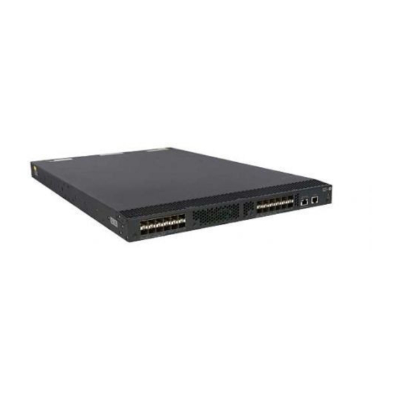
HP 5920 Switch Series Installation Manual
Hide thumbs
Also See for 5920 Switch Series:
- Command reference manual (607 pages) ,
- Configuration manual (424 pages) ,
- Fc and fcoe configuration manual (257 pages)

Related Manuals for HP 5920 Switch Series


Summary of Contents for HP 5920 Switch Series
-
Page 1: Installation Guide
HP 5920&5900 Switch Series Installation Guide 5998-2852 Part number: 5998-2852 Document version: 6W102-20131130... - Page 2 The only warranties for HP products and services are set forth in the express warranty statements accompanying such products and services. Nothing herein should be construed as constituting an additional warranty.
-
Page 3: Table Of Contents
Contents Preparing for installation ············································································································································· 1 Safety recommendations ·················································································································································· 2 Examining the installation site ········································································································································· 3 Temperature/humidity ············································································································································· 3 Cleanness ·································································································································································· 3 EMI ············································································································································································· 4 Laser safety ································································································································································ 4 Installation tools ································································································································································· 4 ... - Page 4 Garbled terminal display ······································································································································ 35 Appendix A Chassis views and technical specifications ························································································ 36 Chassis views ································································································································································· 36 HP 5920AF-24XG/HP 5920AF-24XG TAA ······································································································ 36 HP 5900AF-48XG-4QSFP+/HP 5900AF-48XG-4QSFP+ TAA/HP 5900CP-48XG-4QSFP+/HP 5900CP-48XG-4QSFP+8Gb FC B-F ··················································································································· 37 HP 5900AF-48XGT-4QSFP+ ································································································································ 38 ...
-
Page 5: Preparing For Installation
Preparing for installation Table 1 describes the HP 5920 and 5900 Switch Series models and power supplies. Table 1 HP 5920 and 5900 Switch Series models and power supplies Product code HP description Alias HP 5920 switches: JG296A HP 5920AF-24XG Switch... -
Page 6: Safety Recommendations
5900AF-48XG-4QSFP+ TAA products are assigned Regulatory Model Numbers (RMN). The Regulatory Model Numbers for these products are listed below. These regulatory numbers should not be confused with the marketing names HP 5900AF, or product numbers JC772A and JG554A. Product code... -
Page 7: Examining The Installation Site
• damaging the units. Examining the installation site The HP 5920 and 5900 switches must be used indoors. Mount your switch in a rack and make sure: • Adequate clearance is reserved at the air inlet and exhaust vents for ventilation. -
Page 8: Emi
WARNING! Do not stare into any fiber port when the switch has power. The laser light emitted from the optical fiber might hurt your eyes. The HP 5920 and 5900 switches are Class 1 laser devices. Installation tools Phillips screwdriver •... -
Page 9: Installing The Switch
Keep the tamper-proof seal on a mounting screw on the chassis cover intact, and if you want to open the chassis, contact HP for permission. Otherwise, HP shall not be liable for any consequence caused thereby. Figure 1 Hardware installation flow... -
Page 10: Mounting Bracket And Rack Mounting Rail Kits
(optional) Mounting bracket and rack mounting rail kits Every HP 5920 and 5900 switch comes with a pair of mounting brackets and a rack mounting kit that includes a pair of chassis rails and a pair of slide rails. See... -
Page 11: Rack-Mounting Procedures At A Glance
Attaching the mounting brackets, chassis rails, and grounding cable to the chassis Each of the HP 5920 and 5900 switches has one front mounting position (near the network ports) and one rear mounting position (near the power supplies). Each of the HP 5920AF-24XG and 5920AF-24XG TAA switches has one primary grounding point (with... - Page 12 (1) Rear mounting position (2) Primary grounding point (3) Auxiliary grounding point 1 (4) Front mounting position Figure 6 Mounting and grounding positions of the HP 5900AF-48XG-4QSFP+/5900AF-48XG-4QSFP+ TAA/5900CP-48XG-4QSFP+/5900CP-48XG-4QSFP+8Gb FC B-F/5900AF-48XGT-4QSFP+ (1) Auxiliary grounding point 2 (2) Rear mounting position (3) Primary grounding point...
- Page 13 NOTE: HP recommends that you use the primary grounding point or auxiliary grounding point 1 because the • grounding cable and grounding screw that come with the switch are suitable only for these two grounding points.
-
Page 14: Attaching The Slide Rails To The Rack
Choose a grounding point. Unpack the grounding cable and grounding screws. You can use the cable and screws shipped with the switch only for connecting to the primary grounding point or auxiliary grounding point 1. Align the two-hole grounding lug at one end of the cable with the grounding holes of the grounding point, insert the grounding screws into the holes, and tighten the screws with a screwdriver to attach the grounding lug to the chassis, as shown in Figure... -
Page 15: Mounting The Switch In The Rack
Identify the rack attachment position for the slide rails. Install cage nuts (user-supplied) in the mounting holes in the rack posts. Align the screw holes in one slide rail with the cage nuts in the rack post on one side, and use screws (user supplied) to attach the slide rail to the rack, as shown in Figure Repeat the preceding step to attach the other slide rail to the rack post on the other side. -
Page 16: Grounding The Switch
Figure 11 Mounting the switch in the rack (1) Figure 12 Mounting the switch in the rack (2) Grounding the switch WARNING! Correctly connecting the switch grounding cable is crucial to lightning protection and EMI protection. -
Page 17: Grounding The Switch With A Grounding Strip
The power input end of the switch has a noise filter, whose central ground is directly connected to the chassis to form the chassis ground (commonly known as PGND). You must securely connect this chassis ground to the earth so the faradism and leakage electricity can be safely released to the earth to minimize EMI susceptibility of the switch. -
Page 18: Grounding The Switch By Using The Ac Power Cord
NOTE: HP recommends that you use the primary grounding point or auxiliary grounding point 1, because the • grounding cable and grounding screw provided with the switch are applicable only to these two grounding points. To use auxiliary grounding point 2 on the HP 5900AF-48XG-4QSFP+, 5900AF-48XG-4QSFP+ TAA, •... -
Page 19: Installing/Removing A Fan Tray
Installing/removing a fan tray CAUTION: Every HP 5920 and 5900 switch requires two same direction air flow fan trays to function correctly. Do not operate the system with one failed fan tray for more than 24 hours. •... -
Page 20: Removing A Fan Tray
Figure 15 Installing an LSWM1FANSC/LSWM1FANSCB/LSWM1HFANSC/LSWM1HFANSCB fan tray (to the HP 5900AF-48XG-4QSFP+) Figure 16 Installing an LSVM1FANSC/LSVM1FANSCB fan tray to the HP 5920AF-24XG Removing a fan tray WARNING! Take out the fan tray after the fans completely stop rotating. • To avoid an unbalanced fan causing loud noise, do not touch the fans, even if they are not rotating. -
Page 21: Installing/Removing A Power Supply
The switches do not support intermixing of AC and DC power supplies. The HP 5920 and 5900 switches come with both power supply slots empty and the power filler modules as accessories. You can install one or two power supplies for these switches as needed. For more information about the power supplies available for the switches, see "Hot swappable power... -
Page 22: Removing A Power Supply
Figure 19 Installing a power supply Figure 20 Installing a power filler module Removing a power supply CAUTION: If the switch has two power supplies, removing one power supply does not affect the operation of the switch. If the switch has only one power supply, removing the power supply powers off the switch. To remove a 650W AC or DC power supply from the switch: Wear an ESD wrist strap and make sure it makes good skin contact and is well grounded. - Page 23 Figure 21 Removing the DC power cord (1) Press the tabs on the power cord connector with (2) Pull the power cord connector out your thumb and forefinger Figure 22 Removing the power supply (1) Pivot the latch to the right with your thumb (2) Pull the power supply out...
-
Page 24: Connecting The Power Cord
Connecting the power cord Connecting the 650W AC power supply Insert the female connector of the AC power cord supplied with the power supply into the power receptacle on the power supply. Use a cable tie to secure the power cord to the handle of the power supply, as shown in Figure Connect the other end of the power cord to an AC power outlet. -
Page 25: Verifying The Installation
Verifying the installation After you complete the installation, verify that: There is enough space for heat dissipation around the switch, and the rack is stable. • • The grounding cable is securely connected. The correct power source is used. • The power cords are correctly connected. -
Page 26: Accessing The Switch For The First Time
Accessing the switch for the first time Setting up the configuration environment The first time you access the switch you must use a console cable to connect a console terminal, for example, a PC, to the console port on the switch. Figure 25 Connecting the console port to a terminal Connecting the console cable Console cable... -
Page 27: Setting Terminal Parameters
Plug the DB-9 female connector of the console cable to the serial port of the PC. Connect the RJ-45 connector to the console port of the switch. NOTE: Identify the mark on the console port and make sure you are connecting to the correct port. •... - Page 28 Set Bits per second to 9600, Data bits to 8, Parity to None, Stop bits to 1, and Flow control to None, and click OK. Figure 29 Setting the serial port parameters Select File > Properties in the HyperTerminal window. Figure 30 HyperTerminal window...
- Page 29 On the Settings tab, set the emulation to VT100 and click OK. Figure 31 Setting terminal emulation in Switch Properties dialog box...
-
Page 30: Powering On The Switch
After the startup completes, you can access the CLI to configure the switch. For more information about the configuration commands and CLI, see HP 5920 & 5900 Switch Series Configuration Guide and HP 5920 & 5900 Switch Series Command References. -
Page 31: Setting Up An Irf Fabric
Setting up an IRF fabric You can use HP IRF technology to connect and virtualize HP 5920 and 5900 switches into a large virtual switch called an "IRF fabric" for flattened network topology, and high availability, scalability, and manageability. To set up IRF links between HP 5920 and 5900 switches, use SFP+ ports, 1/10-GE Ethernet ports, or QSFP+ ports. -
Page 32: Planning Irf Fabric Setup
NOTE: As your business grows, you can plug an HP 5920 or 5900 switch into an IRF fabric to increase the switching capacity without any topology change or replacement. Identifying the master switch and planning IRF member IDs Determine which switch you want to use as the master for managing all member switches in the IRF fabric. -
Page 33: Planning Irf Topology And Connections
1/10-GE Ethernet ports or QSFP+ ports. You can bind several 1/10-GE Ethernet ports or QSFP+ ports to an IRF port for increased bandwidth and availability. The HP 5920AF-24XG, and 5920AF-24XG TAA switches can provide 10-GE IRF connections through SFP+ ports. You can bind several SFP+ ports to an IRF port for increased bandwidth and availability. -
Page 34: Identifying Physical Irf Ports On The Member Switches
All the SFP+ and QSFP+ ports on the HP 5900AF-48XG-4QSFP+, 5900AF-48XG-4QSFP+ TAA, 5900CP-48XG-4QSFP+, 5900CP-48XG-4QSFP+8Gb FC B-F, and 5900AF-48G-4XG-2QSFP+ switches, all the 1/10-GE Ethernet ports and QSFP+ ports on the HP 5900AF-48XGT-4QSFP+ switch, and all the SFP+ ports on the HP 5920AF-24XG and 5920AF-24XG TAA switches can be used for IRF connections. - Page 35 For the HP 5900AF-48XGT-4QSFP+ switches, use twisted pair cables, QSFP+ cables, or QSFP+ transceiver modules and fibers to connect the IRF member switches. If the IRF member switches are far away from one another, choose the SFP+/QSFP+ transceiver modules with optical fibers. If the IRF member switches are all in one equipment room, choose twisted pair/SFP+/QSFP+ cables.
-
Page 36: Configuring Basic Irf Settings
Create a Layer 3 interface, assign it an IP address, and make sure the IRF fabric and the remote network management station can reach each other. Use Telnet, web, or SNMP to access the IRF fabric from the network management station. See HP 5920 & 5900 Switch Series Fundamentals Configuration Guide. - Page 37 To avoid IP address collision and network problems, configure at least one multi-active detection (MAD) mechanism to detect the presence of multiple identical IRF fabrics and handle collisions. For more HP 5920 & 5900 Switch Series IRF Configuration Guide information about MAD detection, see...
-
Page 38: Maintenance And Troubleshooting
Power supply failure You can use the LEDs on the power supply to identify a power supply failure. For more information about the LEDs on a power supply, see HP A58x0AF 650W AC (JC680A) & 650W DC (JC681A) Power Supplies User Guide. -
Page 39: Garbled Terminal Display
If the configuration terminal displays nothing when the switch is powered on, verify the following items: The power supply is supplying power to the switch. • • The console cable is correctly connected. The console cable has no problem and the terminal settings are correct. •... -
Page 40: Appendix A Chassis Views And Technical Specifications
"Installing/removing a power supply." The HP 5920AF-24XG and 5920AF-24XG TAA switches also come with the fan tray slots empty. You must install two fan trays for the 5920AF-24XG and 5920AF-24XG TAA for adequate heat dissipation, and their models must be the same. In this figure, two LSVM1FANSC fan trays are installed. For more information about installing and removing the fan tray, see "Installing/removing a fan... -
Page 41: 5900Cp-48Xg-4Qsfp+8Gb Fc B-F
(9) ACT LED for the management Ethernet port (10) USB port The HP 5900AF-48XG-4QSFP+, 5900AF-48XG-4QSFP+ TAA, 5900CP-48XG-4QSFP+, and 5900CP-48XG-4QSFP+8Gb FC B-F switches come with the power supply slots empty and the filler modules for the slots as accessories. You can install one or two power supplies for the switch as needed. -
Page 42: Hp 5900Af-48Xgt-4Qsfp
"Installing/removing a power supply." The HP 5900AF-48XG-4QSFP+, 5900AF-48XG-4QSFP+ TAA, 5900CP-48XG-4QSFP+, and 5900CP-48XG-4QSFP+8Gb FC B-F switches also come with the fan tray slots empty. You must install two fan trays for the 5900AF-48XG-4QSFP+, 5900AF-48XG-4QSFP+ TAA, 5900CP-48XG-4QSFP+, and 5900CP-48XG-4QSFP+8Gb FC B-F for adequate heat dissipation, and their models must be the same. -
Page 43: Hp 5900Af-48G-4Xg-2Qsfp
"Installing/removing a power supply." The HP 5900AF-48XGT-4QSFP+ switch also comes with the fan tray slots empty. You must install two fan trays for the 5900AF-48XGT-4QSFP+ for adequate heat dissipation, and their models must be the same. Figure 48, two LSWM1HFANSC fan trays are installed. -
Page 44: Technical Specifications
"Installing/removing a power supply." The HP 5900AF-48G-4XG-2QSFP+ switch also comes with the fan tray slots empty. You must install two fan trays for the 5900AF-48G-4XG-2QSFP+ for adequate heat dissipation, and their models must be the same. In Figure 48, two LSWM1FANSC fan trays are installed. - Page 45 5900AF-48XG-4Q SFP+/HP 5900AF-48XG-4Q 5920AF-24XG/HP Item SFP+ TAA/HP 5900AF-48G-4XG 5900AF-48XGT-4 5920AF-24XG 5900CP-48XG-4Q -2QSFP+ QSFP+ SFP+/HP 5900CP-48XG-4Q SFP+8Gb FC B-F 10/100/100 0Base-T autosensing Ethernet ports 1/10GBase-T autosensing Ethernet ports 2, hot swappable, 2, hot swappable, 2, hot swappable, 2, hot swappable, Fan tray slots...
- Page 46 5900AF-48XG-4Q SFP+/HP 5900AF-48XG-4Q 5920AF-24XG/HP Item SFP+ TAA/HP 5900AF-48G-4XG 5900AF-48XGT-4 5920AF-24XG 5900CP-48XG-4Q -2QSFP+ QSFP+ SFP+/HP 5900CP-48XG-4Q SFP+8Gb FC B-F Chassis UL60950-1, UL60950-1, UL60950-1, UL60950-1, leakage EN60950-1, EN60950-1, EN60950-1, EN60950-1, current IEC60950-1, IEC60950-1, IEC60950-1, IEC60950-1, compliance GB4943 GB4943 GB4943 GB4943 Melting 10 A @ 250 VAC...
-
Page 47: Appendix B Frus And Compatibility Matrixes
Appendix B FRUs and compatibility matrixes This appendix describes the field replaceable units (FRUs) available for the HP 5920 and 5900 Switch Series and their compatibility. All the FRUs in this appendix are hot swappable. Hot swappable power supplies Power supply... - Page 48 Maximum power consumption 60 W Documentation reference HP LSWM1HFANSC & LSWM1HFANSCB Installation Manual LSVM1FANSC ( for the HP 5920AF-24XG and 5920AF-24XG TAA switches) Fans Three 40 × 40 × 28 mm (1.57 × 1.57 × 1.1 in) fans Fan speed 18500 R.P.M...
- Page 49 Item Specifications LSVM1FANSCB ( for the HP 5920AF-24XG and 5920AF-24XG TAA switches) Fans Three 40 × 40 × 28 mm (1.57 × 1.57 × 1.1 in) fans Fan speed 18500 R.P.M Max airflow 57 CFM Front to back Airflow direction (Fans draw air from the network port side to the power supply side.)
-
Page 50: Appendix C Ports And Leds
PC running terminal emulation program. Management Ethernet port Every HP 5920 and 5900 switch has one management Ethernet port. You can connect this port to a PC or management station for loading and debugging software or remote management. Table 7 Management Ethernet port specifications... -
Page 51: Sfp+ Port
NOTE: USB devices from different vendors vary in compatibility and driver. HP does not guarantee correct operation of USB devices from other vendors on the switch. If a USB device does not operate correctly on the switch, replace it with one from another vendor. - Page 52 For the most up-to-date list of SFP transceiver modules, consult your HP sales representative or technical support engineer. For the SFP transceiver module specifications, see HP A-Series Switches Transceiver Modules User Guide. The SFP+ cables available for the HP 5920 and 5900 Switch Series are 10 Gbps SFP+ Cu cables, as shown in Figure...
-
Page 53: Qsfp+ Port
(1) Connector (2) Pull latch QSFP+ port HP 5900 switches provide QSFP+ ports. You can plug the QSFP+ transceiver modules in Table 1 1 the QSFP+ cables in Table 12 into the SFP+ ports as needed. Table 11 QSFP+ transceiver modules available for the HP 5900 switches... -
Page 54: 10/100/1000Base-T Autosensing Ethernet Port
(3) SFP+ side pull latch (4) SFP+ module NOTE: To guarantee the functionality of the QSFP+ ports, use only HP QSFP+ transceiver modules and cables. • The QSFP+ transceiver modules and cables available for this switch series are subject to change over •... -
Page 55: 1/10Gbase-T Autosensing Ethernet Port
IEEE 802.3ab Compatible standards • IEEE 802.3an To avoid interference between cables, HP recommends that you layer cables as follows: Use category-6A or above twisted pair cables and connectors. • Do not bundle cables in their first 20 m (65.62 ft). -
Page 56: Sfp+ Port Led
LED mark Status Description Flashing green The switch is performing power-on self test (POST). The system has failed to pass POST or has problems such as Steady red fan failure. Flashing red Some ports have failed to pass POST. The switch is powered off or has failed to start up. SFP+ port LED Each SFP+ port has a status LED to show port operating status and activities. -
Page 57: 10/100/1000Base-T Autosensing Ethernet Port Leds
Table 18 Management Ethernet port LEDs description LED mark Status Description The management Ethernet port is not connected. LINK Steady green The management Ethernet port is operating at 10/100/1000 Mbps. The management Ethernet port is not receiving or sending data. Flashing yellow The management Ethernet port is sending or receiving data. -
Page 58: Appendix D Cooling System
Appendix D Cooling system The cooling system of the HP 5920 and 5900 switches comprises the ventilation holes in the chassis, fan trays, and built-in fans of hot swappable power supplies. To guarantee that this cooling system can effectively work, you must consider the site ventilation design when you plan the installation site for the switches. -
Page 59: Hp 5900 Cooling System
The fan trays in the HP 5900AF-48XG-4QSFP+, 5900AF-48XG-4QSFP+ TAA, 5900CP-48XG-4QSFP+, 5900CP-48XG-4QSFP+8Gb FC B-F, and 5900AF-48G-4XG-2QSFP+ switches must be the same type: LSWM1FANSC or LSWM1FANSCB. The fan trays in the HP 5900AF-48XGT-4QSFP+ switch must be the same type: LSWM1HFANSC or LSWM1HFANSCB. •... - Page 60 Figure 55 Airflow through the HP 5900AF-48XG-4QSFP+ chassis (with LSWM1FANSC fan trays) (1) Power supply air vents (2) Fan tray air vents (3) Network port-side air vents Figure 56 Airflow through the HP 5900AF-48XG-4QSFP+ chassis (with LSWM1FANSCB fan trays) (1) Power supply air vents...
-
Page 61: Support And Other Resources
Related information Documents To find related documents, browse to the Manuals page of the HP Business Support Center website: http://www.hp.com/support/manuals • For related documentation, navigate to the Networking section, and select a networking category. -
Page 62: Conventions
Conventions This section describes the conventions used in this documentation set. Command conventions Convention Description Boldface Bold text represents commands and keywords that you enter literally as shown. Italic Italic text represents arguments that you replace with actual values. Square brackets enclose syntax choices (keywords or arguments) that are optional. Braces enclose a set of required syntax choices separated by vertical bars, from which { x | y | ... - Page 63 Represents a generic network device, such as a router, switch, or firewall. Represents a routing-capable device, such as a router or Layer 3 switch. Represents a generic switch, such as a Layer 2 or Layer 3 switch, or a router that supports Layer 2 forwarding and other Layer 2 features.
-
Page 64: Index
Examining the installation site,3 Related information,57 failure,34 Safety recommendations,2 Setting terminal parameters,23 Grounding the switch,12 Setting up the configuration environment,22 Hot swappable fan trays,43 Technical specifications,40 Hot swappable power supplies,43 HP 5900 cooling system,55 HP 5920 cooling system,54 Verifying the installation,21...