Buderus LOGANO PLUS GB312 Installation Instructions Manual
Gas condensing boiler
Hide thumbs
Also See for LOGANO PLUS GB312:
- Installation manual (124 pages) ,
- Installation and service instructions manual (96 pages) ,
- Installation and maintenance instructions manual (76 pages)
Table of Contents
Advertisement
Quick Links
Installation and Service
Instructions
Logano plus GB312
Gas condensing boiler
CAUTION!
Observe the safety instructions of this installation
and maintenance manual before placing the boiler
in operation.
DANGER!
If installation, adjustment, modification, operation or
maintenance of the heating system is carried out by an
unqualified person, this may result in danger to life and
limb or property damage.The installation and servicing
instructions must be followed precisely.
Contact a qualified service company, service provider
or the gas company if support or additional information
is required.
DANGER!
The operating manual is a component of the technical
documentation and must be handed over to the operator
of the heating system. Discuss the instruction in this
manual with the owner or operator of the heating system
to ensure that they are familiar with all information required
for operation of the heating system. If the storage tank will
be installed in Massachusetts, it must be installed by an
installer or dealer who is registered there.
C
Advertisement
Table of Contents
Troubleshooting

Related Manuals for Buderus LOGANO PLUS GB312


Summary of Contents for Buderus LOGANO PLUS GB312
- Page 1 If the storage tank will be installed in Massachusetts, it must be installed by an installer or dealer who is registered there. Logano plus GB312...
-
Page 2: Table Of Contents
Starting up the controls and the burner with RC35 2.10.1 Logano plus GB312 dimensions ....10 programming unit ......34 2.10.2 Specifications . -
Page 3: Table Of Contents
List of keywords ........93 Logano plus GB312 – 6 720 647 367 (2012/11) -
Page 4: General Safety Instructions And Explanation Of Symbols
▶ It is not sufficient just to switch off the control unit. ▶ Take measures to ensure that the heating system cannot be switched on again unintentionally. Logano plus GB312 – 6 720 647 367 (2012/11) - Page 5 ▶ Use original spare parts only. No liability is assumed for damage caused by the use of spare parts not supplied by Buderus. Installation and adjustment ▶ Correct and proper installation and adjustment of the burner and the control panel are the fundamental requirements for safe and economical operation of the boiler.
-
Page 6: Product Description
Correct use installed by a licensed plumber and gas fitter. Valves external to the The Logano plus GB312 is designed for heating central heating system boiler must be fitted with T-handles and condensate piping must be water and, with the use of an indirect tank, domestic hot water, for installed in accordance with the State Plumbing Code. -
Page 7: Notes On Installation And Operation
BC10 controls. This value can be increased but not reduced. ▶ If an external controller controls the recirculation pump, a pump post purge time of 5 minutes must be ensured. Logano plus GB312 – 6 720 647 367 (2012/11) -
Page 8: Product Description
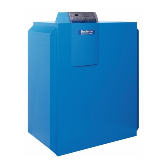
Product description Product description The Logano plus GB312 ( Fig. 1) is supplied with a fully factory-fitted and ready-wired Logamatic BC10 basic programming unit ( Fig. 2, page 9). 7 747 010 720-01.3RS Fig. 1 Logano plus GB312 - main components... -
Page 9: Scope Of Delivery
Fig. 2 Controls on the Logamatic BC10 base controller On-off switch Scope of delivery Dial for DHW set point The Logano plus GB312 is supplied as standard with a Logamatic BC10 LED "DHW status" base controller and the MC10 control unit. Status display ▶... -
Page 10: Dimensions And Specifications
Product description 2.10 Dimensions and specifications 2.10.1 Logano plus GB312 dimensions Fig. 3 Connections and dimensions for Logano plus GB312 (sizes in inches) [AA] = Flue connection [AL] = Combustion air pipe connection (sealed combustion operation only) [VK] = Boiler supply... -
Page 11: Specifications
Fig. 4 (graph) Primary pressure drop Maximum flow temperature, heating/hot water mode ° F 180/180 High temperature cut-out safety limit ° F (manual reset high limit setting) Table 3 Specifications Logano plus GB312 – 6 720 647 367 (2012/11) - Page 12 200 - 6 720.6 240 - 7 868.8 280 - 8 1013.4 Table 4 Gas flow rate (based on gas temperature of 60 °F and air pressure of 30 ins Hg) Logano plus GB312 – 6 720 647 367 (2012/11)
-
Page 13: Transporting The Boiler
▶ Unscrew the locking screws from the side panels at the front and back of the boiler. 7 747 010 720-06.1RS Fig. 6 Lifting the boiler off the pallet. Locking screw Pallet Logano plus GB312 – 6 720 647 367 (2012/11) -
Page 14: Transporting The Boiler On Rollers
Fig. 7 Transporting the boiler using pipes Positions for securing the boiler against slipping Pipe (for carrying) 7 747 010 720-08.1RS Fig. 8 Transporting the boiler on rollers (dimensions in inches) Logano plus GB312 – 6 720 647 367 (2012/11) -
Page 15: Installing The Boiler
7 747 010 720-10.1RS Fig. 10 Leveling the boiler Adjustable feet Level Logano plus GB312 – 6 720 647 367 (2012/11) -
Page 16: Openings For Combustion Air Supply And Venting
CAUTION: Dangers posed by explosive and easily combustible materials. ▶ Do not use or store easily-combustible materials (paper, lace curtains, clothing, thinners, paints, etc.) near the boiler. ▶ Maintain a clearance of 16 inches from the boiler. Logano plus GB312 – 6 720 647 367 (2012/11) -
Page 17: Installing The Boiler
Section 6.5, page 20) must be designed for a max. pressure of requirements about carbon monoxide detectors must be 0.40 inches W.C. for the overall system (flue and air supply system). followed. Logano plus GB312 – 6 720 647 367 (2012/11) -
Page 18: Connecting The Flue Pipe To The Boiler
Dripping condensate can result in ice foot) from the boiler. formation on the footway. 7 747 010 720-11.2RS Fig. 11 Connecting the flue Flue pipe adaptor (available separately) Flue pipe adaptor (available separately) Fitted gasket Logano plus GB312 – 6 720 647 367 (2012/11) -
Page 19: Installing The Wall Termination For A Horizontal Flue
Minimum vertical distance from air intake of another appliance = 3 ft, with directly vented appliances the flue outlet can be positioned level with the appliance's own air intake (observe minimum horizontal separation of 4 ft). Logano plus GB312 – 6 720 647 367 (2012/11) -
Page 20: Installation Of The Roof Penetration Of A Vertical Flue System
For details of correct dimensioning, contact the Fastening the flue pipe manufacturer concerned. Flue pipe adaptor (available separately) Fig. 15 Connecting the air supply for balanced flue operation Screw Cover plate Logano plus GB312 – 6 720 647 367 (2012/11) -
Page 21: Installing The Combustion Air Wall Termination
Buderus can not be held responsible for such 3 ft min. 6 720 647 031-01.1T Fig. -
Page 22: Installing The Combustion Air Roof Termination
Buderus can not be held responsible for such adequate for specific installations. -
Page 23: Design Of Flue And Air Pipe For Direct Vent Operation
[1;2] Flue termination (external-wall flue requires horizontally Air inlet (90° elbow or T-piece) or vertically mounted T-piece), observe clearances specified External wall in Fig. 12 Roof Air intake terminal (90° elbow facing vertically downwards) External wall Logano plus GB312 – 6 720 647 367 (2012/11) -
Page 24: Connecting The Heating System
▶ Make sure that if the boiler is located above the level of the heating system, it is fitted with a low-water cut- off. ▶ The low-water indicator must be used when the boiler is installed ( Fig. 22). Logano plus GB312 – 6 720 647 367 (2012/11) -
Page 25: Connecting The Boiler To The Heating System
Fitting an automatic air vent to the B-kit on the flow pipe is recommended. ▶ Fit and seal the safety valve in the connection provided using the NPT double union supplied ( Figs. 23 and 24). Logano plus GB312 – 6 720 647 367 (2012/11) -
Page 26: Connecting The Central Heating Supply
▶ Make sure that the washer and seal are properly Threaded flange seated in the cap. Non-return check valve (observe direction of flow) Washer ▶ Refit the trap. [VK] Boiler flow Logano plus GB312 – 6 720 647 367 (2012/11) -
Page 27: Filling The Heating System And Checking For Water Leaks
▶ Open the mixing and shut-off valves on the heating water (primary) side. Logano plus GB312 – 6 720 647 367 (2012/11) -
Page 28: Connecting The Fuel Supply
Gas supply Manual shut-off valve (supplied) Sediment trap Gas connection with isolating valve 7 747 010 720-25.1RS Fig. 29 Boiler fill & drain valve on return pipe Boiler fill & drain valve Logano plus GB312 – 6 720 647 367 (2012/11) -
Page 29: Installation At High Altitudes
▶ Do not spray leak detector onto cable conduits, plugs or electrical connecting leads or allow it to drip onto Contact Buderus if the installation site is at a high them. altitude. The boiler must only be adjusted as specified in the relevant technical documentation and using the adjusting procedure approved by Buderus. - Page 30 7 747 010 720-35.1RS Fig. 35 Fitting the cover 7 747 010 720-33.1RS Fig. 33 Removing the cover ▶ Always check that the heating system is working properly after carrying out any servicing work. Logano plus GB312 – 6 720 647 367 (2012/11)
-
Page 31: Leveling The Boiler
▶ If the information in this manual is not followed exactly, a fire or explosion may result causing property damage, personal injury or loss of life. ▶ It is imperative that the commissioning instructions are followed! Logano plus GB312 – 6 720 647 367 (2012/11) -
Page 32: Checking The Operating Pressure
Fig. 38 Topping up heating water/draining via the boiler fill & drain valve water used to fill the system in the operator’s log. Boiler fill & drain valve Water quality must be checked each year. Logano plus GB312 – 6 720 647 367 (2012/11) -
Page 33: Checking For Leaks
▶ Check that the flue pipe connection complies with the applicable regulations ( Section 6.8, page 23). ▶ Check that the flue pressure does not exceed the available pressure of 0.4 inches W.C. (100 Pa). Logano plus GB312 – 6 720 647 367 (2012/11) -
Page 34: Making The Heating System Ready For Operation
▶ Continue commissioning procedure as described in Section 7.9.3. programming unit for information on how to do so. 7.9.2 Boiler intended to be used with RC35 ▶ Use the RC35 programming unit. Logano plus GB312 – 6 720 647 367 (2012/11) -
Page 35: Switching On The Boiler On The Bc10
37) into the centre of the gas flow. ▶ Measure the pressure in the flue using a suitable pressure tester (for location of testing point, see Fig. 47, page 37). Logano plus GB312 – 6 720 647 367 (2012/11) -
Page 36: Content, Natural Gas Type A
– Flue pressure – Flue gas temperature t – Carbon dioxide content (CO )or oxygen content (O – Carbon monoxide content (CO) 7 747 010 720-42.2RS Fig. 45 Setting medium output Logano plus GB312 – 6 720 647 367 (2012/11) -
Page 37: Switching The Status Display On The Bc10 To Show The Boiler Temperature Status
– If the gas supply dynamic pressure is too high, install an additional ▶ Identify and eliminate the fault. gas pressure regulator upstream of the gas valve. ▶ Remove the pressure gauge hose. Logano plus GB312 – 6 720 647 367 (2012/11) -
Page 38: Checking For Leaks During Operation
▶ To avoid corrosion, carefully wipe off the leak to do in an emergency, e.g. a fire. detector afterwards. Hand over the technical documentation to the owner/operator and then both sign the commissioning log ( Section 7.20, page 39). Logano plus GB312 – 6 720 647 367 (2012/11) -
Page 39: Commissioning Log
Readings taken Remarks Fill heating system and check for leaks – Heating system filling pressure ____________ psi Details in "Water quality requirements for Logano plus GB312" manual taken into account – Concentration of any additives Add.:______ Conc.:___% Record gas characteristics: calorific value _________ BTU/ft³... -
Page 40: Shut Down The Heating System
Turn off the heating system on the Logamatic BC10 basic control unit. When the Logamatic BC10 basic control unit is switched off, the burner Spare parts can be ordered from Buderus using the parts is automatically shut down at the same time. For more detailed list. -
Page 41: General Operations
Before cleaning the burner or heat exchanger, carry out the following GB312" manual). tasks: ▶ Bleed the heating system while filling. ▶ Check the heating system for leaks. ▶ Check that the expansion vessel functions properly. Logano plus GB312 – 6 720 647 367 (2012/11) -
Page 42: Determining The Extent Of Contamination
SERVICE/DIAGNOSIS menu. ▶ Turn the rotary selector counter-clockwise to select monitor reading (indicated by SERVICE|DIAGNOSIS function test monitor reading diagnosis servicing Fig. 55 Switching on the basic control unit Fig. 58 Logano plus GB312 – 6 720 647 367 (2012/11) -
Page 43: Cleaning The Burner And Heat Exchanger
▶ Unscrew the fixing nuts (3) from the top and bottom of the burner shield. ▶ Bolts (2) on the side of the fan: Undo the two rear hex-head bolts by two turns; remove the front two hex-head bolts. Logano plus GB312 – 6 720 647 367 (2012/11) - Page 44 Short cleaning blade (available separately) 7 747 010 720-28.2RS Fig. 63 Opening the cleaning covers Cleaning cover on heat exchanger Fixing nuts on cleaning cover Condensate pan cover Fixing nuts on the condensate pan cover Logano plus GB312 – 6 720 647 367 (2012/11)
- Page 45 ▶ Blow-clean the burner rods and manifold from inside and outside with compressed air. 7 747 010 720-31.1RS Fig. 65 Wet cleaning the heat exchanger 7 747 010 720-72.1RS Fig. 67 Cleaning the burner Burner rods Logano plus GB312 – 6 720 647 367 (2012/11)
- Page 46 Fig. 68 Checking electrode position Burner rod Ionization electrode Ignition electrode 7 747 010 720-75.1RS Fig. 70 Checking that the gasket is in place Indicator window on flange Vent flange Logano plus GB312 – 6 720 647 367 (2012/11)
-
Page 47: Checking Gas Valve For Leaks
90-4 to 240-7, and 7 (equates to 0.01 ft /h) for boiler size 280-8. ▶ Remove the testing nipples from testing points 3 and 4 and carefully refit and seal the blanking plugs using an appropriate sealant. Logano plus GB312 – 6 720 647 367 (2012/11) - Page 48 Gas isolating valve on gas valve outlet side Manual isolating valve (testing apparatus) Manual isolating valve (testing apparatus) Hand pump (testing apparatus) Pressure tester (testing apparatus) Low pressure switch (available separately) [1, 2, 3, 4, P]Pressure testing points Logano plus GB312 – 6 720 647 367 (2012/11)
-
Page 49: Checking For Leaks During Normal Operation
9.10.2 Installing outer casing panels ▶ Refit outer casing panels ( Fig. 50, page 38). 9.10.3 Confirming servicing/maintenance ▶ Sign the servicing and maintenance log in this manual ( Section 9.11, page 50). Logano plus GB312 – 6 720 647 367 (2012/11) -
Page 50: Inspection And Maintenance Logs
Checking for leaks during operation Check that the programming unit settings are as required – (see programming unit documentation) Final check of servicing work – Confirmation of properly completed servicing Company stamp/Date/Signature Table 19 Logano plus GB312 – 6 720 647 367 (2012/11) - Page 51 ____% ____% ____% ____% ____% _____ ppm _____ ppm _____ ppm _____ ppm _____ ppm _____ ppm _____ ppm _____ ppm _______μA _______μA _______μA _______μA _______μA _______μA _______μA _______μA Table 20 Logano plus GB312 – 6 720 647 367 (2012/11)
-
Page 52: Troubleshooting
▶ Rectify the fault immediately and restart the heating system. ▶ If that is not possible, protect the heating system against freezing by draining the heating system and hot water pipes from the lowest point. Logano plus GB312 – 6 720 647 367 (2012/11) -
Page 53: Operating And Error Messages
Beginning of sequence for starting up burner. Beginning of burner start-up. Gas valve opening. Table 21 Operating codes 1) V = locking; B = inhibiting; BC = operating code Logano plus GB312 – 6 720 647 367 (2012/11) -
Page 54: Fault Messages
Replace lead if the set speed. contact, breaks and necessary. damage. Check connectors for Replace fan. damage. Table 22 Fault messages 1) V = locking; B = inhibiting; BC = operating code Logano plus GB312 – 6 720 647 367 (2012/11) - Page 55 (SAFe discrepancies. documentation). Replace SAFe if there are discrepancies. Table 22 Fault messages 1) V = locking; B = inhibiting; BC = operating code Logano plus GB312 – 6 720 647 367 (2012/11)
- Page 56 Check function of gas Replace gas valve. valve. Table 22 Fault messages 1) V = locking; B = inhibiting; BC = operating code Logano plus GB312 – 6 720 647 367 (2012/11)
-
Page 57: Ionization Current
The power supply voltage Ensure adequate power voltage is too low. must not drop below supply voltage. 102V. Table 22 Fault messages 1) V = locking; B = inhibiting; BC = operating code Logano plus GB312 – 6 720 647 367 (2012/11) - Page 58 (available separately) is Replacing the breaking circuit during gas valve operation Section 10.3, page 87 ff Table 22 Fault messages 1) V = locking; B = inhibiting; BC = operating code Logano plus GB312 – 6 720 647 367 (2012/11)
- Page 59 Check water pressure Replace water pressure sensor. sensor. Table 22 Fault messages 1) V = locking; B = inhibiting; BC = operating code Logano plus GB312 – 6 720 647 367 (2012/11)
- Page 60 Important: this fault can only be reset by the button on the SAFe. Table 22 Fault messages 1) V = locking; B = inhibiting; BC = operating code Logano plus GB312 – 6 720 647 367 (2012/11)
- Page 61 Eliminate voltage dips. occurring (e.g. when large electrical consumers are switched on) If all checks OK, replace SAFe. Table 22 Fault messages 1) V = locking; B = inhibiting; BC = operating code Logano plus GB312 – 6 720 647 367 (2012/11)
-
Page 62: Troubleshooting Safety Sequence/Pressure Switch
Switch boiler OFF and ON again on controller! Does Fault 8L / 579 recur? Replace low pressure switch (available separately) Fig. 74 Fault elimination sequence 8L/579 Logano plus GB312 – 6 720 647 367 (2012/11) - Page 63 Replace SAFe Perform reset! Does burner start up? pressure switch. Perform reset! Replace SAFe! Does burner start up? Fig. 75 Fault elimination sequence 8Y/590 Logano plus GB312 – 6 720 647 367 (2012/11)
- Page 64 Replace SAFe Perform reset! Does burner start up? pressure switch. Perform reset! Replace SAFe! Does burner start up? Fig. 76 Fault elimination sequence 8Y/591 Logano plus GB312 – 6 720 647 367 (2012/11)
-
Page 65: Sensor Characteristics
Resistance in k Ω Two identical "dual sensors" fitted in the sensor housing are used as high limit temperature sensors. All temperature sensors on the GB312 have the same sensor characteristic. Logano plus GB312 – 6 720 647 367 (2012/11) -
Page 66: Spare Parts
Pressure relief valve 3/4"Fx1"F 50PSI 90-280kW 7747017645 Temperature/pressure gauge WINTERS 1/2"M 7747016332 Available accessories for B-kit GB312 "US/CA": Low water indicator SAFGARD 3/4"M 7747016333 High temperature cut-off 3/4"M 7747016328 Table 23 Boiler heat exchanger Logano plus GB312 – 6 720 647 367 (2012/11) - Page 67 Appliance feet M10x51mm (set of 4) 5236440 Gasket set for boiler GB312 63037291 Comprising: O-ring Flat gasket D31/47x6 Shore 70 EPDM Glass fabric tape D48/63x0.25 PTFE coated Gasket D=40x2 SIL24 Table 23 Boiler heat exchanger Logano plus GB312 – 6 720 647 367 (2012/11)
- Page 68 Spare parts 7747101916-02-Kesselblock GB312 USA Fig. 78 Boiler heat exchanger Logano plus GB312 – 6 720 647 367 (2012/11)
- Page 69 Air socket cover GB312 63038962 Fascia panel G244/GB312 63037441 Cable conduit GB312 63038445 Panhead screw ST3.9x40 Panhead screw ST3.9x9.5 Blind rivet 4x8 St/St Cover panel US 7747018781 Table 24 Boiler outer casing Logano plus GB312 – 6 720 647 367 (2012/11)
- Page 70 Spare parts p l u 7747101917-01-Verkleidung GB312 USA Fig. 79 Boiler outer casing Logano plus GB312 – 6 720 647 367 (2012/11)
- Page 71 Cartridge fuse 6.3x32 10AT 125V/US a pack of 10 7747026156 BC10 basic control unit for UBA3 "US" 63033278 Outdoor temperature sensor FA 5991374 Module EM10 US 18358 Table 25 Heat insulation and programmer Logano plus GB312 – 6 720 647 367 (2012/11)
- Page 72 Spare parts E co A ut A ut 7747101918-00-Wärmeschutz und Regelung GB312 USA Fig. 80 Heat insulation and programmer Logano plus GB312 – 6 720 647 367 (2012/11)
- Page 73 Notice: if required order set of filter tubes NE 0.1 V2 Set of filter tubes NE 0.1 V2 (inserted) 63038062 Inlet/outlet connection NE 0.1 63015904 Hose 19x3.5x1000mm (condensate inlet) 7115124 (not illustrated) Table 26 Neutralizer Logano plus GB312 – 6 720 647 367 (2012/11)
- Page 74 Spare parts Fig. 81 Neutralizer Logano plus GB312 – 6 720 647 367 (2012/11)
- Page 75 Fan unit VM312-160 US EG 7747016631 Fan unit VM312-200 US EG 7747016632 Fan unit VM312-240 US EG 7747016633 Fan unit VM312-280 US EG 7747016634 Table 27 Burner variants, rating plate VM312 US Logano plus GB312 – 6 720 647 367 (2012/11)
- Page 76 Spare parts Output Leistung Ser.-Nr. 63038106-00-5194-000042 0031511501 7747101921-03-Brennervarianten, Typenschild VM312 US Fig. 82 Burner variants, rating plate VM312 US Logano plus GB312 – 6 720 647 367 (2012/11)
- Page 77 Available spare parts: Thermofix ceramic adhesive tube 115 g 2037312 Burner rod gasket VM312 63036119 Hex nut EN1661 M5 10 A3K with serrated washer 5834400 Table 28 Burner rods, heat shield VM312 US Logano plus GB312 – 6 720 647 367 (2012/11)
- Page 78 Spare parts 7747101922-01-Brennstab, Wärmeschutz VM312 US Fig. 83 Burner rods, heat shield VM312 US Logano plus GB312 – 6 720 647 367 (2012/11)
- Page 79 Bracket for inspection window glass Inspection window glass, Tempax 30x30x3.3mm 5447620 Inspection window seal DIN6921 M8x12 (12x) hexagon-head bolt 63036122 Burner bracket Burner bracket seal VM312-12 mm 63046223 Table 29 Manifold VM312 US Logano plus GB312 – 6 720 647 367 (2012/11)
- Page 80 Spare parts 7747101923-01-Verteilerrohr VM312 US Fig. 84 Manifold VM312 US Logano plus GB312 – 6 720 647 367 (2012/11)
- Page 81 Screw DIN7500CE M5x12 CombiTorx 63010217 Fan ebm G1G170-AB 120V60Hz 7747016669 Available spare part: Hexagon bolt DIN6921 M8x12 63036122 Burner bracket seal VM312-12 mm 63046223 Burner bracket Table 30 Igniter system, fan VM312 US Logano plus GB312 – 6 720 647 367 (2012/11)
- Page 82 Spare parts 7747101924-03-Zündung/Gebläse VM312 US Fig. 85 Igniter system, fan VM312 US Logano plus GB312 – 6 720 647 367 (2012/11)
- Page 83 Tester lead set VM312 US 7747016670 Comprising: Compensation lead VM312 US Union, Honeywell 5/4 Gas orifice D17 SW24 VM312 EG 7747026085 Venturi gasket VM312 63040179 Table 31 Air inlet, venturi VM312 US Logano plus GB312 – 6 720 647 367 (2012/11)
- Page 84 Spare parts 7747101925-02-Zuluft, Venturi VM312 US Fig. 86 Air inlet, venturi VM312 US Logano plus GB312 – 6 720 647 367 (2012/11)
- Page 85 O-ring 52.39 x 3.53 63036065 Ball valve DN25 RUBS92F41 1" 7747016685 Ball valve DN32 RUB S92G41 11/4" 7747016688 SAFe Pressure switch 7747021498 Table 32 Gas valve VR4730, gas connecting pipe VM312 US Logano plus GB312 – 6 720 647 367 (2012/11)
- Page 86 Spare parts 7747101926-03-Gasarmatur VR4730, Gasanschlussrohr VM312 US Fig. 87 Gas valve VR4730, gas connecting pipe VM312 US Logano plus GB312 – 6 720 647 367 (2012/11)
- Page 87 Connecting lead, flow/return sensor 63035355 Connecting lead with grommet, boiler sensor/SAFe BE 63039214 Data lead, SAFe/MC10 63034190 Connecting lead, MV1 burner UL 7747016588 Table 33 Safe 40 with connecting lead VM312 US Logano plus GB312 – 6 720 647 367 (2012/11)
- Page 88 Spare parts 7747101927-03-Safe 40 mit Anschlussleitungen VM312 US Fig. 88 Safe 40 with connecting lead VM312 US Logano plus GB312 – 6 720 647 367 (2012/11)
-
Page 89: Boiler Internal Wiring Diagram
Boiler internal wiring diagram Boiler internal wiring diagram Fig. 89 Boiler internal wiring diagram, gas boiler GB 312 USA/CD Logano plus GB312 – 6 720 647 367 (2012/11) -
Page 90: Examples Of Installations
Refer to GB312 Application Manual for additional system piping and wiring configurations. 14.1 Boiler, low-loss header, AM10 Fig. 90 Example of installation: Logano plus GB312, low-loss header, AM10. Schematic diagram, not necessarily representative of complete system. [FV] Flow temperature sensor... -
Page 91: Boiler, Low-Loss Header, Logamatic 4000
Examples of installations 14.2 Boiler, low-loss header, Logamatic 4000 Fig. 91 Example of installation: Logano plus GB312, low-loss header, Logamatic 4000. Schematic diagram, not necessarily representative of complete system. [FV] Flow temperature sensor [FW] DHW sensor [MAG]Diaphragm expansion vessel [PH] Heating system pump... -
Page 92: Boilers, Low-Loss Header, Logamatic 4000 With Fm456 Module
[SA] Branch equalizer valve [SH] Heating system adjuster (mixer) [THV] Thermostat PH = Differential pressure regulated pumps. The low-loss header (WH) should be fitted as close as possible to the boiler. Logano plus GB312 – 6 720 647 367 (2012/11) -
Page 93: List Of Keywords
....... Product description BC10 operating elements ..........RC35 user interface ..........Removing the burner ..............Safety ............ Safety instructions ..........Three-way diverter valve ............Transport ............Wall clearances ............Wet cleaning Logano plus GB312 – 6 720 647 367 (2012/11) - Page 94 Notes Logano plus GB312 – 6 720 647 367 (2012/11)
- Page 95 Notes Logano plus GB312 – 6 720 647 367 (2012/11)