Table of Contents
Advertisement
Quick Links
Download this manual
See also:
Quick Reference Manual
Advertisement
Table of Contents

Related Manuals for Kodak DCS 600 Series


Summary of Contents for Kodak DCS 600 Series
- Page 1 DCS 600 Series Digital Cameras User’s Guide for DCS 600 Series Digital Cameras...
- Page 2 © Eastman Kodak Company and Nikon Corp., 2000 All rights reserved Kodak and Kodak Professional are trademarks of Eastman Kodak Company Adobe, Photoshop, and Acrobat are trademarks of Adobe Systems Inc.
-
Page 3: Warranty Time Period
If this equipment does not function properly during the warranty period due to defects in material or workmanship, Kodak will, at its option, either repair or replace the equipment without charge, subject to the conditions and limitations stated herein. Such repair service will include all labor as well as any necessary adjustments and/or replacement parts. - Page 4 Kodak representative for return authorization and instructions. Should you need to return equipment to Kodak, Kodak is not responsible for the loss or damage of equipment while in transport to a Kodak authorized service center. You may, at your option, choose to insure equipment for loss or damage with the carrier of your choice.
-
Page 5: Outside The United States
In Canada, call 1-800-GO-KODAK (1-800-465-6325). In other countries, call your nearest Kodak representative. If service is required, your Kodak representative will instruct you to return the unit to the nearest service center for repair and will issue a return authorization number. -
Page 6: Product Support Options
Product Support Options During the warranty period for the Kodak Professional DCS 600 Series digital camera, you are entitled to product support for both hardware and software, provided your camera is registered with the Eastman Kodak Company. You may register with Eastman Kodak via mail, fax, or through Kodak’s WWW (World Wide Web) site... - Page 7 Out-of-Warranty Support Options There will be a charge for call incidents if you wish to speak to a Kodak support representative. A call incident is defined as only those issues raised during the first telephone or email contact. Follow-up telephone calls by Kodak’s representative, and callbacks to Kodak’s Support Center to resolve the call incident will not be charged,...
-
Page 8: Table Of Contents
Table of Contents Important Information ...1-1 System Requirements for your Computer... 1-2 Macintosh ... 1-2 Windows ... 1-2 Warnings ... 1-3 Important Safeguards and Precautions... 1-4 Electromagnetic Emissions ... 1-7 VCCI Statement ... 1-7 About Your Camera ...2-1 Nomenclature ... 2-3 Camera Front ... - Page 9 Top Status LCD Panel ... 2-11 Back Status LCD Panel ... 2-12 Image LCD Panel ... 2-12 Menu Bar ... 2-12 Navigation Techniques ... 2-14 Status Bar ... 2-16 Command Dials ... 2-17 Main-Command Dial ... 2-17 Rotating the Main-Command Dial by Itself ... 2-17 Rotating the Main-Command Dial While Pressing Buttons 2-18 Sub-Command-Dial ...
- Page 10 Sync Terminal ... 2-30 Self-Diagnostic Shutter System ... 2-31 Changing Viewfinders ... 2-32 Removing the Finder ... 2-32 Attaching the Finder ... 2-33 Changing Focusing Screens... 2-34 Camera Straps ... 2-35 Attaching the Neck Strap ... 2-35 Attaching the Hand Strap ... 2-36 Name Plate ...
- Page 11 Configuring Your Camera ... 4-1 Date and Time... 4-1 Camera Properties... 4-3 Setting Display Off Time ... 4-3 Setting PowerSave Time ... 4-3 Enabling Sharpening ... 4-4 Setting File Resolution ... 4-5 Determining Total Actuations ... 4-6 Use Folder 1 ... 4-6 Custom Settings ...
- Page 12 The AC Adapter for Camera ... 7-5 Connecting the AC Adapter for Camera ... 7-5 Optional Settings Before You Start ... 7-7 Set the Date and Time ... 7-7 Select a PC Card or Folder ... 7-7 Basic Shooting ... 7-8 Reviewing Images on Your Camera ...
- Page 13 Setting the Metering System ... 8-13 Exposure Mode ... 8-14 Programmed Auto Exposure Mode ... 8-14 Shutter-Priority Auto Exposure Mode ... 8-15 Aperture-Priority Auto Exposure Mode ... 8-15 Manual Exposure Mode ... 8-16 Setting Exposure Mode ... 8-17 Focusing ... 9-1 Focus Area ...
- Page 14 Two-Button Reset ... 10-8 ISO ... 10-9 Drive Mode ... 10-10 Choosing a Drive Mode ... 10-10 Single-Frame Shooting ... 10-11 Continuous Shooting ... 10-12 Using the Vertical Controls ... 10-13 Intervalometer ... 10-14 Flash Photography ...11-1 Recommendations for Flash Photography ... 11-1 Auto Aperture Mode ...
- Page 15 Creating a Natural-looking Stream of Light ... 11-15 Guide Numbers for Determining the Correct Aperture ... 11-17 Calculating the Correct Aperture ... 11-17 Calculating the Shooting Distance ... 11-17 Guide Number Table ... 11-17 Working with Images on the Camera ... 12-1 Image Review Mode ...
- Page 16 Aperture-Priority Auto Exposure Mode ... 13-4 Locking the Aperture ... 13-7 Different Procedures for Different Lenses ... 13-8 Manual Exposure Mode ... 13-8 Locking Shutter Speed/Aperture ... 13-11 Different Procedures for Different Lenses ... 13-12 Flexible Program... 13-13 Focus Lock For Off-center Subjects ... 13-14 AE/AF Lock...
- Page 17 Transmitting Data ... 15-1 Connecting a Device to the Serial Port ... 15-1 Accessing Serial Port Options ... 15-2 Setting the Baud Rate ... 15-2 Serial In Mode ... 15-3 Serial In Status ... 15-4 Serial Out Mode ... 15-5 Image Transmit ...
- Page 18 Other symptoms, causes and remedies: ... B-3 Appendix C - Lens and Viewfinder Compatibility ... C-1 Compatible Lenses... C-1 Manual Single Focal Length Lenses ... C-1 Manual Zoom Lenses ... C-5 Autofocus Single Focal Length Lenses ... C-6 Autofocus Zoom Lenses ... C-7 Compatible Viewfinders ...
-
Page 19: Important Information
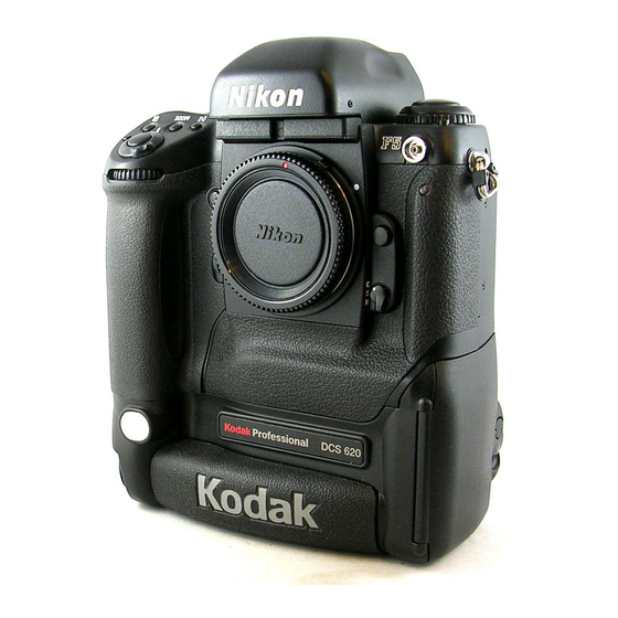
Thank you for purchasing your new KODAK PROFESSIONAL DCS 600 Series Camera (DCS 620, 620x, 660, or 660M). This portable camera system, which combines technologies of Eastman Kodak Company and Nikon Corporation, will allow you to take and store high-resolution, high-quality digital images. Before you start using the camera, you should follow the instructions listed below. -
Page 20: System Requirements For Your Computer
The following sections list the required and optional computer hardware and software needed to run the DCS Host Software with Adobe Photoshop on the Macintosh, and TWAIN-compliant applications on the PC. Refer to the KODAK PROFESSIONAL DCS Host Software User’s Manual on the DCS Host Software CD included with your camera. -
Page 21: Warnings
AC adapter and/or the camera. Use only the AC adapter (either included with your camera or available from Kodak as an accessory). Do not plug other adapters into the camera. The AC adapter is for indoor use only. Do not use the supplied AC adapter for any purpose other than for the DCS 600 Series camera. -
Page 22: Important Safeguards And Precautions
Important Safeguards and Precautions The exclamation point in an equilateral triangle is intended to alert the user to the presence of important operating and maintenance (servicing) instructions in the literature accompanying your camera. Read Instructions—Read all the safety and operating instructions before operating your camera. - Page 23 Object or Liquid Entry—Never push foreign objects of any kind into your camera openings. The objects could touch dangerous voltage points or short out parts and cause a fire or electric shock. Never spill liquid of any kind on your camera.
- Page 24 Humidity, Condensation—We recommend operating your camera within the range of 8% to 85% relative humidity, non-condensing. If condensation occurs, added time may be required to read from or write to a PC Card. Condensation may be present if the camera system and/or PC Cards are moved from a relatively cold environment (like an air conditioned hotel room), into a warm, humid environment.
-
Page 25: Electromagnetic Emissions
Electromagnetic Emissions This equipment has been tested and found to comply with the limits for a Class B digital device, pursuant to Part 15 of the FCC Rules. These limits are designed to provide reasonable protection against harmful interference in a residential installation. This equipment generates, uses and can radiate radio energy and, if not installed and used in accordance with the instructions, may cause harmful interference to radio communications. -
Page 26: About Your Camera
About Your Camera HERE Your DCS 600 Series camera (an integration of Nikon and Kodak technologies) provides a rich set of features that allow you to capture images of the highest quality. The camera has been designed and built to meet the needs of demanding professionals, for sports, photojournalism, scientific, industrial, forensic and nearly every other professional use of photography, as well as high-quality personal photography. - Page 27 DCS Host software included on the DCS Host Software CD. (Refer to the KODAK PROFESSIONAL DCS Host Software User’s manual, on the CD.) You can then use the images in other applications or edit them with your image...
-
Page 28: Nomenclature
Nomenclature Camera Front AF Area Mode button Exposure Mode (MODE) button Camera strap eyelet Exposure Compensation button Shutter Release button Sub-Command dial Depth-of-field Preview button Mirror Lockup lever White Balance sensor * Vertical Shutter release * With firmware version 3.09, or higher, white balance is accomplished using image data rather than the White Balance sensor. -
Page 29: Camera Back
Camera Back Eyepiece Shutter lever Finder Release button Alert LED Image LCD panel Display button Selector button Record/Tag button White Balance button Back Status LCD panel button Auto Exposure/ Flash Exposure Bracketing button Shutter Speed/Aperture/ Focus Area Lock button Label Viewfinder eyepiece Auto Exposure/ Autofocus Lock button... -
Page 30: Camera Top
Camera Top Metering System selector lock release Metering System selector Drive Mode selector lock release Drive Mode/Self Timer selector Accessory Shoe Camera Bottom AF Area Mode button Power/LCD Panel Illumination switch Shutter Release button Power Switch lock release Exposure Compensation button Exposure Mode (MODE) button... -
Page 31: Camera Sides
Camera Sides IEEE 1394 cable port (cover not shown) AC Adapter connection (cover not shown) Battery/PC Card door Battery/PC Card door latch Vertical shutter release lock Vertical Shutter release Camera strap eyelet... -
Page 32: Open Battery/Pc Card Door
Open Battery/PC Card Door Battery Card Busy LED Serial port PC Card Eject button... -
Page 33: Viewfinder
Viewfinder 1. Focus area indicators 2. Exposure level (for waist-level finder DW-30 or 6x high-magnification finder DW-3i in manual exposure) 3. Reference circle for Center-weighted metering 4. Focus brackets/Spot metering 5. Green Ready light 6. Focus indicators: • indicates a subject is in focus;... -
Page 34: Navigate Switch
Navigate Switch The Navigate switch is a four-way rocker switch located on the back of the camera. It is accessible whether you are holding the camera horizontally or vertically. Display button Selector button Record/Tag button White Balance button Using the Navigate switch to Navigate the Image LCD Panel The Navigate switch operates in the following manner when you use it with the Display or Selector buttons (described on the next page): Navigate through images displayed on the Image LCD panel by pressing and... -
Page 35: Digital Function Buttons
Digital Function Buttons There are four buttons associated with your camera’s digital functions. You can access the digital functions when you use these buttons in conjunction with the Navigate switch. Display Button Press and release the button to turn the Image LCD panel On or Off. Press and hold the button and use the Navigate switch to scroll across the menu bar icons. -
Page 36: Lcd Panels
LCD Panels SLOW REAR CUSTOM AUTO Top Status LCD Panel Shutter speed lock Shutter speed Auto Exposure/Flash Exposure bracketing Exposure mode Flexible program Exposure compensation Exposure compensation value Top Status LCD panel Image LCD panel Back Status LCD panel Aperture lock LOCK LOCK Aperture... -
Page 37: Back Status Lcd Panel
Back Status LCD Panel ISO/Bracketing information/ Custom Setting ISO Setting mode Bracketing bar graphs Auto Exposure/Flash Exposure Bracketing AUTO White Balance Frame number Frames remaining on PC Card Image LCD Panel The Image LCD panel has been designed for ease of use with maximized space for menu choices and image-related information. - Page 38 When you select a Menu bar icon, the following screens appear: Icon Folder icon Displays the Folder dropdown menu. Menu icon Displays a dropdown menu with choices for the Main, Properties, and Custom Settings menus. Display icon Displays a dropdown menu with choices for Single, Four, and Nine Image Review...
-
Page 39: Navigation Techniques
Navigation Techniques Use the following guidelines when navigating the Image LCD panel 2-14 To Display the Menu bar and select a Menu bar icon: Press and hold the Display button and use the Navigate switch until the desired icon is highlighted. To Display a Dropdown menu: Highlight the Folder, Menu, or Display icon, and continue pressing... - Page 40 To Choose an item from a dropdown menu: Continue to press the Display button and use the Navigate switch until the desired menu choice is highlighted. To Choose an item from a menu screen: Press and hold the Selector button and use the Navigate switch to highlight your choice.
-
Page 41: Status Bar
Status Bar A Status bar appears whenever images are displayed (Single, Four, or Nine Image Review mode). Information about the currently selected image appears on the Status bar: Two PC Cards One PC Card 2-16 The currently active PC Card (if there are two cards in the camera) The currently active folder Sound icon (if one or more sound... -
Page 42: Command Dials
Command Dials Your camera’s Main-Command dial and Sub-Command dial can be used alone or in combination with other buttons to select various functions or modes. Main-Command Dial Use the Main-Command dial by itself or with various buttons to perform the following: Rotating the Main-Command Dial by Itself AE-L AF-L... -
Page 43: Rotating The Main-Command Dial While Pressing Buttons
Rotating the Main-Command Dial While Pressing Buttons Select Exposure mode. Refer to “Exposure Mode” on page 8-14. Perform Exposure Compensation. Refer to “Exposure Compensation” on page 13-19. Select AF area mode. Refer to the “Selecting AF Area Mode” section on page 9-4. Select ISO. -
Page 44: Sub-Command-Dial
Sub-Command-Dial Use the Sub-Command dial by itself or with various buttons to perform the following: Rotating the Sub-Command Dial by itself Rotating the Sub-Command Dial While Pressing Buttons: Select the aperture in Aperture- Priority Auto or Manual exposure mode. Refer to “Aperture-Priority Auto Exposure Mode”... -
Page 45: Drive Mode/Self-Timer Selector
Drive Mode/Self-Timer Selector This dual-purpose control allows you to select a Drive mode or set the self timer. When you select a Drive mode, you specify whether one or more images will be captured when you depress the Shutter Release button. 2-20 To set a Drive mode: Press the lock release for the Drive... -
Page 46: Lens
Lens Refer to Appendix C for a list of lenses that are compatible with your camera. CAUTION: Only use lenses that are listed in Appendix C. Other lenses can potentially break your camera’s anti-aliasing or IR filter. Refer to “Anti-aliasing filter” on page 2- Mounting the Lens Remove the camera body cap and the front and rear lens caps. -
Page 47: Setting The Lens To The Minimum Aperture
Setting the Lens to the Minimum Aperture For Programmed Auto or Shutter-Priority Auto mode, use the minimum aperture lock lever to lock the lens aperture at f/16. 2-22 Position the lens in the camera’s bayonet mount so that the mounting indexes on the lens and camera body are aligned. - Page 48 Set the lens to its minimum aperture (f/16). Slide the lock lever in the direction of the aperture ring so that the white dot on the tab aligns with the orange dot. Slide the lock lever in the opposite direction to release the lock.
-
Page 49: Removing The Lens
Removing the Lens 2-24 Press and hold the Lens Release button and turn the lens clockwise. If you don’t plan to mount a lens for a while, attach the supplied BF-1A body cap. (The BF-1 body cap cannot be used on your camera.) -
Page 50: Imager
Imager The imager records light when you capture an image. The imager size and ISO varies, depending on your camera model. Camera DCS 620 2 million pixels DCS 620x 2 million pixels DCS 660 6 million pixels DCS 660M 6 million pixels Anti-aliasing filter The DCS 620, DCS 620x, and DCS 660 cameras each contain an anti-aliasing filter which improves overall image quality and helps reduce aliasing at certain focal distances. -
Page 51: Viewfinder Diopter
Viewfinder Diopter You can compensate for near- or far-sightedness and see more clearly through the viewfinder by adjusting the finder diopter within a continuous range of from –3 to +1. 2-26 Pull the Diopter Adjustment knob and rotate it in either direction until the focused image in the viewfinder’s reference circle appears sharp... -
Page 52: Illumination Switch
Illumination Switch You can illuminate the Top and Back Status LCD panels for easy viewing at night or in low light situations. Rotate the LCD Panel Illumination switch toward the to illuminate the Top and Back Status LCD panels. The LCD panel illumination switch automatically returns to the on position, and the LCD panels remain illuminated as long as the... -
Page 53: Mirror Lockup Lever
Mirror Lockup Lever When using super-telephoto lenses or performing photomicrography, it is necessary to reduce camera vibration to the absolute minimum. CAUTION: Do not to leave the camera in direct sunlight when the reflex mirror is locked in the up position. The sunlight may damage the shutter curtain. 2-28 Lock the reflex viewing mirror in the up position by rotating the... -
Page 54: Depth-Of-Field Preview Button
Depth-of-Field Preview Button The depth of field is the zone of acceptable focus in front of and behind the subject. You can preview this zone using the Depth-of-Field Preview button. The Depth-of-Field Preview button will not work properly if there is no PC Card inserted. In Aperture-Priority Auto or Manual Exposure mode, press the Depth-of-field Preview button to... -
Page 55: Accessory Shoe
Accessory Shoe Sync Terminal 2-30 Located at the top of the Multi- Meter Finder, the ISO-type hot shoe allows direct mounting of a wide range of Nikon-dedicated electronic Speedlights. Refer to “Attaching the SB-28D or SB-28DX” on page 11- CAUTION: Do not use speedlights from other manufacturers since higher voltages and/or extra... -
Page 56: Self-Diagnostic Shutter System
Self-Diagnostic Shutter System Your camera is equipped with a self- diagnostic shutter that automatically controls the shutter speed for each release of the shutter. The self-diagnostic shutter automatically detects inaccuracies in performance and readjusts the shutter speed accuracy for subsequent image capture. If a malfunction occurs or the shutter curtain fails to operate, the alert LED blinks and... -
Page 57: Changing Viewfinders
Changing Viewfinders A modified DP-30 viewfinder is included with the DCS 620 and 620x cameras. (A standard DP-30 viewfinder is included with the DCS 660 and 660M cameras.) See Appendix C for a list of compatible viewfinders. Using other viewfinders with your camera can decrease the “active area”... -
Page 58: Attaching The Finder
Attaching the Finder Slide the finder in until it clicks in place. Be sure that the Finder Release button has returned to its original position. IMPORTANT: Be sure the viewfinder is attached when you are capturing images. If the shutter is released without a viewfinder attached, stray light may enter through the focusing screen. -
Page 59: Changing Focusing Screens
Changing Focusing Screens 2-34 Turn off the camera and remove the finder. Refer to “Removing the Finder” on page 2-32. Insert your fingernail under the rear edge of the focusing screen and lift the screen out. To install a focusing screen, insert the front edge under the central ridge, then push the rear edge down into place. -
Page 60: Camera Straps
Camera Straps A neck strap and a hand strap are included with your camera. You can attach either or both. Attaching the Neck Strap Thread the ends of the neck strap through the strap fixtures. Pull firmly on the strap to make sure it is held securely by the buckles. -
Page 61: Attaching The Hand Strap
Attaching the Hand Strap 2-36 Thread the strap through both loops in the hand strap pad. Place the three-holed buckle on the strap and thread through the camera’s top strap fixture. Thread the other end of the strap through the camera’s bottom strap fixture. -
Page 62: Name Plate
Name Plate Using the DCS Acquire Module or DCS TWAIN Data Source, you can enter text that appears in certain screens on your camera. The Name Plate is useful for personalizing your camera, for example, “This camera belongs to Joe Smith”. In the DCS Acquire Module or DCS TWAIN Data Source: Click the Camera Control button. -
Page 63: Powering Your Camera
These items are included with most cameras (except base camera kit). They are also available from Kodak as accessories. The power cords allow you to use the AC adapter and the battery charger in Australia, Great Britain, Germany, Japan, and the United States. -
Page 64: Batteries
Batteries Your camera can use either NiMH (nickel metal hydride) or NiCd batteries. Extended camera metering, autofocus, or extensive LCD panel operation reduces the number of images available from a full battery charge. With a fully charged battery, the camera can provide up to the following number of images: Camera DCS 620 and 620x... -
Page 65: Inserting/Removing Batteries
Inserting/Removing Batteries You must charge a battery before using it for the first time. SLOW REAR CUSTOM AUTO Check that the Card Present icon on the Back Status LCD panel is not blinking. IMPORTANT: If the Card Present icon or the Card Busy LED inside the Battery/PC Card door are blinking, wait until the blinking... - Page 66 Lift the latch assembly on the Battery/PC Card door and turn it counter-clockwise to open the door. IMPORTANT: Be sure that the Card Busy LED is Off before you continue.
- Page 67 The white arrow opposite the connector should be pointing upwards as the battery is inserted. Some (not all) cameras have a white arrow pointing downwards (towards the camera bottom) just above the battery compartment. If your battery and your camera both have the arrows, then the arrows should be aligned as you insert the battery into the camera.
-
Page 68: Checking Battery Status
Checking Battery Status You can determine whether a battery needs charging by viewing the Battery icon on your camera’s Back Status LCD panel. (If the camera is using an AC adapter, the Battery icon is not displayed.) SLOW REAR CUSTOM AUTO Full Insufficient... -
Page 69: Battery Charger
Battery Charger You need to charge a battery before using it for the first time and whenever it is low. If you plan to use your camera without the AC adapter for an extended period of time, it is a good idea to charge one or more batteries before you begin. -
Page 70: Charging Batteries
Charging Batteries Remove the battery from the camera (page 3-3). Plug the cable from the AC adapter for charger into the battery charger jack. Select the international power cord that is appropriate for your area. Insert the appropriate end of the international power cord into the receptacle on the rear of the AC adapter for charger. - Page 71 SLOW REAR CUSTOM AUTO If your battery charger does not function as expected, check the following: The wall adapter is properly connected. There are no foreign objects lodged in the pockets. The batteries are inserted so that they properly mate with the connector in the bottom of the pocket.
-
Page 72: Conditioning (Discharging Batteries)
Conditioning (Discharging Batteries) You may occasionally need to condition a battery. You would only do so if a battery provides a noticeably shorter run time (less than 50% of normal capacity). IMPORTANT: Don’t condition your batteries too often or they will wear out prematurely. You can condition a battery in one slot while charging a battery in the other. -
Page 73: Battery Conservation
Battery Conservation Your camera has several built-in functions that minimize drain on your battery. PowerSave Mode If your camera is powered by an AC adapter or is connected to a computer with IEEE 1394 cable, it will not enter PowerSave mode. If you don’t use your camera for 30 minutes, it will enter PowerSave mode (go to sleep). -
Page 74: Image Lcd Panel Timeout
Image LCD Panel Timeout The Image LCD panel will turn off if you have not used the camera for 60 seconds. You can change the setting for Image LCD timeout. Refer to “Setting Display Off Time” on page 4-3. Meter Timeout Your camera’s meter remains on for 8 seconds after you lightly press the Shutter Release button. -
Page 75: Ac Adapter For Camera
A line voltage outside of this range can destroy the AC adapter and/or the camera. Tips Use only the KODAK AC adapter; do not plug other chargers or adapters into the camera. The AC adapter is for indoor use only. -
Page 76: Connecting The Ac Adapter For Camera
Connecting the AC Adapter for Camera 3-14 Open the connector cover at the side of the camera. Plug the AC adapter for camera into the AC Adapter connection. Select the international power cord that is appropriate for your area. - Page 77 Plug the appropriate end of the power cord into the AC adapter for camera. Plug the power cord into a wall outlet. You can connect or disconnect the AC adapter while a battery is in the camera. The AC adapter for camera will charge a battery in the camera.
-
Page 78: Configuring Your Camera
INSERT PHOTO Configuring Your HERE Camera This section describes how to change various camera settings. Date and Time You can set the date and time. The format for the date is year/month/day, and the format for time is hour:minute:second based on a twenty-four-hour clock. The setting is maintained when you turn off the camera, after PowerSave, or when you remove the battery for a few days. - Page 79 The Date/Time screen appears. There are six fields: year, month, day, and hour, minutes, seconds. Press and hold the Selector button and press the left or right side of the Navigate switch to highlight the desired field. Press and hold the Selector button and press the top or bottom of the Navigate switch to change the highlighted field.
-
Page 80: Camera Properties
Camera Properties You can set the following camera properties using camera controls: Display Off time, Powersave time, Resolution, Enable Sharpening, Use FOLDER01,and Total Actuations. The list of properties may change as new versions of firmware become available. The wording in the screens may not be exactly as shown. Setting Display Off Time You can change the Display Off time (the length of time before the Image LCD panel turns off). -
Page 81: Enabling Sharpening
Enabling Sharpening DCS 620, 620x, and 660 cameras are equipped with an antialiasing filter, an optical filter that is mounted inside the camera in front of the electronic imager. This filter eliminates unwanted color artifacts, and improves overall image quality at the expense of a small loss of sharpness. -
Page 82: Setting File Resolution
Setting File Resolution You can specify a file resolution to be saved in the header of subsequently captured images. This property does not affect image processing in the camera, the DCS Acquire Module, or the DCS TWAIN Data Source. The specified resolution is used by applications such as Photoshop when displaying the images. -
Page 83: Determining Total Actuations
Determining Total Actuations You can determine the number of images captured by your camera from the time of its manufacture. Use Folder 1 You can specify whether the default place to store images is an empty folder or folder 1 when you insert a new PC Card. -
Page 84: Custom Settings
Custom Settings You can set Custom Settings using the Custom Settings menu (described below) or the button (page 4-7). In general, the method described below is easier to use, since the settings are labeled. Select the Menu icon, then choose Custom Settings from the dropdown menu. -
Page 85: Using A Pc Card
INSERT PHOTO Using a PC Card HERE As you capture images, they are stored on a PC Card (PCMCIA card). Before capturing images, you may want to make a few preparations so that the images will be stored according to your needs. This chapter describes the use of the PC Card and provides instructions for storing images. -
Page 86: Dual Slots For Pc Cards
Dual Slots for PC Cards Your camera has two PC Card slots. With Type II PC Cards, you can use one or both slots. With Type III PC Cards, only one slot can be used. The card in the slot closest to the camera back is referred to as CARD0, and the card in the slot closest to the camera front is referred to as CARD1. -
Page 87: Inserting/Removing Pc Cards
Inserting/Removing PC Cards It is not necessary to turn off the camera before inserting or removing a card. SLOW REAR CUSTOM AUTO Check the Card Present icon on the Back Status LCD panel. It blinks when a card is busy. IMPORTANT: If the Card Present icon is blinking, wait until it stops... - Page 88 IMPORTANT: Be sure that the Card Busy LED is Off before continuing. To insert a PC Card: slide it all of the way into the card slot and press firmly. A label inside the door indicates the proper position for the card.
- Page 89 SLOW REAR CUSTOM AUTO To remove a PC Card, press the Eject button and pull the card out. Close the Battery/PC Card door. The Card Present icon is displayed on the Back Status LCD panel when there is a PC Card in the camera.
-
Page 90: Formatting A Pc Card
Formatting a PC Card To prevent formatting the wrong PC Card, there can only be one card in the camera when you format a card. Format the card using either the quick format or the full format feature. IMPORTANT: Quick format, while faster, is not recommended if there is a possibility that there are defects on the PC Card. - Page 91 If you remove the active card, the message at the left appears. Re-insert the card in the proper slot, then select Retry. A confirmation screen appears. Select Yes or No. If you choose No, the Main menu appears and the card is not formatted.
-
Page 92: Selecting A Pc Card Or Folder
Selecting a PC Card or Folder Images are stored in folders on a PC Card. There is always at least one empty folder on your PC Card. When you store an image in an empty folder, a new empty folder is automatically created. -
Page 93: Saving Files
Saving Files JPEG and TIFF File Processing The DCS 620 and 620x cameras support background image processing that produces JPEG or TIFF RGB files that can be opened directly by any image editing software. This feature is not available on the DCS 660 or 660M cameras. The choices for processed files are JPEG Good, Better, Best, and TIFF RGB. -
Page 94: Processing Images
Processing Images Select the Menu icon, then choose Main Menu from the dropdown menu. Refer to “Navigation Techniques” on page 2-14. Select Processing from the Main menu. The Processing menu appears. If two PC Cards are inserted, the active card is indicated (for example, All on CARD1). - Page 95 When you enable processing, certain conditions may exist which will cause other screens to appear, as shown in the table below. Condition There is no PC Card in the camera. Processing is enabled for the selected folder and there are no images in the folder.
- Page 96 Condition Your processing settings are set to delete the original TIFF image when you process files. Refer to “Changing Processing Settings” on page 6-5. The active PC Card becomes full as images are being processed. This can occur regardless of whether there are one or two cards in the camera.
-
Page 97: Changing Processing Settings
Changing Processing Settings There are several processing settings that you can change. The settings are applied to images as they are processed. Processing Screen Settings Original TIFF File Type Resolution Select Change Settings from the Processing menu. The Processing Settings menu appears with the current values shown in parentheses. - Page 98 Processing Screen Settings Noise Reduction Look Sharpening Level * Exposure * The Sharpening Level setting in the Processing menu determines whether sharpening is applied when images are processed on the camera. The Sharpening property in the Properties menu determines whether sharpening is applied by the DCS Host software. Refer to “Enabling Sharpening”...
-
Page 99: Working With Tiff Custom Files On Your Computer
DCS File Format Module. If the CD includes a version prior to 5.8, the DCS File Format Module is not included. To download the DCS File Format Module, visit the Kodak Web site (www.Kodak.com). If you attempt to open TIFF Custom files in Photoshop without using the DCS File Format Module, the DCS Acquire Module, or DCS TWAIN Data Source, only the thumbnail version is available, yielding a less than optimal image resolution. -
Page 100: Iptc Data Management
Acquire Module or DCS TWAIN Data Source (version 5.8 or later) and save it to a PC Card. (Refer to the KODAK PROFESSIONAL DCS Host Software User’s Manual.) Once IPTC data has been saved to a PC Card, you can load the data into your camera (page 6-9). -
Page 101: Loading Iptc Data From A Pc Card
Loading IPTC Data from a PC Card With the Load IPTC Data screen displayed (page 6-8), choose Load from Card. The Load IPTC Data screen appears with a list of the IPTC files on the active PC Card. (If only one card is in the camera, the card choices do not appear.) Press and hold the Selector button and use the Navigate... -
Page 102: Quick Start
INSERT PHOTO Quick Start HERE This chapter contains information that enables you to start using your camera. Much of the information in this chapter can be found in greater detail in other areas of the manual. Before You Start If you have not already done so, charge your battery using the external battery charger that was included with your camera. - Page 103 Insert the battery into the battery slot. Insert a PC Card into the card slot.
- Page 104 Turn the latch assembly clockwise to close the Battery/PC Card door. Remove the camera body cap and the front and rear lens caps.
- Page 105 Position the lens in the camera’s bayonet mount so that the mounting indexes on the lens and camera body are aligned. Taking care not to press the Lens Release button, twist the lens counter clockwise until it locks in place. Press the Power Switch Lock release.
-
Page 106: The Ac Adapter For Camera
The AC Adapter for Camera Conserve your battery and power your camera by using the AC adapter for camera, whenever possible. Refer to “AC Adapter for Camera” on page 3-13. Connecting the AC Adapter for Camera Open the connector cover at the side of the camera. - Page 107 Select the power cord with universal plug that is appropriate for your area. Plug the appropriate end of the power cord into the AC adapter for camera. Plug the power cord into a wall outlet.
-
Page 108: Optional Settings Before You Start
Optional Settings Before You Start Set the Date and Time Select a PC Card or Folder Before capturing images, you should specify a PC Card and folder for storing images. Refer to “Selecting a PC Card or Folder” on page 5-8. Select the Menu icon, then choose Main Menu from the dropdown menu (page 2-14). -
Page 109: Basic Shooting
Basic Shooting Set the lens aperture to its minimum position as described in the “Setting the Lens to the Minimum Aperture” section on page 2-22. Set the Drive mode selector to S for Single-frame shooting. Set the Focus mode selector to S for Single Servo AF. - Page 110 Press and hold the AF Area Mode button and rotate the Main-Command dial to select Single Area AF mode. AE-L AF-L AF-ON The selected focus area of the Top Status LCD panel displays only [ ]. The Focus bracket also appears in the viewfinder.
- Page 111 P appears in the Top Status LCD panel and viewfinder. Press the Navigate switch to position the focus brackets on your main subject. 7-10...
- Page 112 Lightly press the Shutter Release button. If HI appears in the shutter speed position—Over- exposure alert: Use a NIKON ND filter. If Lo appears in the shutter speed position—Under- exposure alert: Use an accessory NIKON Speedlight. 7-11...
- Page 113 CAUTION: Always remove batteries before storing your camera to prevent damage due to leaking batteries. 7-12 Confirm that a green “•” appears inside the viewfinder (indicating successful focusing), then fully depress the Shutter Release button to capture the image. The Shutter cannot be released in the following situations: When blinks: Focus...
-
Page 114: Reviewing Images On Your Camera
Reviewing Images on Your Camera You can display one, four or nine images on the Image LCD panel. Single Image Review mode Four Image Review mode Nine Image Review mode Select the Display icon, then choose Single, Four, or Nine Image Review mode from the dropdown menu (page 2-14). -
Page 115: Setting Display Contrast
Setting Display Contrast You can change the contrast to lighten or darken the images displayed on the Image LCD panel. 7-14 Select the Contrast icon. Refer to “Menu Bar” on page 2-12. A grayscale bar is displayed at the side of the image and a slider is displayed across the top. -
Page 116: Setting Display Options
Setting Display Options You can view areas of overexposure, an exposure histogram, and information about the selected image. Select the Menu icon, then choose Main Menu from the dropdown menu. Refer to “Navigation Techniques” on page 2-14. Select Display Options from the Main menu. - Page 117 Image name Date Time Shutter speed ISO setting Aperture Exposure mode Exposure compensation 7-16 If you turn the Histogram/Info option on while in single image review mode, the Histogram and exposure info will appear. The information will not be displayed In Four or Nine Image Review mode.
-
Page 118: Tagging Images
DCS Host software where you can select tagged or untagged images and perform a variety of operations. Refer to the KODAK PROFESSIONAL DCS Host Software User’s Manual on the DCS Host Software CD included with your camera. -
Page 119: Deleting Images
Deleting Images You can delete one or more images from a PC Card in your camera. When you do so, any associated sound files are also deleted. Refer to “Associating a Sound File with an Image” on page 7-20. Deleting a Single Image 7-18 Press and hold the Display button and the Selector button at... -
Page 120: Deleting More Than One Image
Deleting More Than One Image You can delete all images on the PC Card, all images in a folder, all untagged images on the PC Card, or all untagged images in a folder. To delete untagged images (described below), tag any images that you want to DO NOT... -
Page 121: Associating A Sound File With An Image
You can record sound files for your images, then play back the sound files using the DCS Host software (if your computer has a sound board). Refer to the KODAK PROFESSIONAL DCS Host Software User’s Manual on the DCS Host Software CD included with your camera. - Page 122 You cannot record sounds and the Microphone icon is not displayed in the Back Status LCD panel under the following circumstances: No image is in the current folder No PC Card is in the camera The PC Card in the camera is full You are capturing an image Speak into the microphone while continuing to press and...
-
Page 124: Controlling Exposure
INSERT PHOTO Controlling HERE Exposure This chapter describes the functions available for controlling exposure in your camera. White Balance The DCS 620, 620x, and 660 cameras offer Custom White Balance functionality. (This feature is not available with the DCS 660M camera.) You can save White Balance settings using the your camera or the DCS Acquire Module or DCS TWAIN Data Source (version 5.8 or later). - Page 125 SLOW REAR CUSTOM AUTO AUTO Auto - Flash Flourescent Daylight Tungsten Flash Custom The table below shows the predicted color temperature at each White Balance setting: White Balance Setting Daylight Tungsten Fluorescent On-Camera Flash To determine the current white balance setting, check the White Balance icons on the Back LCD panel.
-
Page 126: Selecting Custom White Balance
Selecting Custom White Balance You must select Custom White Balance before selecting, deleting, or loading Custom White Balance settings. SLOW REAR CUSTOM AUTO SLOW REAR CUSTOM AUTO Press and hold the White Balance button and use the Navigate switch until no White Balance icons appear in the Back LCD panel. -
Page 127: Using White Balance Settings
Using White Balance Settings Once you have selected Custom White Balance, you can access several Custom White Balance functions. Press the White Balance button. If the Image Display was Off, it turns On. If there are no images in the folder, this screen appears. - Page 128 Options—The White Balance Settings menu appears. You can: Select a White Balance setting from those loaded on the camera (page 8-6) Delete a White Balance setting from the camera (page 8-6) Load a White Balance setting from a PC Card to the camera (page 8-7) Save a White Balance setting (page 8-9)
-
Page 129: Selecting White Balance Settings
Selecting White Balance Settings With the White Balance Settings menu displayed (page 8-4), choose one of the following: Image #xxxx: The White Balance values from the selected image are applied to images that you capture. Previously loaded setting—The White Balance values from the previously loaded setting (page 8-7) are applied to images that you capture. -
Page 130: Loading White Balance Settings
Loading White Balance Settings You can load White Balance settings from a PC Card into your camera. (The settings are saved to the card using the DCS Host software. There are a few rules to remember when you load White Balance settings. If you should forget any of the rules, an appropriate error message appears, as shown in the table below. - Page 131 With the White Balance Setting screen displayed (page 8-4), choose Load from Card. The Load White Balance Setting screen appears with a list of the White Balance settings on the active PC Card. (If only one card is in the camera, the card choices do not appear.) Select the desired card.
-
Page 132: Saving White Balance Settings Using Your Camera
Capture an image with a neutral area (such as a gray or white card) in the center. Using the DCS Acquire Module or DCS TWAIN Data Source, save the White Balance setting to a PC Card. (Refer to the KODAK PROFESSIONAL DCS Host Software User’s Manual.) When you save a White Balance setting to a PC Card, a “.wb”... -
Page 133: Exposure Metering System
Exposure Metering System Your camera has three types of exposure metering systems: 3D Color Matrix Metering Center-Weighted Metering (page 8-11) Spot Metering (page 8-12) 3D Color Matrix Metering With D-type AF Nikkor lenses (including AF-I or AF-S Nikkor), 3D Color Matrix metering is automatically activated. -
Page 134: Center-Weighted Metering
Center-Weighted Metering With approximately 75% of the meter’s sensitivity concentrated on the 12 mm diameter circle within the viewfinder and 25% outside this circle, the meter becomes useful in situations where you want to base exposure on a specific area in the scene. To measure the brightness of the picture’s off-center portion in auto exposure mode, use the camera’s AE-L/AF-L button. -
Page 135: Spot Metering
Spot Metering Nearly 100% of the meter’s sensitivity is concentrated in a 4 mm diameter area (approximately1.5% of the entire frame) within the selected focus area of the viewfinder. (With focusing screens other than EC-B-type, the sensitivity is concentrated in a 6mm diameter area or approximately 3.3% of entire frame.) Use this meter for highly selective exposure control. -
Page 136: Setting The Metering System
Setting the Metering System The appropriate symbol appears in the viewfinder. 3D Color Matrix Metering Center-Weighted Metering Rotate the Metering System Selector while pressing the Metering System Selector Lock Release to select the desired type of exposure metering. Spot Metering 8-13... -
Page 137: Exposure Mode
Exposure Mode Light reaching the imager is controlled by the shutter speed and lens aperture. The proper combination results in a correct exposure. Shutter speed and lens aperture settings are based on the ISO speed and the operation of the camera’s exposure control system. The relationship between aperture and shutter speed is described in the following example: A shutter speed of 1/500 second admits half the light of a shutter speed of 1/250... -
Page 138: Shutter-Priority Auto Exposure Mode
Shutter-Priority Auto Exposure Mode This mode allows you to manually set your desired shutter speed. To freeze the action, use a high shutter speed; to create motion effects, choose a slower shutter speed. Your camera automatically selects the proper aperture to match the manually set shutter speed ensuring a correct exposure. -
Page 139: Manual Exposure Mode
Manual Exposure Mode The Manual exposure control allows you to change both aperture and shutter speed settings. For a technically correct exposure, follow the recommendation of the camera’s light meter, as indicated in the viewfinder. To achieve a specific creative effect (for example, intentional blur, intentional under- or over-exposure), disregard the LCD and modify the recommended exposure settings. -
Page 140: Setting Exposure Mode
Setting Exposure Mode AE-L AF-L AF-ON Programmed Auto Shutter-Priority Auto Aperture-Priority Auto Manual Rotate the Main-Command dial while pressing the MODE button. The exposure mode changes as in the sequence shown at the left: If you use lenses that don’t have a CPU, or accessories such as a bellows attachment or extension rings:... -
Page 142: Focusing
INSERT PHOTO Focusing HERE This chapter discusses focus area, Focus mode, special focusing situations, and the effect of the antialiasing filter on focus. It also discusses sharpening in the DCS 660 camera. Focus Area Five focus areas are available with your camera. Selecting the Focus Area To select the desired focus area, press the top, bottom, left or right of... - Page 143 Corresponding focus areas appear in the Top Status LCD panel and the viewfinder. Arrows on top and to the right of the viewfinder also indicate the selected focus area. Focus Area Center Left Right Bottom When Spot Metering is selected, shifting the focus area also shifts the Spot Metering area accordingly.
-
Page 144: Locking The Focus Area
Locking the Focus Area You can lock the focus area using the lock function. Select the desired focus area, then press the Navigate switch to any position while pressing (Focus area lock) button. appears above the focus LOCK area icon in the Top Status LCD panel To release the lock, press the Navigate switch while pressing... -
Page 145: Selecting Af Area Mode
Selecting AF Area Mode Single Area AF Press and hold the AF area mode button and rotate the Main- Command dial to select Single Area AF or Dynamic AF mode. Single Area AF mode and AE-L AF-L AF-ON Dynamic AF mode are described on the following pages. - Page 146 Dynamic AF When Dynamic AF mode is selected, a appears in the selected focus area, + appears in all five focus areas of the Top Status LCD panel, and all five AF sensors are active. The example at the left shows center focus area selection.
-
Page 147: Focus Mode
Focus Mode Your camera has two focus modes: autofocus and manual. Autofocus There are two default Autofocus modes: Single Servo AF with Focus-Priority Continuous Servo AF with Release-Priority In either of these modes—and in any Drive mode—focus tracking is automatically activated when the subject starts moving. - Page 148 Single Servo AF with Focus-Priority (Stationary Subject) Set the Drive Mode selector to S (Single Servo AF). Lightly press the Shutter Release button to activate autofocus. Confirm that a green • appears in the viewfinder, then fully depress the Shutter Release button.
-
Page 149: Single Servo Af With Focus-Priority (Moving Subject)
Single Servo AF with Focus-Priority (Moving Subject) Single Servo AF is convenient for off-center subjects. Refer to “Focus Lock For Off- center Subjects” on page 13-14. Perform steps 1 - 3 as for a stationary subject (page 9-7). Confirm that a green • appears in the viewfinder, then fully depress the Shutter Release button. -
Page 150: Continuous Servo Af With Release-Priority
After capturing images with the Drive mode set to S, you do not have to remove your finger from the Shutter Release button to capture the next image. Slightly release pressure on the button so it is only half-depressed, then fully depress it to release the shutter again. -
Page 151: Manual Focus
If a appears in the viewfinder, the lens is focused behind the subject. If a appears in the viewfinder, the lens is focused in front of the subject. If a blinks in the viewfinder, autofocus is not possible. Refer to “Special Focusing Situations in AF”... -
Page 152: Manual Focus With The Electronic Rangefinder
Manual Focus with the Electronic Rangefinder The Electronic Rangefinder provides you with viewfinder indications that show the focus status while you are focusing. It works with most Nikon lenses (including AF Nikkor when operated manually) having a maximum aperture of f/5.6 or faster. (For a complete list of usable lenses, refer to the Lens Compatibility chart in Appendix C). - Page 153 9-12 While lightly pressing the Shutter Release button, rotate the lens focusing ring in the direction indicated by the focus- to-left arrow or focus-to-right arrow , until the arrow disappears and the in-focus indicator • appears. If the focus-to-left arrow not disappear when you turn the focus ring counterclockwise to its limit, the subject is too close...
-
Page 154: Manual Focus Using A Clear Matte Field
Manual Focus Using a Clear Matte Field Special Focusing Situations in AF Autofocus operation depends on general lighting, subject contrast and detail, and other technical factors. In rare situations where autofocus (and manual focus with the Electronic Rangefinder) is not possible, blinks, telling you to focus manually with the clear matte field (described on page 9-13) or perform autofocus on another subject located at the same distance. - Page 155 9-14 Very dark subject: Focus manually with the clear matte field, or for Single Servo AF, focus on another brighter subject located at the same distance, then lock the focus and recompose. Refer to “Focus Lock For Off- center Subjects” on page 13- Low-contrast subject Focus manually with the clear matte field, or for Single Servo...
-
Page 156: Antialiasing Filter Or Ir Filter: Effect On Focus
In the following situations, ignore the in-focus indicator (•). When the subject is obscured by an object such as a fence in the foreground, use Single Area AF mode and select the subject’s focus area (described on page 9-1) or focus manually with the clear matte field. -
Page 157: Sharpening
You can set a camera property that tells the DCS Host software whether sharpening should be applied. Refer to “Enabling Sharpening” on page 4-4. For information on the Sharpening function, refer to the KODAK PROFESSIONAL DCS Host Software User’s Manual on the DCS Host Software CD included with your camera. -
Page 158: Capturing Images
INSERT PHOTO Capturing Images HERE This chapter provides an overview of the things you need to do to capture and manage images. Much of the information is described in greater detail in other parts of the manual. Preparing to Capture an Image Hold the camera properly. - Page 159 To set the meter so the Status LCD panels turn Off after 4 seconds, CUSTOM 16 seconds, or 32 seconds, use Custom Setting #15. Refer to “Custom Settings” on page 13-32. To deactivate autofocus when the Shutter Release button is lightly CUSTOM pressed, use Custom Setting #4.
-
Page 160: Basic Shooting
Basic Shooting Set the lens aperture to its minimum position. Refer to “Setting the Lens to the Minimum Aperture” on page 2- Set the Drive Mode selector to S for Single-frame shooting. Refer to “Drive Mode” on page 10-10. Set the Focus mode selector to S for Single Servo AF. - Page 161 10-4 Press and hold the AF area mode button and rotate the Main- Command dial to select Single Area AF mode. AE-L AF-L AF-ON The selected focus area of the Top Status LCD panel displays only [ ]. The Focus bracket also appears in the viewfinder.
- Page 162 P appears in the Top Status LCD panel and viewfinder. Press the Navigate switch to position the focus brackets on your main subject. Refer to “Navigate Switch” on page 2-9. Lightly press the Shutter Release button. 10-5...
- Page 163 If HI appears in the shutter speed position—Over-exposure alert: Use a NIKON ND filter. If Lo appears in the shutter speed position—Under- exposure alert: Use an accessory NIKON Speedlight. Confirm that a • appears inside the viewfinder (indicating successful focusing), then fully depress the Shutter Release button to capture the image.
- Page 164 The Shutter cannot be released in the following situations: When blinks—Focus manually. Refer to “Special Focusing Situations in AF” on page 9-13. When appears—Subject is too close. Move away from your subject. To conserve battery power, turn off the camera when you are not using it. IMPORTANT: Always remove batteries before storing your camera to prevent damage due to leaking batteries.
-
Page 165: Two-Button Reset
Two-Button Reset Pressing the buttons simultaneously for more than two seconds resets or cancels various settings. Two-Button Reset sets the following modes: Mode Exposure mode AF Area mode Focus Area Flash Sync Two-Button Reset cancels the following modes: Mode Flexible Program Exposure compensation Auto Exposure/Flash Exposure Bracketing... -
Page 166: Iso
The ISO setting controls imager sensitivity. The higher the number, the greater the sensitivity, and vice versa. ISO 400 is twice as sensitive as ISO 200, and half as sensitive as ISO 800. The following table shows the ISO range for your camera: Camera DCS 620 DCS 620x... -
Page 167: Drive Mode
Drive Mode Drive mode determines whether one or more images are captured when you are pressing the Shutter Release button. There are four automatic Drive modes: Single frame Continuous low-speed shooting Continuous high-speed shooting Continuous silent-low-speed shooting Choosing a Drive Mode 10-10 Rotate the Drive mode/Self-timer selector while pressing the Drive... -
Page 168: Single-Frame Shooting
Single-Frame Shooting With the Drive mode at S, fully pressing the Shutter Release button captures one image. To capture the next image, lift your finger from the button, then fully press it again. Use Single-frame shooting for stationary subjects or subjects that do not require several frames of rapid firing. -
Page 169: Continuous Shooting
Continuous Shooting 10-12 Images are captured continuously as long as you keep the Shutter Release button fully pressed. With the DCS 620 and 620x, you can capture up to 3.5 fps in C mode, up to 2.0 fps in C mode and approximately 1.0 fps in C mode. -
Page 170: Using The Vertical Controls
Using the Vertical Controls Your camera is designed to facilitate capturing images in a vertical orientation. Starting with the camera in the normal position for capturing images, turn it 90 degrees in a counter clockwise direction. Press the Vertical AF Start button if you plan to use autofocus. -
Page 171: Intervalometer
Intervalometer Your camera has an Intervalometer which you can set so that a sequence of images are captured automatically at specified intervals over a specified period of time. You might use the Intervalometer to capture a flower bud opening or for unattended surveillance. You can set the following: Number of frames to be captured Interval between exposures... - Page 172 Your choices on the Intervalometer screen cause the following screens to appear: Intervalometer Screen Settings Timer Count Timer Interval Timer Delay Timer Enable To change settings in these screens, use the same technique described for setting Display Off Time. Refer to “Setting Display Off Time” on page 4-3. Your Action Result Set the timer...
-
Page 173: Flash Photography
Flash Photography The NIKON Autofocus SB-28D Speedlight has been specifically designed for DCS 600 Series cameras. This Speedlight retains all functionality of the NIKON SB-28 Speedlight and adds functionality developed specifically for your camera. Most of the SB-28D functionality is described in the SB-28 instruction manual (included with your Speedlight) and you will need to refer to that manual. -
Page 174: Auto Aperture Mode
Auto Aperture Mode While a variety of flash modes are available with the SB-28D Speedlight, only Auto Aperture mode is discussed in this Chapter. (Others are discussed in the SB-28 instruction manual.) Auto Aperture mode has been developed specifically for your camera. Auto Aperture mode automatically controls flash output to achieve correct exposure for both the subject and background. -
Page 175: Attaching The Sb-28D Or Sb-28Dx
Attaching the SB-28D or SB-28DX Turning on the SB-28D or SB-28DX 0.6 0.8 STBY ZOOM ZOOM MODE FLASH ON / OFF Mount the SB-28D onto your camera’s accessory shoe. The red flash symbol appears in the viewfinder when a flash is installed. -
Page 176: Standby Mode
Standby Mode The SB-28D features a Standby mode that helps conserve the battery in your Speedlight. When the Speedlight is in this mode, it will go to sleep if you don’t touch any camera or Speedlight controls for 80 seconds. STBY appears in the Speedlight’s LCD panel when the flash is in Standby mode. -
Page 177: Setting Up Your Camera For Flash Photography
Setting Up Your Camera for Flash Photography AE-L AF-L Press and hold the ISO button and rotate the Main-Command dial to set the desired ISO. Refer to “ISO” on page 10-9. AF-ON The setting appears in the Back Status LCD panel. Confirm that you are using a D-type AF Nikkor lens, AF Nikkor lens (except for AF... - Page 178 Set Exposure mode. Refer to “Capturing Images in Each Exposure Mode” on page 13-1. While you can use any exposure mode, Aperture Priority (A) or Program (P) are recommended. Manual (M) or Shutter Priority (S) modes are not recommended as they allow you to set an f-stop which is out of range for Auto Aperture mode.
-
Page 179: Setting Up The Sb-28D Or Sb-28Dx
Setting Up the SB-28D or SB-28DX Whenever you mount the SB-28D on your camera, the Flash mode is automatically set to Auto Aperture mode. The Mode indicator on the Speedlight’s LCD panel shows A. If the f-stop indicator on the Speedlight’s LCD panel flickers and the indicator bars disappear, the f-stop is out of usable range. - Page 180 0.6 0.8 ZOOM ZOOM MODE FLASH 11-8 The Plus (+) and minus (-) buttons allow you to set the appropriate compensation level in 1/3EV increments from - 3EV to + 1EV in Auto Aperture mode. STBY The following list provides information specific to the different zones.
-
Page 181: Test Firing
Test Firing You can test to determine if a subject is within the appropriate distance range for the current aperture. 0.6 0.8 STBY ZOOM ZOOM MODE FLASH ON / OFF Turn on the camera. Turn on the Speedlight. Lightly press the Shutter Release button, then release. -
Page 182: Using The Sb-28D
Using the SB-28D 0.6 0.8 ZOOM ZOOM MODE FLASH 11-10 Turn on the camera. Turn the Speedlight On by pressing its ON/OFF button for approximately 0.5 seconds. The Speedlight’s Ready light comes on as soon as the flash is recycled and ready to fire. STBY If your subject is relatively far off, wait several seconds after... -
Page 183: Auto Flash Distance Range
Auto Flash Distance Range ISO Number (f/number) (Upper figures are in feet, lower figures are in meters) 200 400 800 1600 18mm Zone 2.8 4 5.6 8 2.6~29 0.8~9 Zone 5.6 8 2.0~20 0.6~6. Zone 5.6 8 2.0~14 0.6~4. 5.8 8 2.0~10 0.6~3. - Page 184 The range of f-stops for your camera in Auto Aperture mode is: ISO 80: F/2 to F/32 ISO 200: F/2.8 to F/45 ISO 400: F/4 to F/64 ISO 800: F/5.6 to F/64 ISO 1600: F/8 to F/64 Minus exposure compensation is not possible in Zone A. Exposure compensation exceeding -1EV is not possible in Zone B.
-
Page 185: Flash Sync Mode
Flash Sync Mode Flash Sync mode lets you modify how and when the flash fires during exposure. AE-L AF-L Front-Curtain Sync Slow Sync (Normal Sync) Slow Sync Making a Dark Background More Visible Without Slow Sync, the automatically controlled shutter speed is controlled between 1/250 second and 1/60 second. - Page 186 Slow Sync 11-14 Set the Exposure mode to P for Programmed Auto or A for Aperture-Priority Auto. Refer to “Setting Exposure Mode” on page 8-17. Press and hold the camera’s Flash Sync Mode button and rotate the Main-Command dial until Status LCD panel.
-
Page 187: Rear Curtain Sync
Rear Curtain Sync Creating a Natural-looking Stream of Light Normally in flash synchronization, the Speedlight fires at the beginning of the exposure. When the shutter speed is slow, the result is a streaking light pattern in front of the subject. When Rear-Curtain Sync is set, the Speedlight fires at the end of the exposure, turning available light into a stream of light that follows the flash-illuminated moving subject. - Page 188 IMPORTANT: To avoid image blur, attach the camera to a tripod. 11-16 Set the camera’s exposure mode to M for Manual exposure mode. Refer to “Setting Exposure Mode” on page 8-17. Set the f-stop to a setting appropriate for the ISO. ISO 80: F/2 to F/32 ISO 200: F/2.8 to F/45 ISO 400: F/4 to F/64...
-
Page 189: Guide Numbers For Determining The Correct Aperture
Guide Numbers for Determining the Correct Aperture Guide numbers help you determine a correct exposure or proper aperture (f/stop) when using the SB-28D in the Manual The guide number represents the amount of light at ISO 200 for meters/feet (m/ft) generated by the flash. - Page 190 With ISO set to 200, you can locate the guide number in the table (shown on the previous page), then use the formulas on the previous page to determine aperture or the optimal flash shooting distance. For example, with ISO 200, a Flash output level of 1/1 (full), a Zoom-head position of 35 mm, the guide number is 51/167.
-
Page 191: Working With Images On The Camera
Working with Images on the Camera The Image LCD panel allows you to view images and information about images stored on a PC Card. You can adjust the display contrast for a better view of the images. In addition, you can record sound files to be associated with images, and delete images to free up space on the PC Card. -
Page 192: Setting The Review Mode
Setting the Review Mode 12-2 Insert a PC Card. Refer to “Inserting/Removing PC Cards” on page 5-3. Press the Display button to turn on the Image LCD panel. Select the Display icon, then select Single, Four, or Nine image Review mode. Refer to “Navigation Techniques”... -
Page 193: Reviewing Images
Reviewing Images You can review any images that are stored on the PC Card, a folder at a time. (Only the images in the currently selected folder are available for display at any one time.) Select a PC Card and folder (page 5-8). Select the Display icon, then select the Image Review mode (page 2-14). -
Page 194: Navigating Horizontally
Navigating Horizontally Press and hold the Selector button and press the right side of the Navigate switch to scroll horizontally from the lower numbered to the higher numbered images in the currently selected folder. Press and hold the Selector button and press the left side of the Navigate switch to scroll horizontally from the higher numbered to the lower numbered images in the currently selected folder. -
Page 195: Navigating Vertically
Navigating Vertically Press and hold the Selector button and press the bottom of the Navigate switch to scroll vertically from the lower numbered to the higher numbered images in the currently selected folder. Press and hold the Selector button and press the top of the Navigate switch to scroll vertically from the higher numbered to the lower numbered images in the currently selected folder. -
Page 196: Adjusting Display Contrast
Adjusting Display Contrast You can change the contrast to lighten or darken the images displayed on the Image LCD panel. Changing contrast does not affect the stored images, only the view of the images on the Image LCD panel. If you change the contrast setting, the change is maintained during Powersave and when you turn off the camera. -
Page 197: Selecting An Image
Selecting an Image You must select an image if you want to tag it, record a sound file, or specify that it not be deleted, as described in the next few sections. When you capture an image, that image automatically becomes the current image. If you need a different image to be current, you will need to select it. -
Page 198: Setting Display Options
Setting Display Options You can specify that areas of overexposure be highlighted. In addition, you can specify that the exposure histogram and information about the image be displayed. (The histogram is only displayed in Single Image Review mode.) 12-8 Select the Menu icon, then choose Main Menu from the dropdown menu (page 2-14). - Page 199 Image name Date Time Shutter speed ISO setting Aperture Exposure mode Exposure compensation If you turned the Histogram/Info option On, the histogram and exposure information appears. The image histogram shows the range and distribution of tonal values for an image. It displays the number of occurrences of each pixel code value, and can be used to assess an image’s...
-
Page 200: Tagging Images
In the DCS Host software you can select tagged (or untagged) images and perform a variety of operations. Refer to the KODAK PROFESSIONAL DCS Host Software User’s Manual on the DCS Host Software CD included with your camera. 12-10 deleted (page 12-14). -
Page 201: Associating Sound Files With Images
DCS Host software, the sound file will also be copied or deleted. If you copy or delete images without using the DCS Host software, you must also copy or delete the sound (.WAV) files. Refer to the KODAK PROFESSIONAL DCS Host Software User’s Manual on the DCS Host Software CD included with your camera. - Page 202 You cannot record sounds and the Microphone icon is not displayed in the Back Status LCD panel under the following circumstances: No image in the current folder No PC Card in the camera The PC Card in the camera is full You are capturing an image or a burst of images.
-
Page 203: Deleting Images
Deleting Images You can delete one or more images from a PC Card to make space for additional images. Any sound files associated with an image are also deleted. Deleting a Single Image Press and hold the Display button and the Selector button at the same time. -
Page 204: Deleting More Than One Image
Deleting More Than One Image You can delete all images in a folder, all untagged images in a folder, all images on a PC Card, or all untagged images on a PC Card. 12-14 Select a PC Card, if necessary. To delete all untagged images in a folder or on a card, tag any images that you... -
Page 205: Recovering Deleted Images
Recovering Deleted Images You can recover images that were previously deleted from a PC Card, if they have not been overwritten. Only images that were written to a PC Card by a DCS 600 Series camera can be recovered. For the Recover function to work, the PC Card must have been formatted on the camera. (The Recover function will not work for a card “out of the box”... -
Page 206: Advanced Operation
INSERT PHOTO Advanced Operation HERE This chapter explains advanced photographic techniques and applications such as Exposure mode, Flexible program, Focus lock, AE/AF lock, and Exposure compensation. It also explains the use of the Self timer, long term exposure, and Custom Settings. Capturing Images in Each Exposure Mode Shutter-Priority Auto Exposure Mode This operation can be performed only with lenses having a built-in CPU. - Page 207 13-2 Press and hold the and rotate the Main-Command dial until S appears in the Top Status LCD panel and AE-L AF-L AF-ON viewfinder. Remove your finger from the button, and rotate the MODE Main-Command dial to select the desired shutter speed. Shutter speed is divided into 1/3 stop increments from 30 seconds to 1/8000 second, and...
-
Page 208: Locking Shutter Speed
You can change the direction that the Main-Command dial must be CUSTOM turned to increase/decrease shutter speed using Custom Setting #6. Refer to “Custom Settings” on page 13-32. Locking Shutter Speed You can lock the selected shutter speed to avoid accidental changes of settings. AE-L AF-L Confirm the automatically set... -
Page 209: Aperture-Priority Auto Exposure Mode
Aperture-Priority Auto Exposure Mode 13-4 Press and hold the and rotate the Main-Command dial until A appears in the Top Status LCD panel and in the viewfinder. AE-L AF-L AF-ON Remove your finger from the button, and rotate the MODE Sub-Command dial to select the desired aperture. - Page 210 The aperture setting is indicated in the Top Status LCD panel and viewfinder. The aperture indication changes in 1/3 stop increments between the lens’ maximum and minimum apertures. You can also set the aperture by rotating the lens aperture ring. In this case, F-- blinks in the viewfinder and in the Top Status LCD panel and you can only...
- Page 211 13-6 Confirm the automatically set shutter speed. Fully depress the Shutter Release button to capture an image.
-
Page 212: Locking The Aperture
Locking the Aperture You can lock the selected aperture to avoid accidental changes of settings. You can use Custom Setting #22 to set the aperture so that it will not CUSTOM change when you rotate the Sub-Command Dial. Set the aperture by rotating the lens’... -
Page 213: Different Procedures For Different Lenses
Different Procedures for Different Lenses Lens Type Lens without a CPU AI-type lens Lens having fixed aperture, such as a Reflex-Nikkor lenses Lens without an auto diaphragm such as a PC-Nikkor lenses Manual Exposure Mode 13-8 Procedure F-- blinks instead of the aperture value in the Top Status LCD panel and viewfinder. - Page 214 Remove your finger from the button, and set the shutter MODE speed by rotating the Main Command dial. Shutter speed can be set in 1/3 stop increments. In Manual exposure mode, you can set the shutter speed to buLb for extended time exposures. Refer to “Long Time Exposure”...
- Page 215 Examples Over +2EV + 1/3EV - 1/3EV 13-10 Look into the viewfinder, compose the scene, and lightly press the Shutter Release button. Adjust the aperture and/or shutter speed until the electronic analog exposure display shows “0” or the desired exposure value.
-
Page 216: Locking Shutter Speed/Aperture
You can use Custom Setting #19 to change the lowest shutter speed CUSTOM from 30 seconds to as much as 30 minutes. Refer to “Custom Settings” on page 13-32. You can use Custom Setting #22 to set the aperture so that it will not CUSTOM change when you rotate the Sub-Command Dial. -
Page 217: Different Procedures For Different Lenses
Different Procedures for Different Lenses Lens Type Lenses without a CPU Lens having fixed aperture, such as a Reflex-Nikkor lenses Lenses without an auto diaphragm such as a PC-Nikkor lens 13-12 Procedure F-- blinks instead of the aperture value in the Top Status LCD panel and viewfinder. -
Page 218: Flexible Program
Flexible Program Flexible Program changes the shutter speed/aperture combination in Programmed Auto Exposure mode. Flexible Program lets you temporarily change an automatically set shutter speed/aperture combination in 1/3 step increments, while maintaining consistent exposure. Select Programmed Auto Exposure mode (P). Refer to “Setting Exposure Mode”... -
Page 219: Focus Lock For Off-Center Subjects
AE-L AF-L AF-ON Focus Lock For Off-center Subjects In Single Servo AF mode, focus remains locked as long as the Shutter Release button is kept lightly pressed. Focus can be locked in any of the five focus areas. With a moving subject, focus cannot be locked. In Continuous Servo AF mode, lock the focus using the AE-L/AF-L button. - Page 220 You can use Custom Setting #7 to set both exposure and focus to lock CUSTOM simultaneously when you lightly press the Shutter Release button. Refer to “Custom Settings” on page 13-32. You can use Custom Setting #4 to deactivate autofocus and keep the CUSTOM lens from focusing when you lightly press the Shutter Release button.
-
Page 221: Ae/Af Lock
If a subject is covered by one of the five focus brackets, you can also capture an image of an off-center subject by shifting the focus to the relevant focus area without changing the composition. Refer to “Selecting the Focus Area” on page 9-1. AE/AF Lock You can simultaneously lock both exposure and focus by pressing the AE-L/AF-L button. -
Page 222: About Ae Lock
About AE Lock When you are using Auto Exposure mode, use AE lock to control exposure based on the brightness of a specific area within a scene. Center-Weighted (page 8-11) or Spot Metering (page 8-12) is recommended when using AE lock. AE-L AF-L AF-ON... - Page 223 You can use Custom Setting #21 to set the AE-L/AF-L button to lock CUSTOM either focus or exposure (not both, as with the default). You can use Custom Setting #5 to set the AE-L/AF-L button to lock the camera’s controlled shutter speed and aperture instead of the detected exposure value.Refer to “Custom Settings”...
-
Page 224: Exposure Compensation
Exposure Compensation Exposure compensation is a photographic technique that enables you to vary the final exposure settings from those measured by the camera’s light meter. 3D Color Matrix Metering employs methods of exposure calculation that automatically apply exposure compensation, depending upon scene brightness, contrast, focused subject’s distance and color distribution of the entire frame. -
Page 225: Obtaining The Meter Reading In Manual Exposure Mode
Obtaining the Meter Reading in Manual Exposure Mode If you are using Manual Exposure mode and want to set an exposure for a specific brightness value within the scene, switch the metering system to Center-Weighted or Spot and use the following method. 13-20 Center the main subject inside the viewfinder and/or move in... - Page 226 AE-L AF-L AF-ON If you are using Single Servo AF mode and recomposing the picture could change subject-to-camera distance, refocus by briefly removing your finger from the Shutter Release button then lightly pressing again. Continuous Servo AF is not recommended if the subject becomes off-center after recomposing.
-
Page 227: Exposure Compensation Function
Exposure Compensation Function To modify exposure control (from the ISO standard), use the exposure compensation button. Compensation can be applied from –5EV to +5EV in 1/3 EV steps. After capturing your images, be sure to reset the compensation to “0” to resume normal operation. If Auto Exposure/Flash Exposure bracketing is also set, exposure compensation will be the combined compensation values. - Page 228 When you remove your finger from the button, the symbol in the viewfinder stays on to indicate that exposure compensation is on, but the compensation value disappears. To display the compensation value, press the button again. After you have captured the desired images, reset the amount of compensation to “0.0”...
-
Page 229: Auto Exposure/Flash Exposure Bracketing
Auto Exposure/Flash Exposure Bracketing In situations where you might find it difficult to obtain a proper exposure, Auto Exposure/ Flash Exposure bracketing lets you shoot the same subject at two or three different exposures, with a variable exposure compensation degree of 0.3 EV, 0.7 EV or 1 EV. If you set a compensation degree of 1 EV in a three-step bracket, for example, you will capture three images, the first shot having no compensation, the second shot having a –1 EV compensation, and the third shot having a compensation of +1 EV. - Page 230 # Shots Compensated Back Status LCD panel EV value 0 and +1/3 2F0.3 0 and -1/3 2F0.3 0 and +2/3 2F0.7 0 and -2/3 2F0.7 0 and +1 2F1.0 0 and -1 2F1.0 Three 0, -1/3 and 3F0.3 +1/3 (default) Three 0, -2/3 and 3F0.7...
- Page 231 AE-L AF-L AF-ON 13-26 Compose the picture, confirm the focus and exposure, then fully depress the Shutter Release button. With the Drive mode at Single- frame shooting (S), fully depress the Shutter Release button the set number of times. With the Drive mode at continuous shooting (C ), fully depress the Shutter Release button and hold it in...
- Page 232 In Auto Exposure/Flash Exposure bracketing mode, you can set CUSTOM Custom Setting #3 to start shooting with negative compensation, no compensation and positive compensation in that order. Refer to “Custom Settings” on page 13-32. You can perform only Auto Exposure bracketing or Flash Exposure bracketing using Custom Setting #24.
-
Page 233: Self-Timer
Self-Timer 13-28 While pressing the Lock release, set the Drive mode/Self-timer selector to (self-timer) position. Compose the picture. Lightly press the Shutter Release button, and confirm focus and exposure. Refer to “Selecting the Focus Area” on page 9-1 and “Setting Exposure Mode”... - Page 234 You can use Custom Setting #16 to change the self-timer duration to CUSTOM any interval from 2 to 60 seconds. Refer to “Custom Settings” on page 13-32. In Single Servo AF with Focus-Priority, the self-timer operates only when the green •...
-
Page 235: Long Time Exposure
Long Time Exposure At buLb setting, the shutter stays open as long as the Shutter Release button remains depressed. IMPORTANT: Long exposures may add noise and produce a less desirable image. For quality purposes, single image exposure of more than .5 second is not recommended. Use a tripod to avoid camera shake which may blur the image. - Page 236 Press and hold the MODE button and rotate the Main- Command dial to select M for Manual Exposure mode. AE-L AF-L AF-ON M appears in the Top Status LCD panel. Remove your finger from the MODE button and rotate the Main-Command dial until buLb (Bulb exposure) appears in the Top Status LCD panel and...
-
Page 237: Custom Settings
Custom Settings You can use the Custom Setting feature to create a combination of functions that are different from the factory settings. Use the method described below or the Custom Settings menu, available through Properties (page 4-7) In general, the Custom Settings menu is easier to use, since the settings are labeled. Making a Custom Setting To make a custom setting, select a custom function, then select the option for the custom function. -
Page 238: Reset Factory Settings
Reset Factory Settings To reset all Custom Settings, press the than two seconds. All Custom Settings but #0 revert to the factory settings. (If 0-b is selected when you reset the factory settings, it will remain selected.) To reset an individual Custom Setting, select the desired function then select “0” (the default option). -
Page 239: Custom Settings Table
Custom Settings Table The following table describes Custom Settings functions and options, and indicates the values that are displayed in the Back Status LCD panel. Number Selecting Custom Setting: To store a combination of your Custom Settings, select 0-A or 0-b then set Custom Setting #1 to #24. - Page 240 Number Function Autofocus activated when the Shutter Release button is lightly pressed: At the default setting, autofocus is activated and the lens starts focusing when the Shutter Release button is lightly pressed. To disable autofocus, select 4-1. Use the AF start button to start autofocus in this case AE Lock: At the default setting, exposure is locked based...
- Page 241 Number Drive rate in C (DCS 620 and 620x only) At the default setting, the frame rate is 2.0 fps. To change the frame rate to 2.5 fps, select 10-1. Custom Setting #10 is not available on the DCS 660 or 660M. The frame rate is always 0.15 fps. Alert LED in buLb exposure: To enable the alert LED to blink during buLb exposure, select 11-1.
- Page 242 Number Function Bracketing in Manual Exposure mode: At the default setting, the shutter speed shifts with each image captured when bracketing is performed. To change the shifting factor to a shutter speed/aperture combination, shutter speed, aperture, or flash output level respectively, select 11A, 10A, 01A, or 00A.
- Page 243 Number Flash Sync speed: To lock the flash sync speed at 1/300, 1/250, 1/200, 1/160, 1/125, 1/100, 1/80 or 1/60, select 3oo, 25o, 2oo, 16o, 125, 1oo, 8o, or 6o. You can set the flash sync speed to only1/300 in Shutter-Priority Auto or Manual exposure mode.
- Page 244 Number Function Auto Exposure/Flash Exposure bracketing: At the default setting, when bracketing is activated, both Auto Exposure and Flash Exposure bracketing are performed. To perform only Auto Exposure bracketing or Flash Exposure bracketing, select 01E or 10E. Your Option Panel Default: Auto 24-0 Exposure/Flash...
-
Page 245: Connecting To Your Computer
Remove the PC Card from the camera, insert it into a PC Card reader in your computer, then access the images using the DCS Host software. Refer to the KODAK PROFESSIONAL DCS Host Software User’s Manual on the DCS Host Software CD included with your camera. -
Page 246: Connecting Your Camera To The Computer
Install the DCS Host Software for Macintosh or Windows if you have not already done so. Refer to the KODAK PROFESSIONAL DCS Host Software User’s Manual on the DCS Host Software CD included with your camera. - Page 247 “daisy chain.” You are now ready to access your camera from the computer. Refer to the KODAK PROFESSIONAL DCS Host Software User’s Manual on the DCS Host Software CD included with your camera.
-
Page 248: Quitting-Disconnecting From The Computer
Quitting—Disconnecting from the Computer Complete these steps when your work with the camera and the computer is complete. You can connect or disconnect the camera without turning the camera or the computer Off. CAUTION: Do not disconnect the camera from the computer while the DCS Host Software Image window is open. -
Page 249: Transmitting Data
Connecting a Device to the Serial Port You can connect a variety of devices to your camera’s serial port using a serial cable (available from your dealer of KODAK products). Devices used to transmit text strings must be RS-232 compliant. -
Page 250: Accessing Serial Port Options
Accessing Serial Port Options Setting the Baud Rate Before transmitting data between the camera and a connected device, you must set the correct baud rate required by the device. Choose from 300, 600, 1200, 2400, 4800, 9600, 19200, 38400, 57600, and 115200. 15-2 Select the Menu icon, then choose Main Menu from the... -
Page 251: Serial In Mode
Serial In Mode Using Serial In mode, your camera accepts text strings from a connected external device. The information is then added to specified image headers. Serial In and Serial Out modes can work at the same time. Menu Action Choice None No data transmitted... -
Page 252: Serial In Status
Serial In Status When you select New Images or Previous Image from the Serial In Mode menu, the Serial In Status choice becomes available. 15-4 Select Serial in Status from the Serial Port menu. If the connected device is sending data, a message indicates the most recent data received. -
Page 253: Serial Out Mode
Serial Out Mode When the serial port is in Serial Out mode, your camera sends data to a remotely connected device. Serial In and Serial Out modes can work at the same time. Menu Choice Action None No data transmitted Image Number A text string containing the image number of the just-captured image... -
Page 254: Image Transmit
You can transmit images from your camera to a remote computer using a cell phone. The DCS Transmission kit (available from your dealer of Kodak products) includes hardware and documentation to be used when you connect your camera to a cell phone. It also contains a certificate with information that you must use to acquire a special firmware key. -
Page 255: Camera Care
Camera Care Handling With careful handling, your camera should produce images of the highest quality for years to come. Be careful not to drop your camera or subject it to shock. (While the camera has been designed for durability, it is a precision instrument and should be handled with care.) Keep the camera out of salt spray and protect it from excessive moisture. -
Page 256: Cleaning
Cleaning Turn off the camera. Disconnect the camera from the AC adapter and from the computer if they are connected. Using a damp cloth, clean only the outside cabinet, the Top Status LCD panel, the Back Status LCD panel, and the Image LCD panel. Do not use liquid cleaners or aerosol cleaners on the outside of the camera. -
Page 257: Anti-Aliasing Filter And Ir Filter
Anti-aliasing Filter and IR Filter Your camera contains an anti-aliasing or IR filter. It may be necessary to remove the filter for cleaning. Although it is not essential, you can wear lint-free, static-free gloves, available from your camera dealer. The anti-aliasing or IR filter can accommodate a fair amount of dust before cleaning is necessary. - Page 258 CAUTION: If you break the glass on the anti-aliasing or IR filter while it is in the camera, call your service representative. The broken glass can damage the imager and other parts of the camera. Use only lenses listed in Appendix C. Other lenses can potentially break your camera’s anti-aliasing filter.
-
Page 259: The Imager
The Imager The imager records light when you capture an image. If it should get dirty, the quality of your images can be affected. Determining if the Imager is Dirty Even though the imager is located inside the camera, it can get dirty. There are two ways to determine whether it needs cleaning: Capture a test image and look for imperfections that indicate dirt on the imager. - Page 260 Visually inspecting the Imager Turn off the camera. Remove the lens from the camera. Remove the anti-aliasing or IR filter. CAUTION: Be very careful when removing the filter, as it is a fragile device. Insert a battery, if one is not present. Connect the camera to an AC adapter, if one is not already connected.
- Page 261 If the battery and AC adapter are in place, the Open Shutter screen appears in the Image LCD panel. Select OK to proceed, or Cancel to cancel the process. If you chose Cancel, you can turn off the camera and replace the filter and lens.
-
Page 262: Cleaning The Imager
Cleaning the Imager If the imager is dirty, check the Kodak Web site for instructions on cleaning. Reassembling the Camera You must reassemble your camera after inspecting or cleaning the imager. 16-8 Select Yes in the Close Shutter screen. The mirrors lower and the shutter closes. -
Page 263: Storing
Storing When storing your camera, wrap it in a clean, soft cloth and place it in a well- ventilated, cool, dry, dust-free place. Keep the camera out of direct sunlight, and away from hot spots such as the trunk or rear window shelf of a car. Avoid places where chemical agents such as moth balls are used. -
Page 264: Installing Camera Firmware On Your Computer
Access new firmware versions them from the Kodak WWW site (http://www.kodak.com). Before you update the firmware on your camera, install it on your computer. Download the firmware from the Kodak WWW site. From the Kodak Home page, search for Digital Cameras, DCS 600 Series, and look for software download instructions. -
Page 265: Updating From The Pc Card
Updating From the PC Card Install the firmware on your computer. Insert a PC Card into the card reader on your computer. Refer to “Using the Card Reader” on page 14-4. On your computer, copy the firmware file (dcs6xx.bin) to the cards root directory. IMPORTANT: Place the firmware file in the root directory. -
Page 266: Appendix A - Specifications
Appendix A - Specifications Type of camera Integral-motor autofocus 35 mm single-lens reflex Imager size DCS 620 and 620x: 2 million pixels DCS 660 and 660M: 6 million pixels Lens mount Nikon F mount Lens Refer to Appendix C Focus mode Autofocus and Manual with Electronic Rangefinder AF area mode Single Area AF and Dynamic AF selectable... - Page 267 Shutter speeds Viewfinder Eyepoint Eyepiece shutter Focusing screen Viewfinder information Top LCD panel information Back LCD panel information LCD panel illumination ISO range Frame counter Frame rate Self-timer Depth-of-field Preview button Lithium niobate oscillator-controlled speeds from 1/8000 to 30 seconds (in 1/3 stop increments); electromagnetically controlled Bulb setting Nikon multi-meter finder DP-30 provided as standard for the DCS 660 and 660M, modified for the DCS 620 and 620x;...
- Page 268 Reflex mirror Automatic, instant-return type Accessory shoe Standard ISO-type hot-shoe contact; ready-light contact, monitor contact; mount receptacle for SB-28D/SB-28/SB-27/SB-26/SB-25’s Posi-Mount System provided Flash sync control Slow Sync and Rear-Curtain Sync built-in Flash synchronization In Programmed Auto or Aperture-Priority Auto, shutter operates from 1/250 to 1/60 second in normal sync, 1/250 to 30 seconds in slow sync;...
-
Page 269: Appendix B - Troubleshooting
Appendix B - Troubleshooting If you run into a problem operating your camera, check the following table to see if you can find the cause of the problem. If the trouble persists, take the camera to your nearest dealer or service center. Top Status Viewfinder LCD Panel... - Page 270 Top Status Viewfinder LCD Panel P or S blinks A appears — blinks H| appears H| appears Lo appears Lo appears Selected shutter 25o or Custom set speed blinks sync speed appears blinks appears Shutter Cause and Remedy Can be released Programmed Auto or Shutter-Priority Auto exposure mode is set even though attached lens has no CPU.
-
Page 271: Other Symptoms, Causes And Remedies
Other symptoms, causes and remedies: Symptom The camera settings cannot be The camera is turned Off changed. Autofocusing does not operate. The Focus Mode selector is set to The shutter does not release. The camera is busy writing to the PC Card. -
Page 272: Appendix C - Lens And Viewfinder Compatibility
Appendix C - Lens and Viewfinder Compatibility Compatible Lenses Your camera works with the following NIKKOR lenses. Some work with the camera’s antialiasing or IR filter in place, some work without it, and some work in either situation. (Use the table below as a reference.) You cannot use non-AI or modified AI lenses with your camera. - Page 273 Lens Name Lens Type Ai 20/3.5S Ai 20/4 Ai 24/2 Ai 24/2S Ai 24/2.8 Ai 24/2.8S Ai 28/2 Ai 28/2S Ai 28/2.8 E 28/2.8 Ai 28/2.8S Ai 28/3.5 Ai 28/3.5S Ai 35/1.4 Ai 35/1.4S Ai 35/2 Ai 35/2S E 35/2.5 Series E Ai 35/2.8 Ai 35/2.8S...
- Page 274 Lens Name Lens Type Ai 55/3.5 Micro Ai 58/1.2 Noct Ai 58/1.2S Noct Ai 85/1.4S Ai 85/2 Ai 85/2S E 100/2.8 Ai 105/1.8S Ai 105/2.5 Ai 105/2.5S Ai 105/2.8S Micro Ai 105/4 Micro Ai 105/4S Micro Ai 105/4.5S Ultra Violet Ai 135/2 Ai 135/2S Ai 135/2.8...
- Page 275 Lens Name Lens Type Ai 300/2.8S Ai 300/4.5 Ai 300/4.5S Ai 300/4.5 Ai 300/4.5 Ai 300/4.5S Ai 400/2.8S Ai 400/3.5 Ai 400/3.5S Ai 400/5.6 Ai 400/5.6 Ai 400/5.6S Ai 500/4S Ai 600/4 Ai 600/4S Ai 600/5.6 Ai 600/5.6S Ai 800/5.6S Ai 800/8 Ai 800/8S Ai 1200/11...
-
Page 276: Manual Zoom Lenses
Manual Zoom Lenses Lens Name Lens Type Ai Zoom25-50/4 Ai Zoom25-50/4S Ai Zoom28-45/4.5 Ai Zoom28-50/3.5S Ai Zoom28-85/3.5- 4.5S Ai Zoom35-70/3.3- 4.5S Ai Zoom35-70/3.5 Ai Zoom35-70/3.5S Ai Zoom35-105/3.5- 4.5S Ai Zoom35-135/3.5- 4.5S Ai Zoom35-200/3.5- 4.5S E Zoom36-72/3.5 Series E Ai Zoom43-86/3.5 Ai Zoom50-135/ 3.5S Ai Zoom50-300/4.5... -
Page 277: Autofocus Single Focal Length Lenses
Lens Name Lens Type Ai Zoom100-300/ 5.6S Ai Zoom180-600/8S Ai Zoom200-400/4S Ai Zoom200-600/ 9.5S Ai Zoom360-1200/ Ai Zoom1200-1700/ 5.6-8S Autofocus Single Focal Length Lenses Lens Name Lens Type AF 16/2.8D Fish Eye AF 18/2.8D AF 20/2.8 AF 20/2.8D AF 24/2.8 AF 24/2.8D AF 28/1.4D AF 28/2.8... -
Page 278: Autofocus Zoom Lenses
Lens Name Lens Type AF 60/2.8D Micro AF 85/1.8 AF 85/1.8D AF 85/1.4D AF 105/2D Defocus Control AF 105/2.8 Micro AF 105/2.8D Micro AF 135/2 Defocus Control AF 135/2D Defocus Control AF 180/2.8 AF 180/2.8D AF 200/4D Micro AF 300/2.8 AF 300/4 AF I 300/2.8D AF I 400/2.8D... - Page 279 Lens Name Lens Type AF Zoom 24- 50/ 3.3-4.5D AF Zoom 24- 120/ 3.5-5.6D AF Zoom 28 - 70/ 3.5-4.5 AF Zoom 28 - 70/ 3.5-4.5D AF Zoom 28- 80/ 3.5-5.6D AF Zoom 28- 85/ 3.5-4.5S AF Zoom 28- 85/ 3.5-4.5 AF Zoom 28-200/ 3.5-5.6D...
-
Page 280: Compatible Viewfinders
Lens Name Lens Type AF Zoom 70-300/ 4.5-5.6D AF Zoom 70-300/ 4.5-5.6 AF Zoom 80-200/ AF Zoom 80-200/ 2.8D AF Zoom 80-200/ 4.5-5.6D AF Zoom 75-180/ Micro 4.5-5.6D IX Zoom 20-60/3.5- IX Zoom 24-70/3.5- IX Zoom 60-180/ 3.5-5.6 Compatible Viewfinders Viewfinder Multi-meter finder Action finder... -
Page 281: Appendix D - Glossary
Appendix D - Glossary AE (Automatic Exposure) lock Used to hold an automatically controlled shutter speed and/or aperture. Recommended when the photographer wants to control an exposure based on a scene’s particular brightness area with Center-Weighted or Spot Metering. Antialiasing filter Helps to reduce aliasing at certain focal distances CCD (Charge coupled device) The part of the camera that captures images... - Page 282 Exposure Value: A number representing the available combinations of shutter speeds and apertures that give the same exposure effect under conditions of similar scene brightness and ISO. At ISO 100, the combination of a one-second shutter speed and an aperture of f/1.4 is defined as EV1.
- Page 283 F-number The numbers on the lens aperture ring and in the camera’s LCD that indicate the relative size of the lens aperture opening. The f-number series is a geometric progression based on changes in the size of the lens aperture, as it is opened and closed.
- Page 284 Guide number The guide number indicates the power of a flash in relation to ISO. Guide numbers, quoted in either meters or feet, are used to calculate the f/stop for correct exposure as follows: guide number f/stop = ——————————— flash-to-subject distance Using a selected aperture, we can calculate the required flash-to-subject distance with the formula: flash-to-subject distance = ———————...
- Page 285 Manual flash Flash output is controlled manually in manual flash mode, unlike in auto flash mode, where flash output power varies automatically according to the selected aperture. Some Speedlights, including the Nikon SB-28, SB-27, SB-26, SB-25, SB-24 and SB-20, provide selectable manual outputs (full, 1/2, 1/4, 1/8, 1/16, etc.), while others provide full manual output only.
- Page 286 Release-Priority for autofocus Shutter can be released anytime (i.e., even when subject is not in focus). Helps you avoid missed opportunities when you are not concerned with absolute focusing precision. Release-Priority is given to Continuous Servo AF mode while Focus-Priority is given to Single Servo AF.
-
Page 287: Appendix E - Problem Report
Appendix E - Problem Report KODAK PROFESSIONAL DCS 600 Series Digital Cameras Customer Return Address Name______________________________________________________________ Company___________________________________________________________ Address____________________________________________________________ ___________________________________________________________________ ___________________________________________________________________ City________________________________State_____Zip_____________--______ Phone ( ) ______________________________________________________ Equipment Description Camera Serial Number -- K____________________________________________ (See the bottom of the camera next to “S/N.” The serial number begins with a “K.”) -
Page 288: Appendix F - Remote Control Accessories
Appendix F - Remote Control Accessories The following accessories (available from Nikon) are compatible with your camera: Nikon Name Code MC-20 Remote card MC-21 Extension cord MC-22 Remote cord with banana terminal MC-23 Connecting cord for simultaneous shutter release MC-30 Remote cord MC-33 Personal computer... - Page 289 Nikon Name Code ML-2 Modulite remote control set ML-3 Modulite remote control set AC-1WE Computer link software package (for Windows) AC-1ME Computer link software package (for Macintosh) MF-27 Data back MF-28 Multi-control back Compatibility Notes Out of use Necessary signal does not provide from 10 pin terminal Out of use...
- Page 290 Numerics 3D Color Matrix Metering 8-10 AC Adapter 3-13 Connecting 3-14 Accessory Shoe 2-30 Actuations 4-6 AE/AF Lock 13-16 AF Area Mode Selecting 9-4 Anti-aliasing Filter 2-25 16-3 Cleaning 16-3 Effect on Focus 9-15 Re-installing 16-3 Removing 16-3 Aperture Locking 13-7 Setting 13-4 13-9 Aperture-Priority Auto Exposure Mode...
- Page 291 Conserving Batteries 3-11 Continuous Servo AF with Release- Priority 9-9 Continuous Shooting 10-12 Custom Settings 13-32 Description 13-34 Making 13-32 Resetting to Factory Settings 13-33 Using the Properties Menu 4-7 Data 6-8 Date and Time 4-1 DCS 600 Series Camera Back 2-4 Camera Bottom 2-5 Camera Front 2-3 Camera Sides 2-6...
- Page 292 Flash Sync Mode 11-13 Rear Curtain Sync 11-15 Slow Sync 11-13 Flexible Program 13-13 Focus Area Locking 9-3 Selecting 9-1 Focus Lock for Off-center Subjects 13-14 Focus Mode Autofocus 9-6 Continuous Servo Release-Priority 9-9 Single Servo AF with Focus- Priority 9-6 Manual Focus 9-10 Using a Clear Matte Field 9-13 With Electronic Rangefinder 9-11...
- Page 293 Removing 2-24 Locking Shutter Speed 13-3 Locking Shutter Speed/Aperture 13-11 Long Time Exposure 13-30 Macintosh System Requirements 1-2 Main-Command Dial 2-17 Manual Exposure Mode 8-16 Capturing Images In 13-8 Obtaining Meter Reading 13-19 Manual Focus 9-10 Using a Clear Matte Field 9-13 Using the Electric Rangefinder 9-11 Mirror Lockup Lever 2-28 Navigate Switch...
- Page 294 Selecting Images 7-13 12-7 Selector Button 2-10 Self Timer 13-28 Self-Diagnostic Shutter System 2-31 Serial In Mode 15-3 Status 15-4 Serial Out Mode 15-5 Serial Port Options 15-2 Serial Port, Connecting 15-1 Sharpening 4-4 Shutter Speed Locking 13-3 Shutter Speed/Aperture Locking 13-11 Shutter-Priority Auto Exposure Mode 8-15 Capturing Images In 13-1...
- Page 295 EASTMAN KODAK COMPANY Kodak Professional Division Rochester, New York 14650 www.kodak.com/go/professional © Eastman Kodak Company, 2000. Kodak and Kodak Professional are trademarks. P/N 4E1627...