Table of Contents
Advertisement
Test Equipment Depot
99 Washington Street
Melrose, MA 02176-6024
www.testequipmentdepot.com
October 1998 Rev.1, 5/02
800-517-8431
© 1998-2002 Fluke Corporation. All rights reserved. Printed in U.S.A.
781-665-0780 FAX
All product names are trademarks of their respective companies.
Users Manual
For IEC 61010 CAT III Meters Only
®
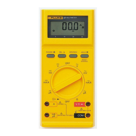
27
Multimeter
Advertisement
Table of Contents

Related Manuals for Fluke 27


Summary of Contents for Fluke 27
- Page 1 99 Washington Street Melrose, MA 02176-6024 For IEC 61010 CAT III Meters Only www.testequipmentdepot.com October 1998 Rev.1, 5/02 800-517-8431 © 1998-2002 Fluke Corporation. All rights reserved. Printed in U.S.A. 781-665-0780 FAX All product names are trademarks of their respective companies.
- Page 2 This warranty covers the original purchaser only and is not transferable. For ten years from the date of purchase, this warranty also covers the LCD. Thereafter, for the lifetime of the DMM, Fluke will replace the LCD for a fee based on then current component acquisition costs.
-
Page 3: Table Of Contents
® Table of Contents Title Page Multimeter Safety ......................1 Operating Features ....................... 4 Applications ........................8 Voltage, AC/DC ......................8 Current, AC/DC ......................8 Resistance and Diode Test/Continuity..............9 Resistance Measurement ..................9 Diode Test and Continuity ................... 9 Conductance ...................... - Page 4 Users Manual Specific Applications--Checking Capacitors.............. 12 Specific Applications--Noisy Resistance Measurements........... 15 Operator Maintenance ....................15 Battery Installation or Replacement ................16 Fuse Test ........................18 Fuse Replacement ....................18 General Maintenance....................19 Service ........................... 21 Specifications......................... 22...
-
Page 5: Multimeter Safety
Multimeter Safety • Multimeter Safety Do not use the meter if it operates abnormally. Protection may be impaired. Read this information before using the meter. This meter When in doubt, have the meter serviced. complies with EN 61010-1:1993, ANSI/ISA S82.01-1994 •... - Page 6 Users Manual • • Remove test leads from the meter before The use of makeshift fuses and the short- opening the battery door. circuiting of fuse holders is prohibited. • • Use only a properly installed, single 9 V To avoid false readings, which could lead battery to power the meter.
- Page 7 Multimeter Safety Table 2. Input Terminals and Limits Function Input Terminals Min Display Max Display Maximum Input Reading Reading Red Lead Black Lead 0.001 V 1000 V 1000 V 0.1 mV 320.0 mV 1000 V 0.1 e 32.00 Me 1000 V (nS) 0.01 nS 32.00 nS...
-
Page 8: Operating Features
Users Manual Operating Features Milliamps or amperes dc The following features are keyed by number to the Microamps dc illustration inside the front cover. Milliamps or amperes ac A Digital Display Microamps ac 3200 count, liquid crystal display with automatic decimal CT Volt, Ohms, Diode Test Input point positioning. - Page 9 Operating Features function selector rotary switch in the mA/A position (ac or counts (without overloading the input), OF (overflow) is dc). displayed. The Relative mode selects manual ranging; changing ranges automatically exits the Relative mode. G RANGE R Manual Range Mode I MIN/MAX Mode Pushbutton Pushbutton Press momentarily to enter MIN/MAX mode, press again...
- Page 10 Users Manual ® J HOLD H Touch Hold L MAX Maximum Annunciator Mode Pushbutton Indicates that the meter is in the MIN/MAX recording ® Press momentarily to enter Touch Hold mode. In Touch mode, and the value displayed is the maximum digital ®...
- Page 11 Operating Features T N Low Battery Annunciator nS converts to megohms. (Example: 2 nS converts to 500 Me.) Use for measuring resistance above 32 megohms. Select e, open test leads, press RANGE button twice. Battery voltage is tested each time the function switch is moved to a new position.
-
Page 12: Applications
Users Manual X Beeper (not illustrated) Current, AC/DC WWarning The beeper can produce beeps, clicks, or a continuous tone. It is used for audible indication in the diode test To avoid electric shock or personal injury: mode, when operating the push buttons, and when a new ®... -
Page 13: Resistance And Diode Test/Continuity
Voltage is developed across the component(s) under test To avoid possible damage to the meter or to by a test current output from the Fluke 27. Voltages the equipment under test, disconnect circuit greater than 2.08 V or open test leads produce an power and discharge all high voltage overload (OL) condition. -
Page 14: Conductance
Conductance measurements are displayed in test leads to the Fluke 27, and (with the leads nanosiemens (nS). Calculate megohms by dividing 1000 open) read the residual leakage in by the nanosiemens displayed (1000/nS is equivalent to nanosiemens. -
Page 15: Analog Bar Graph Application
(R) is not displayed, the Fluke inherent in needle movements. 27 automatically switches to the next high range if the input exceeds approximately 3260 counts A negative (-) annunciator is displayed at the left end of... -
Page 16: Specific Applications--Nulling
Specific Applications--Nulling The Fluke 27 bar graph is ideal for nulling adjustments. The analog bar graph, however, will display at least one As an adjustment approaches zero, fewer bar graph segment the moment the contact opens. - Page 17 Analog Bar Graph Application charges the capacitor and the needle slowly moves back In a fixed range (using manual range mode), the time it to the open (infinite ohms) position. The higher resistance takes for the bar graph to extend from zero to full scale ranges offer increased sensitivity for checking smaller indicates the approximate capacitance value.
- Page 18 Users Manual Table 3. Capacitance Vs. Time to Full Scale Capacitance Resistance Range 320 e Value 3.2 ke 32 ke 320 ke 3.2 Me 32 Me 10,000 µF 4 sec 33 sec 5 min 1,000 µF 4 sec 30 sec 100 µF 3 sec 28 sec...
-
Page 19: Specific Applications--Noisy Resistance Measurements
• When servicing the meter, use only specified replacement parts. The Fluke 27 resistance measurement circuit is designed to tolerate ac noise far better than the usual DMM. • Before closing battery door, make sure Readable 2-kilohm readings can be obtained even in the fuse cover is in place. -
Page 20: Battery Installation Or Replacement
A single 9V battery (NEDA 1604, 6F22, or 006P) supplies Snap the battery connector to the terminals on the power to operate the Fluke 27. Referring to Figure 1, use new battery, then slide the battery into the battery the following procedure to replace the Fluke 27 battery: compartment. - Page 21 Operator Maintenance Battery cover Fuse cover Battery Battery connector ye1f.eps Figure 1. Battery and Fuse Replacement...
-
Page 22: Fuse Test
Referring to Figure 1, use the following procedure to To prevent arc blast and resulting injury, check or replace the Fluke 27 fuses: install only the EXACT replacement fuse Perform steps 1 through 4 of the battery replacement listed in Table 4. -
Page 23: General Maintenance
Clean the case with a damp cloth and detergent; do not use abrasives or solvents. MP61 Fuse Cover 665031 The Fluke 27 is sealed to protect the instrument. To TL75* Test Lead Set maintain proper sealing, open only the battery/fuse AC70* Allicator Clip Set compartment. - Page 24 Users Manual AC70 Alligator Clips MP61 MP12 TL75 MP11 MP15 Test Lead Set MP16 MP14 ye2c.eps Figure 2. Replaceable Parts...
-
Page 25: Service
Service Service To contact Fluke, call one of the following telephone numbers: USA: 1-888-99-FLUKE (1-888-993-5853) Canada: 1-800-36-FLUKE (1-800-363-5853) Europe: +31 402-678-200 Japan: +81-3-3434-0181 Singapore: +65-738-5655 Anywhere in the world: +1-425-356-5500 Or, visit Fluke’s Web site at www.fluke.com. -
Page 26: Specifications
Users Manual Specifications Function Range Resolution Accuracy* 3.200 V 0.001 V ±(0.1%+1) 32.00 V 0.01 V ±(0.1%+1) 320.0 V 0.1 V ±(0.1%+1) 1000 V ±(0.1%+1) 320.0 mV 0.1 mV ±(0.1%+1) 320.0 e 0.1 e ±(0.3%+3)** 3.200 ke 0.001 ke ±(0.2% +1) 32.00 ke 0.01 ke ±(0.2% +1) - Page 27 Specifications Function Range Resolution Accuracy Typical Burden Voltage 32.00 mA 0.01 mA ±(0.75%+2) 5.6 mV/mA 320.0 mA 0.1 mA ±(0.75%+2) 5.6 mV/mA 10.00 A 0.01 A ±(0.75%+2) 50 mV/A 320.0 µA 0.1 µA ±(0.75%+2) 0.5 mV/µA 3200 µA 1 µA ±(0.75%+2) 0.5 mV/µA 32.00 mA...
- Page 28 Users Manual Function Overload Input Impedance Common Mode Rejection Ratio Normal Mode Rejection Protection* (Nominal) (1 ke unbalance) 1000 V rms 10 Me in // with<100 pF >120 dB at dc, 50 Hz, or 60 Hz >60 dB at 50 Hz or 60 Hz 1000 V rms 10 Me in // with<100 pF >120 dB at dc, 50 Hz, or 60 Hz...
- Page 29 Specifications Digital Display ..............3200 counts, updates 2/sec Analog Display ..............31 Segments, updates 25/sec Operating Temperature ............-15°C to 55°C, to -40°C for 20 minutes when taken from 20°C Storage Temperature Without Battery ..............-55°C to 85°C With Battery ..............-55°C to 60°C Electromagnetic Compatibility ...........
- Page 30 Users Manual Test Equipment Depot 99 Washington Street Melrose, MA 02176-6024 www.testequipmentdepot.com 800-517-8431 781-665-0780 FAX...