Table of Contents
Advertisement
Introduction
To avoid electric shock, do not perform any servicing other than that contained
in the Users or Service manual unless you are qualified to do so. These service
instructions are for use by qualified personnel only.
This Calibration Information for the 79/26 Series III Multimeter (hereafter known as "the Meter") provides
the information necessary to calibrate the meter and verify its performance. This information sheet provides
the following information:
•
Product specifications
•
Specifications
•
Basic Maintenance
•
Disassembly and reassembly
•
Performance test procedures
•
Calibration and calibration adjustment procedures
•
Replacement parts
For complete operating instructions, refer to the 79/26 Series III Instruction Sheet.
Service
The Meter has a limited lifetime warranty. To contact Fluke, call one of the following telephone numbers:
USA: 1-888-99-FLUKE (1-888-993-5853)
Canada: 1-800-36-FLUKE (1-800-363-5853)
Europe: +31 402-678-200
Japan: +81-3-3434-0181
Singapore: +65-738-5655
Anywhere in the world: +1-425-446-5500
For additional information about Fluke, its products, and services, visit Fluke's web site at:
www.fluke.com
PN 659349 December 1997 Rev.2, 3/00 ©1997, 1999, 2000 Fluke Corporation. All rights reserved. Printed in U.S.A.
WWarning
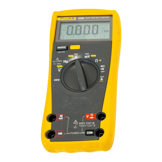
79/26
Series III Multimeter
Calibration Information
®
1
Advertisement
Table of Contents

Related Manuals for Fluke 79 III


Summary of Contents for Fluke 79 III
-
Page 1: Calibration Information
Replacement parts For complete operating instructions, refer to the 79/26 Series III Instruction Sheet. Service The Meter has a limited lifetime warranty. To contact Fluke, call one of the following telephone numbers: USA: 1-888-99-FLUKE (1-888-993-5853) Canada: 1-800-36-FLUKE (1-800-363-5853) Europe: +31 402-678-200... -
Page 2: Safety Information
79/26 Calibration Information Safety Information W Warning To avoid electric shock and personal injury: • Do not use the Meter if it is damaged. Before you use the Meter, inspect the case and look for cracks or missing plastic. Pay particular attention to the insulation surrounding the connectors. -
Page 3: Specifications
Series III Multimeter Specifications Specifications Specifications are in Table 1. Accuracy is specified for a period of one year after calibration, at 18 °C to 28 °C (64 °F to 82 °F) with relative humidity to 90 %. ac conversions are ac-coupled and true rms responding. - Page 4 79/26 Calibration Information Table 1. Specifications (cont.) Accuracy specifications are given as: ± ([% of reading] + number of least significant digits) ac readings are ac-coupled, true rms, and are valid from 5 % to 100 % of range. Add ±(2 % of reading + 2 % of range) for 1.4 <...
- Page 5 Series III Multimeter Specifications Table 1. Specifications (cont.) Function Range Resolution Accuracy Burden Voltage (Typical) ±(1.5 %+4) (45 Hz to 1 kHz) 4.000 mA 0.001 mA 11 mV/mA ±(1.5 %+2) 40.00 mA 0.01 mA 11 mV/mA ±(1.5 %+4) 0.001 A 0.03 V/A ±(1.5 %+2) 10.00 A*...
-
Page 6: Recommended Equipment
Table 2. Required Equipment Equipment Minimum Specifications Recommended Model DMM Calibrator DC Voltage: 0-600V Fluke 5100B, 5101B, plus Transconductance Accuracy: .05 % 5102B, 5700A) + 5220A or or Power Amplifier AC Voltage: 0 to 1000 V Fluke 5500A Multi-Product Accuracy: 0.2 %... -
Page 7: Basic Maintenance
Series III Multimeter Basic Maintenance Basic Maintenance WWarning To avoid electrical shock or personal injury, remove the test leads and any input signals before opening the case, and close and secure the case before operating the Meter. To prevent damage or injury, install only specified replacement fuses with the speed, amp interrupt rating, and voltage ratings that are shown in Table 12. -
Page 8: Replacing The Battery
79/26 Calibration Information Replacing the Battery W Warning To avoid false readings, which could lead to possible electric shock or personal injury, replace the battery as soon as the battery indicator M appears. The meter is powered by a single 9 V battery (NEDA 1604A/IEC 6LR61). Refer to Figure 2, and use the following procedure to replace the battery: 1. -
Page 9: Testing Fuses
Series III Multimeter Basic Maintenance Testing Fuses Refer to Figure 3, and use the following procedure to test the internal fuses of the Meter: 1. Turn the rotary switch to the Ω E position. 2. To test the F2 fuse (11 A, 1000 V), plug a test lead into the VΩG input terminal and touch the probe to the 10 A input terminal. -
Page 10: Replacing The Bottom Case Assembly
79/26 Calibration Information 4. Ensure that the rotary switch and circuit board switch are in the position. 5. Reinstall the top case as described in “Reassembling the Meter Case.” Replacing the Bottom Case Assembly Caution To avoid contamination with oil from the fingers, handle the pca by the edges or wear gloves. -
Page 11: Replacing The Lcd
Series III Multimeter Basic Maintenance Replacing the LCD Caution To prevent contamination, do not handle the conductive edges of the LCD or LCD interconnects. If they are contaminated, clean them with alcohol. Allow the alcohol to dry before reassembling. Refer to Figure 5, and use the following procedure to remove and replace the LCD: 1. -
Page 12: Performance Tests
79/26 Calibration Information Cleaning W Warning To avoid electrical shock or personal injury, do not reinstall the pca until it is completely dry. Caution To avoid damaging the meter, do not use aromatic hydrocarbons or chlorinated solvents for cleaning. These solutions will react with the plastics used in the instruments. -
Page 13: Testing The Dc Voltage Function
Series III Multimeter Performance Tests WWarning To avoid electric shock, connect the ground/common/low side of the dc calibrator to common on the UUT. Testing the DC Voltage Function 1. Set the UUT to L (V dc) and connect the dc voltage calibrator output to the VΩG and COM input terminals of the UUT. -
Page 14: Testing The Ac Voltage Function
79/26 Calibration Information Testing the AC Voltage Function W Warning To prevent possible electric shock, connect the ground/common/low side of the ac calibrator to common on the UUT. 1. Set the UUT to K (V ac), and connect the ac calibrator to the VΩG and COM input terminals. 2. -
Page 15: Testing The Ohms Function
Series III Multimeter Performance Tests Testing the Ohms Function 1. Set the UUT to Ω (ohms). 2. Connect the ohms calibrator or decade resistor to the VΩG and COM input terminals of the UUT. 3. Referring to Table 7, set the decade resistor or ohms calibrator to the resistance value indicated in steps 1 through 7. -
Page 16: Testing The Capacitance Function
79/26 Calibration Information Testing the Capacitance Function 1. Set the UUT to Ω E and connect the decade capacitor output to the VΩG and COM input terminals of the UUT. 2. Press the yellow button to select the capacitance function. 3. -
Page 17: Testing The Dc And Ac Current Function
Series III Multimeter Performance Tests Testing the DC and AC Current Function 1. Set the UUT rotary switch to amps. 2. Set the output of the current calibrator to standby and connect it to the 40 mA and COM input terminals of the UUT. -
Page 18: Calibration Adjustment
79/26 Calibration Information Calibration Adjustment Calibrate the meter once a year to ensure that it performs according to specifications. Calibration adjustment points are identified in Figure 7. Use the following procedure to calibrate the Meter: 1. Set the dc voltage calibrator to 0 volts. 2. -
Page 19: Lo-Ohms Calibration
Series III Multimeter Lo-Ohms Calibration Lo-Ohms Calibration Note For the Fluke 26 or 79 Series III with a serial number greater than 71220000, use the following procedure. 1. Perform the calibration procedure described under the heading Calibration Adjustment in this document. -
Page 20: Replacement Parts
79/26 Calibration Information Replacement Parts Replacement parts are listed in Table 12 and shown in Figure 8. Table 12. Replacement Parts Item Parts Part Number Quantity Top case assembly 659216 Bottom case assembly 659208 Fuse: F44/100 A, 1000 VAC/DC, Min interrupt Rating 10 kA 943121 F11 A, 1000 VAC/DC, Min Interrupt Rating 17 kA 943118...