Fluke 27-II User Manual
Digital multimeters
Hide thumbs
Also See for 27-II:
- Quick reference manual (2 pages) ,
- Calibration information manual (29 pages)
Table of Contents
Advertisement
Quick Links
Advertisement
Table of Contents

Related Manuals for Fluke 27-II


Summary of Contents for Fluke 27-II
- Page 1 ® 27 II/28 II Digital Multimeters Users Manual September 2009, Rev. 1, 10/10 © 2009, 2010 Fluke Corporation. All rights reserved. Specifications are subject to change without notice. All product names are trademarks of their respective companies.
- Page 2 Lifetime Limited Warranty Each Fluke 20, 70, 80, 170, 180 and 280 Series DMM will be free from defects in material and workmanship for its lifetime. As used herein, “lifetime” is defined as seven years after Fluke discontinues manufacturing the product, but the warranty period shall be at least ten years from the date of purchase.
-
Page 3: Table Of Contents
Table of Contents Title Page Introduction ........................1 How to Contact Fluke ..................... 1 Safety Information ......................2 Features ......................... 6 Automatic Power-Off ....................13 Input Alert™ Feature ....................13 Power-Up Options ..................... 13 How to Make Measurements..................15 AC and DC Voltage Measurements................15 Zero Input Behavior of True-rms Meters (28 II) ............ - Page 4 27 II/28 II Users Manual Capacitance Measurements ..................23 Diode Tests....................... 24 AC or DC Current Measurements ................26 Frequency Measurements ..................29 Duty Cycle Measurements ..................31 How to Determine Pulse Width ................. 32 Bargraph........................32 Zoom Mode (Power Up Option Only)................ 33 Uses for the Zoom Mode ..................
- Page 5 Contents (continued) Diode ......................... 51 Frequency ......................... 51 Frequency Counter Sensitivity and Trigger Levels ............ 51 Duty Cycle (Vdc and mVdc) ..................52 Input Characteristics....................52 MIN MAX Recording....................53...
- Page 6 27 II/28 II Users Manual...
- Page 7 List of Tables Table Title Page Symbols..........................5 Inputs ............................ 6 Rotary Switch Positions......................7 Pushbuttons .......................... 8 Display Features ........................11 Power-Up Options ......................... 14 Functions and Trigger Levels for Frequency Measurements..........30 MIN MAX Functions ......................35 Replacement Parts ........................ 41 Accessories ...........................
- Page 8 27 II/28 II Users Manual...
- Page 9 List of Figures Figure Title Page Display Features ........................11 AC and DC Voltage Measurements ..................15 Low-Pass Filter........................17 Continuity Tests........................19 Resistance Measurements ....................21 Capacitance Measurements....................23 Diode Tests ........................... 25 Current Measurements......................27 Components of Duty Cycle Measurements ................31 Current Fuse Test .........................
- Page 10 27 II/28 II Users Manual viii...
-
Page 11: Introduction
Introduction How to Contact Fluke To contact Fluke, call one of the following telephone XW Warning numbers: Read “Safety Information” before using the Technical Support USA: 1-800-44-FLUKE (1-800- Meter. 443-5853) Except where noted, the descriptions and instructions in this manual refer to both Series II Models 27 and 28 Calibration/Repair USA: 1-888-99-FLUKE (1-888- multimeters (hereafter referred to as “the Meter”). -
Page 12: Safety Information
27 II/28 II Users Manual Safety Information XWWarning To avoid possible electric shock or personal The Meter complies with: injury, follow these guidelines: ISA-82.02.01 Use this Meter only as specified in this CAN/CSA-C22.2 No. 61010-1-04 manual or the protection provided by the IEC Standard No. - Page 13 Digital Multimeters Safety Information Inspect the test leads for damaged Use the proper terminals, function, and insulation or exposed metal. Check the range for measurements. test leads for continuity. Replace Avoid working alone. damaged test leads before you use the When measuring current, turn off circuit Meter.
- Page 14 27 II/28 II Users Manual When servicing the Meter, use only This multimeter is not to be used to specified replacement parts. check electrical blasting circuits. This multimeter is not to be connected to When using probes, keep fingers behind an electrically energized circuit in an the finger guards on the probes.
- Page 15 United States Department of Labor, Mine μ Diode Safety and Health Administration. Inspected and licensed by TÜV Product ® Conforms to relevant Australian standards. Services. Do not dispose of this product as unsorted municipal waste. Go to Fluke’s website for recycling information.
-
Page 16: Features
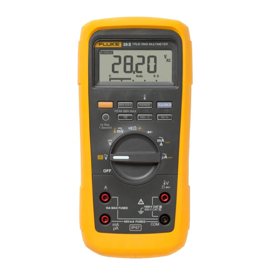
27 II/28 II Users Manual Features Tables 2 through 5 briefly describe the features of the Meter. Table 2. Inputs gaq112.eps Terminal Description Input for 0 A to 10.00 A current (10 - 20 A overload for 30 seconds maximum), current frequency, and duty cycle measurements. - Page 17 Digital Multimeters Features Table 3. Rotary Switch Positions Switch Position Function Any Position When the Meter is turned on, the Meter model number briefly appears on the display. K AC voltage measurement (yellow) Press for low-pass filter () (28 II only) DC voltage measurement 600 mV dc voltage range ...
- Page 18 27 II/28 II Users Manual Table 4. Pushbuttons Switch Button Function Position Selects capacitance (Yellow) Selects temperature (28 II only) Selects ac low-pass filter function (28 II only) Switches between dc and ac current Switches between dc and ac current ...
- Page 19 Digital Multimeters Features Table 4. Pushbuttons (cont.) Switch Button Function Position Continuity Turns the continuity beeper on and off Switches between Peak (250 s) and Normal (100 ms) response times. (28 II only) MIN MAX recording Hz, Duty Toggles the meter to trigger on positive or negative slope.
- Page 20 27 II/28 II Users Manual Table 4. Pushbuttons (cont.) Button Switch Position Function Any switch Stores the present reading as a reference for subsequent readings. The display is position zeroed, and the stored reading is subtracted from all subsequent readings. (Relative mode) ...
- Page 21 Digital Multimeters Features Number Feature Indication Negative readings, In relative mode, this sign indicates that the present input is less than the stored reference. High voltage present at the input. Appears if the input voltage is 30 V ...
- Page 22 27 II/28 II Users Manual Table 5. Display Features (cont.) Number Feature Indication Number Feature Indication Degrees Celsius, Degrees C, F Warning: To Low battery. XW Fahrenheit avoid false readings, which could lead to possible electric 610000 mV Displays selected range ...
-
Page 23: Automatic Power-Off
Digital Multimeters Features Automatic Power-Off Table 5. Display Features (cont.) The Meter automatically turns off if you do not turn the rotary switch or press a button for 30 minutes. If MIN Number Feature Indication MAX Recording is enabled, the Meter will not power off. Overload condition is detected. - Page 24 27 II/28 II Users Manual Table 6. Power-Up Options Button Power-Up Option Disables automatic power-off feature (Meter normally powers off in 30 minutes). (Yellow) The Meter reads “PoFF” until is released. Enables the Meter’s calibration mode and prompts for a password. ...
-
Page 25: How To Make Measurements
Digital Multimeters How to Make Measurements How to Make Measurements AC Voltage The following sections describe how to make measurements with the Meter. Switch Box AC and DC Voltage Measurements Model 28 II features true-rms readings, which are accurate for distorted sine waves and other waveforms (with no dc offset) such as square waves, triangle waves, and staircase waves. -
Page 26: Zero Input Behavior Of True-Rms Meters (28 Ii)
27 II/28 II Users Manual When measuring voltage, the Meter acts approximately Low-Pass Filter (28 II) like a 10-M (10,000,000 ) impedance in parallel with The 28 II is equipped with an ac low-pass filter. When the circuit. This loading effect can cause measurement measuring ac voltage or ac frequency, press ... -
Page 27: Temperature Measurements (28 Ii)
Digital Multimeters How to Make Measurements XW Warning W Caution To avoid possible electric shock or personal To avoid possible damage to the Meter or injury, do not use the low-pass filter to verify other equipment, remember that while the the presence of hazardous voltages. -
Page 28: Continuity Tests
27 II/28 II Users Manual Continuity Tests To test for continuity, set up the Meter as shown in Figure 4. WCaution Press to turn the continuity beeper on or off. To avoid possible damage to the Meter or to the equipment under test, disconnect circuit The continuity function detects intermittent opens and power and discharge all high-voltage... - Page 29 Digital Multimeters How to Make Measurements For in-circuit tests, turn circuit power off. (closed) (open) Activates continuity beeper gaq103.eps Figure 4. Continuity Tests...
-
Page 30: Resistance Measurements
27 II/28 II Users Manual Resistance Measurements The following are some tips for measuring resistance: The measured value of a resistor in a circuit is often WCaution different from the resistor's rated value. To avoid possible damage to the Meter or to the equipment under test, disconnect circuit The test leads can add 0.1 to 0.2... - Page 31 Digital Multimeters How to Make Measurements Isolating a Potentiometer In-Circuit Resistance Measurements Circuit Power Disconnect Isolating a Resistor Disconnect gaq106.eps Figure 5. Resistance Measurements...
-
Page 32: How To Use Conductance For High Resistance Or Leakage Tests
27 II/28 II Users Manual How to Use Conductance for High Resistance or To measure conductance, set up the Meter for measuring resistance as shown in Figure 5, then press until Leakage Tests the nS indicator appears on the display. Conductance, the inverse of resistance, is the ability of a circuit to pass current. -
Page 33: Capacitance Measurements
Digital Multimeters How to Make Measurements Capacitance Measurements WCaution To avoid possible damage to the Meter or to Select the equipment under test, disconnect circuit Capacitance power and discharge all high-voltage capacitors before measuring capacitance. Use the dc voltage function to confirm that the capacitor is discharged. -
Page 34: Diode Tests
27 II/28 II Users Manual Diode Tests To test a diode out of a circuit, set up the Meter as shown in Figure 7. For forward-bias readings on any WCaution semiconductor component, place the red test lead on the To avoid possible damage to the Meter or to component's positive terminal and place the black lead on the equipment under test, disconnect circuit the component's negative terminal. - Page 35 Digital Multimeters How to Make Measurements Reverse Bias Forward Bias Typical Reading Single Beep Shorted Open Bad Diode Bad Diode gaq109.eps Figure 7. Diode Tests...
-
Page 36: Ac Or Dc Current Measurements
27 II/28 II Users Manual AC or DC Current Measurements The Meter's current ranges are 600.0 A, 6000 A, 60.00 mA, 400.0 mA, 6.000 A, and 10.00 A. XWWarning To measure current, refer to Figure 8 and proceed as To avoid possible electric shock or personal follows: injury, never attempt an in-circuit current measurement where the open-circuit... - Page 37 Digital Multimeters How to Make Measurements Total Current to Circuit Circuit Power: OFF to connect meter. ON for measurement. OFF to disconnect meter. Current Through One Component gaq107.eps Figure 8. Current Measurements...
- Page 38 27 II/28 II Users Manual The following are some tips for measuring current: If you are using the A terminal, set the rotary switch to mA/A. If you are using the mA/ A terminal, set the If the current reading is 0 and you are sure the Meter ...
-
Page 39: Frequency Measurements
Digital Multimeters How to Make Measurements Frequency Measurements The following are some tips for measuring frequency: The Meter measures the frequency of a voltage or current If a reading shows as 0 Hz or is unstable, the input signal by counting the number of times the signal crosses signal may be below or near the trigger level. - Page 40 27 II/28 II Users Manual Table 7. Functions and Trigger Levels for Frequency Measurements Approximate Function Range Typical Application Trigger Level 6 V, 60 V, 5 % of scale Most signals. 600 V, 1000 V 600 mV 30 mV High-frequency 5 V logic signals. (The dc-coupling of the L function can attenuate high-frequency logic signals, reducing their amplitude enough to interfere with triggering.) 600 mV...
-
Page 41: Duty Cycle Measurements
Digital Multimeters How to Make Measurements Duty Cycle Measurements For 5-V logic signals, use the 6-V dc range. For 12-V switching signals in automobiles, use the 60 V dc range. Duty cycle (or duty factor) is the percentage of time a For sine waves, use the lowest range that does not result signal is above or below a trigger level during one cycle in multiple triggering. -
Page 42: How To Determine Pulse Width
27 II/28 II Users Manual How to Determine Pulse Width Bargraph For a periodic waveform (its pattern repeats at equal time The analog bargraph functions like the needle on an intervals), you can determine the amount of time that the analog meter, but without the overshoot. -
Page 43: Zoom Mode (Power Up Option Only)
Digital Multimeters HiRes Mode (28 II) Zoom Mode (Power Up Option Only) lights, press twice to set a new reference; then continue with the adjustment. To use the Rel Zoom Bargraph: HiRes Mode (28 II) Hold down while turning the Meter on. The display reads “2rEL”. -
Page 44: Min Max Recording Mode
27 II/28 II Users Manual calculating power consumption, or estimating the MIN MAX Recording Mode percentage of time a circuit is active. The MIN MAX mode records minimum and maximum input values. When the inputs go below the recorded Min Max records the signal extremes lasting longer than minimum value or above the recorded maximum value, 100 ms. - Page 45 Digital Multimeters Smooth Feature (Power Up Option Only) Table 8. MIN MAX Functions Button MIN MAX Function Enter MIN MAX recording mode. The Meter is locked in the range displayed before you entered MIN MAX mode. (Select the desired measurement function and range before ...
-
Page 46: Autohold Mode
27 II/28 II Users Manual AutoHOLD Mode Relative Mode Selecting relative mode ( ) causes the Meter to zero XWWarning the display and store the present reading as the reference To avoid possible electric shock or personal for subsequent measurements. The Meter is locked into injury, do not use AutoHOLD mode to the range selected when you pressed ... -
Page 47: Maintenance
Digital Multimeters Maintenance Maintenance Fuse Test As shown in Figure 10, with the Meter in the XWWarning function, insert a test lead into the jack and place the To avoid possible electric shock or personal probe tip on the other end of the test lead against the injury, repairs or servicing not covered in metal of the current input jack. -
Page 48: How To Replace The Batteries
27 II/28 II Users Manual How to Replace the Batteries Replace the batteries with three AA batteries Good 0.44 A fuse: 0.995 kΩ to (NEDA 15A IEC LR6). 1.005 kΩ XWWarning Replace fuse: OL To avoid false readings, which could lead to possible electric shock or personal injury, Touch top half replace the battery as soon as the battery... -
Page 49: How To Replace The Fuses
To order parts and accessories, refer to “How to Contact Gently lift out the fuse compartment door () from Fluke”. the fuse compartment. Remove the fuse by gently prying one end loose, then sliding the fuse out of its bracket (). - Page 50 27 II/28 II Users Manual gaq10.eps Figure 11. Battery and Fuse Replacement...
- Page 51 Digital Multimeters Service and Parts Table 9. Replacement Parts Fluke Part or Model Description Qty. Number Battery, AA 1.5 V 376756 Fuse, 0.440 A, 1000 V, FAST 943121 Fuse, 11 A, 1000 V, FAST 803293 Fuse Access Door 3400480 Screw...
- Page 52 27 II/28 II Users Manual Screw AC72 Alligator Clips Battery Door Battery Gasket Door Holster TL75 Test Lead Set Battery AA 1.5 V Fuse Fuse Cap Access Door Fuse 11 A, 1000 V, Fast 27 II/28 II Users Manual CD Fuse 80BK-A Integrated DMM 27 II/28 II...
- Page 53 Silicone test lead set with probes TL220 Industrial Test Lead Set TL224 Test Lead Set, Heat-Resistant Silicone Modular Test Probes, Flat Blade, Slim Reach Test Probes, 4 mm diameter, Slim Reach Fluke accessories are available from an authorized Fluke distributor.
-
Page 54: General Specifications
27 II/28 II Users Manual General Specifications Maximum voltage between any terminal and earth ground..........1000 V rms W Fuse for mA inputs ..........440 mA, 1000 V FAST Fuse W Fuse for A inputs ............. 11 A, 1000 V FAST Fuse Display Digital ................ - Page 55 Digital Multimeters General Specifications Electromagnetic Compatibility (EN 61326-1:1997)..In an RF field of 3 V/M, accuracy = specified accuracy +20 counts, except 600 A dc range total accuracy = specified accuracy +60 counts. Temperature not specified Relative Humidity ............0 % to 95 % (0 C to 35 C) 0 % to 70 % (35 C to 55 C) Battery Type..............3 AA Alkaline batteries, NEDA 15A IEC LR6, MSHA approved for use with three Energizer P/N E91 or three Duracell P/N MN1500 1.5 Volt, AA alkaline batteries...
-
Page 56: Detailed Specifications
27 II/28 II Users Manual Detailed Specifications For all detailed specifications: Accuracy is specified for 2 years after calibration, at operating temperatures of 18 C to 28 C, with relative humidity at 0 % to 95 %. Accuracy specifications take the form of ([% of Reading] + [Number of least-significant digits]). For Model 28 II in the 4 ½-digit mode, multiply the number of least-significant digits (counts) by 10. -
Page 57: Ac Voltage
Digital Multimeters Detailed Specifications 28 II AC Voltage AC conversions are ac-coupled and valid from 3 % to 100 % of range. Accuracy Range Resolution 45 – 65 Hz 15 – 200 Hz 200 – 440 Hz 440 Hz – 1 kHz 1 –... -
Page 58: Dc Voltage, Conductance, And Resistance
27 II/28 II Users Manual DC Voltage, Conductance, and Resistance Function Range Resolution Accuracy mV dc 600.0 mV 0.1 mV (0.1 % + 1) 6.000 V 0.001 V 60.00 V 0.01 V V dc (0.05 % + 1) 600.0 V 0.1 V 1000 V 600.0... -
Page 59: Temperature (28 Ii Only)
Digital Multimeters Detailed Specifications Temperature (28 II Only) [1,2] Range Resolution Accuracy -200 C to +1090 C 0.1 C (1.0 % + 10) -328 F to +1994 F 0.1 F (1.0 % + 18) Does not include error of the thermocouple probe. Accuracy specification assumes ambient temperature stable to 1 C. -
Page 60: Dc Current
27 II/28 II Users Manual DC Current Accuracy Function Range Resolution Burden Voltage 27 II 28 II 600.0 A 0.1 A 100 V/ A (0.2 % + 4) (0.2 % + 4) A dc 6000 A 100 V/ A (0.2 % + 2) (0.2 % + 2) 60.00 mA 0.01 mA... -
Page 61: Diode
Digital Multimeters Detailed Specifications Diode Range Resolution Accuracy 2.000 V 0.001 V (1.0 % + 1) Frequency Range Resolution Accuracy 199.99 Hz 0.01 Hz 1999.9 Hz 0.1 Hz (0.005 % + 1) 19.999 kHz 0.001 kHz 199.99 kHz 0.01 kHz >200 kHz 0.1 kHz Unspecified... -
Page 62: Duty Cycle (Vdc And Mvdc)
27 II/28 II Users Manual Duty Cycle (Vdc and mVdc) Range Accuracy 0.0 % to 99.9 % Within (0.2 % per kHz + 0.1 %) for rise times < 1 s. 0.5 Hz to 200 kHz, pulse width >2 s. Pulse width range is determined by the frequency by the frequency of the signal. Input Characteristics Input Common Mode... -
Page 63: Min Max Recording
Digital Multimeters Detailed Specifications MIN MAX Recording Nominal Response Accuracy 27 II 28 II Specified accuracy 12 counts for changes 100 ms to 80 % >200 ms in duration ( 40 counts in ac with beeper on) 100 ms to 80 % Specified accuracy 12 counts for (dc functions) changes >200 ms in duration... - Page 64 27 II/28 II Users Manual...