Table of Contents
Advertisement
Advertisement
Table of Contents

Related Manuals for Alcatel-Lucent OmniPCX Office RCE Small


Summary of Contents for Alcatel-Lucent OmniPCX Office RCE Small
- Page 1 Installation Manual Release 9.1 - July 2013...
- Page 2 Legal notice: Alcatel, Lucent, Alcatel-Lucent and the Alcatel-Lucent logo are trademarks of Alcatel-Lucent. All other trademarks are the property of their respective owners. The information presented is subject to change without notice. Alcatel-Lucent assumes no responsibility for inaccuracies contained herein.
-
Page 3: Table Of Contents
Protection against Interferences ..............Chapter 2 Hardware: Platform and Interfaces Overview ....................Platforms ....................OmniPCX Office RCE Compact ..............OmniPCX Office RCE Small ................OmniPCX Office RCE Medium ..............OmniPCX Office RCE Large ................. Installation ....................Overview ......................Equipment .................... - Page 4 Detailed description ..................Chapter 3 System Services Software Licence Management ............Software licence management ..............Software Keys ..................Voice Services Available in "Limited" Mode ..........Software Key Change ..................Detailed description ................Services controlled by the "Main" software key ..........Services controlled by the “CTI”...
- Page 5 Managed services ..................3.16 Mobility on GSM ................... 3.16 Chapter 4 Installation and Cabling Presentation ..................... Location of Unit ....................Environment ....................Connections and Cabling ..............Detailed description ..................Power Supply ..................4.19 Installation procedure ................... 4.19 SIP Terminals ..................4.34 8002/8012 Desk Phone ................
- Page 6 Hardware description ..................4.85 Hardware configuration ................4.87 External connections ..................4.88 Intelligent Base Stations ..............4.91 Detailed description ..................4.91 Safety rules ....................4.99 IP-DECT Base Stations ..............4.102 Detailed description ..................4.102 PIMphony ....................4.104 Overview ..................... 4.104 Additional Information .................
- Page 7 System Startup from a Phone Set ............ Configuration procedure ................System Startup from OMC ..............6.14 Overview ....................... 6.15 Installation procedure ................... 6.15 Accessing the System .................. 6.16 Downloading the Software ................6.23 Services provided ..................6.25 Chapter 7 Maintenance Services Maintenance Level 1 ................
- Page 8 .........................................................................................................................................................................................................................................
-
Page 9: Preliminary
Safety rules 1.2.1.1 Safety Declaration We, Alcatel-Lucent Enterprise 32, avenue Kléber 92707 Colombes Cedex - France, declare that the products presented in this manual conform to the essential requirements of Directive 1999/CE/5 of the European Parliament and Council. Any unauthorized modification to the products invalidates this declaration of conformance. -
Page 10: General Recommendations
Copyright 2001 - 2000 Datalight, Inc., All Rights Reserved. In order to better serve its customers, Alcatel-Lucent Enterprise reserves the right to modify the characteristics of its products without notice. Alcatel-Lucent Enterprise - 32, avenue Kléber F-92707 Colombes Cedex RCS Paris 602 033 185. 1.2.1.2... - Page 11 The EC labeling indicates that this product conforms to the EC directives currently in force, in particular: 89/336/EEC (Electromagnetic compatibility) 73/23/EEC (Low Voltage) R&TTE 1999/5/EC compliance 1999/519/EC (Specific Absorption Rate) 1.2.1.4 Interface Classification 1.2.1.4.1 OmniPCX Office RCE Small, Medium, Large SELV: Safety Extra Low Voltage TNV-3: Telecommunication Network Voltage...
- Page 12 Chapter Figure 1.4: OmniPCX Office RCE Small, Medium, Large 1.2.1.4.2 OmniPCX Office RCE Compact...
-
Page 13: Protection Against Interferences
Changes or modifications to this equipment, not expressly approved by ALCATEL-LUCENT,... - Page 14 Chapter may cause harmful interference and void the user’s authority to operate this equipment. Japan - VCCI (Voluntary Control Council for Interference) Translation : This is a Class B product based on the standard of the Voluntary Control Council for Interference from Information Technology Equipment (VCCI).
-
Page 15: Overview
(according to country). The stations are packaged separately. Platforms Alcatel-Lucent OmniPCX Office Communication Server is available in the following models: 2.2.1 OmniPCX Office RCE Compact 14 ports. 1 CPU slot + 1 MIX slot... - Page 16 The Mini-MIX daughter board, plugged on a PowerCPU booard, requires an OmniPCX Office RCE Compact, or, in case of migration from Release 7.1 or lower, a Compact Edition 2nd Generation. The Mini-MIX daughter board cannot be used on an Alcatel-Lucent OmniPCX Office Compact Edition.
-
Page 17: Omnipcx Office Rce Small
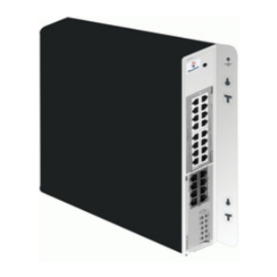
Slot 80 EN 01 for the first T0 access (80-001-01) Slot 80 EN 02 for the second T0 access (80-002-01) Slot 80 EN 09 for the first Z access (80-009-01) Slot 80 EN 10 for the second Z access (80-010-01) 2.2.2 OmniPCX Office RCE Small... -
Page 18: Omnipcx Office Rce Medium
Chapter 28 ports. 1 CPU slot 2 general-purpose slots (no SLI16 board). Energy consumption: 1 A (230 V) / 2 A (110 V) - 80 W. Dimension: H = 66 mm; W = 442 mm; D = 400 mm. Weight: 6 kg. 2.2.3 OmniPCX Office RCE Medium 56 ports. -
Page 19: Installation
Installation 2.3.1 Overview... -
Page 20: Equipment
Equipment shall be installed at the factory or in the field by submitter's trained personnel in accordance with the installation instruction provided with the equipment. Equipment 2.4.1 Boards and Options The following table lists the boards available on OmniPCX Office RCE Small, Medium, Large. Board Function Optional boards Connections... - Page 21 HSL1 board) MIX244 0, 2 or 4 T0 basic accesses + 4 ISDN network, analog Z ter- MIX248 or 8 UA interfaces + 4 or 8 Z in- minals and Alcatel-Lucent 9 MIX284 terfaces series or Alcatel Reflexes MIX484 stations...
- Page 22 Chapter As of R8.0, the PowerCPU board performs the CPU functions of an OmniPCX Office system. 2.4.2.1.1 Function of the LEDs Name Color Function Green CPU functioning LED (flashing) POWER Red/Green Mains operation: steady green LED Battery operation: steady yellow LED Idle: flashing red LED System shut down: steady red LED Red/Green...
- Page 23 Board used for connecting up digital terminals or DECT 4070 IO/EO base stations. The UAI16-1 board is used to power terminals connected to the 16 interfaces remotely from an EPS48 external power supply connected to interface 1 via an external adapter cable (splitter). Caution: Only use EPS48 power supplies and the splitters provided.
- Page 24 2.4.2.7 PRA Boards This board provides 1 primary access for connecting the Alcatel-Lucent OmniPCX Office Communication Server system to the ISDN digital public network or to private networks: PRA -T2, DASS2, DLT2 : 30 x 64-Kbps B-channels + 1 x 64-Kbps D-channel; 2048 Kbps.
- Page 25 T2 Name T1 Name Function BUSY BUSY B-channels busy (red LED lights up if at least 1 B-channel is busy) RAI (ATD) Remote frame alarm (red LED lights up on alarm) AIS (SIA2M) Too many "1's in the 2-Mbit binary train (red LED lights up on alarm) NOS (MS) NSIG Absence of 2-Mbit signal (red LED lights up on alarm)
- Page 26 Chapter Each category-5 RJ45 connector has 2 green LEDs: Left LED = link status and activity: • off: link disconnected • on: link connected • blinking: link active Right LED = full duplex/collision: • off: Half Duplex • on: Full Duplex •...
- Page 27 Daughter Board Provision on PowerCPU Board The table below presents the daughter boards which can be provided on the PowerCPU board, according to the platform used. Daughter Boards OmniPCX Office RCE Compact OmniPCX Office RCE Small, Medium, Large ARMADA VoIP32 HSL1 HSL2...
- Page 28 R7.1 or lower, in a Compact Edition 2nd Generation, equipped with a PowerCPU board. Figure 2.22: Example of Daughter Boards on PowerCPU 2.4.2.14 Provision By Platform 2.4.2.14.1 OmniPCX Office RCE Compact Board MIX Slot CPU Slot PowerCPU Mandatory MIX x/y/z AMIX-1 x/y/z 2.4.2.14.2 OmniPCX Office RCE Small 2-14...
- Page 29 Boards Slots 1-2 CPU Slot PowerCPU Mandatory MIX x/y/z AMIX-1 x/y/z UAI4, UAI8, UAI16, UAI16-1 SLI4, SLI8, SLI4-1, SLI8-1, SLI4-2, SLI8-2 SLI16, SLI16-1, SLI16-2 PRA-T2, PRA-T1, DASS2, DLT2, T1-CAS, PCM R2 APA4, APA8 DDI2, DD14 BRA2, BRA4, BRA8 LANX8, LANX16, LANX16-1, LANX8-2, LANX16-2 2.4.2.14.3 OmniPCX Office RCE Medium Boards...
- Page 30 Chapter 2.4.2.14.4 OmniPCX Office RCE Large Boards Slot 1 Slots 2-3-4 Slots5-6-7-8 CPU Slot PowerCPU Mandatory MIX x/y/z AMIX-1 x/y/z UAI4, UAI8 UAI16, UAI16-1 SLI4, SLI8, SLI16, SLI4-1, SLI8-1, SLI16-1, SLI4-2, SLI8-2, SLI16-2 PRA-T2, PRA-T1, DASS2, DLT2, T1-CAS, PCM R2 APA4 APA8 DDI2, DD14...
-
Page 31: Software Licence Management
3.1.1 Software licence management On an Alcatel-Lucent OmniPCX Office Communication Server several types of devices may be connected, several services may be offered and several applications may run. The purpose of the feature “Software Licence Management” is to define for a given system (i.e. -
Page 32: Voice Services Available In "Limited" Mode
Chapter the PRINC (PRINCIPAL) software key or MAIN for the system functions (voice, system feature, etc.) the CTI Software key for the CTI functions The software key corresponds to a text file where the name is the CPU hardware number with the .MSL (MAIN key) or .CSL (CTI key) extension. -
Page 33: Software Key Change
Software key -> Hardware serial number Send this serial number and the function levels required to Alcatel-Lucent Enterprise Load the key file Main.msl or CTI.csl from the Alcatel-Lucent Business Partner Internet site (this file can also be downloaded by the manufacturer) Downloading a new software key: •... -
Page 34: Services Controlled By The "Main" Software Key
Chapter 3.3.1 Services controlled by the "Main" software key The following table lists the functions controlled by the "Main" software key. If a software key is not present in the system, or is incorrect, the system starts in a limited state. The table also gives the limited state service levels, the granularity of upgrades, the maximum service level for each service, and if a hardware extension exists. - Page 35 Controlled services Relevant Values in Modularity Hardware software limited extension version mode Number of IP Phones (IP Touch) Number of PIMphony multimedia ter- minals VoIP GATEWAY Number of VoIP channels From R8.0 0 Number of VoIP trunk channels From R8.0 0 VOIP R1.0/R1.1 VoIP on application board...
- Page 36 Chapter Controlled services Relevant Values in Modularity Hardware software limited extension version mode MULTIPLE AUTOMATED ATTENDANT Number of tree structures: From R6.0 closed open 1 license for 1 tree structure 1 license for 5 tree structures Pay Per User (PPU) PPU activation From R5.0 R5 and R5.1: Not controlled by the system.
-
Page 37: Services Controlled By The "Cti" Software Key
Controlled services Relevant Values in Modularity Hardware software limited extension version mode Number of active Automatic Call Dis- From R3 5, 10, 20, or tribution agents 32 depend- ing on li- cense Automatic Call Distribution statistics From R3 closed open module Number of agent applications From R3... - Page 38 Number of sessions 25 (R1) 0 (from R2) Number of monitors 250 (R1) 0 (from R2) Features None Alcatel-Lucent OmniPCX Office Communication Server CALL CENTER Number of sessions Number of monitors Features None CSTA DESKTOP CLIENT Number of sessions Number of monitors...
-
Page 39: Descriptions
Controlled services Relevant Default Modularity software state version TAPI 2.1 SERVER Number of sessions Number of monitors Features None BUSY LAMP FIELD (BLF) Number of sessions Number of monitors Features None XML SERVER Number of sessions Number of monitors Features None PIMphony UNIFIED Number of sessions... -
Page 40: Standard Telephony
Chapter This section describes how the licenses affect the Alcatel-Lucent OmniPCX Office Communication Server. 3.4.2 Standard telephony The number of sets allowed can be changed without reset, it means that all the devices are accepted but the sets, which exceed the limit, are put out of service (as it would be done by OMC) due to a SWL reason. -
Page 41: Call Handling Features
IP-DECT subscribers has reached the maximum value indicated in the current license. 3.4.6 Call handling features 3.4.6.1 The same as for Alcatel-Lucent OmniPCX Office Communication Server. 3.4.6.2 DISA / DISA Transit The same as for Alcatel-Lucent OmniPCX Office Communication Server. -
Page 42: Internet Access (Relevant Up To R7.1)
Chapter In case of upgrade, a reset is necessary to take into account new MIX boards. In default state reached after 30 days of temporary state, the license 2B channels on mixed board is set to 24. 3.4.8 Internet access (relevant up to R7.1) Several services are defined in the license: Access &... -
Page 43: Lan Telephony
2 access on CPU III main, 16 access on CoCPU) 3.4.12 Lan telephony In the license, two counters are defined: The number of TSC/IP and number of PIMphony IP: Their processing is the same as for other sets. The number of allowed NOE/IP are included into the TSC/IP counters. 3.4.13 VoIP Gateway 3.4.13.1... -
Page 44: Music On Hold (Moh)
Chapter For example: If by configuration, you remove the two ports from the default attendant group because you do not have automated attendant (it is not mandatory). Then, if there is a SWL upgrade, which permits 4 ports and automated attendant, you will need to create two new ports, present in the attendant default group and in the first hunting group. -
Page 45: Languages
3.4.16.2 Call accounting over IP This license is required for printing on the fly or for using external accounting applications. Output data will be provided in a simple XML format interface. This license must be opened for OHL needs. 3.4.16.3 Local calls (from R8.1) Specific license for each country 3.4.17... -
Page 46: Managed Services
Chapter The Alcatel-Lucent OmniPCX Office Communication Server provides an embedded Linux based ACD (automatic call distribution) solution. The following capacities are defined through licenses: 1) 2) 3) 1. The Number of group: 8 groups 2. The number of active agents: 5, 10, 20 or 32 3. - Page 47 This license item is a global parameter (on/off) that allows or not, when a correspondent name is searched on 8082 My IC Phone and My IC Mobile for iPhone, to extend the search to an external LDAP server. 3.4.21.6 Number of SIP Companion (from R9.1) The number of My IC Mobile for iPhone users allowed to use the SIP mode.
- Page 48 Chapter 3-18...
-
Page 49: Presentation
Compact platform which can also be fixed directly to the wall. In both cases, use the hole drilling template supplied with the platform. 2. Mounted in a rack: the OmniPCX Office RCE Small, Medium, Large platforms are mounted in the rack using the fixing brackets supplied by the rack manufacturer, or using the optional 19"... - Page 50 Moreover, the weight of the equipment must be evenly distributed between the brackets. If mounting the Alcatel-Lucent OmniPCX Office Communication Server platform results in exceeding the load on the front supports (generally the total weight divided by two), the...
-
Page 51: Environment
When superposing them vertically, they should be separated by at least 10 cm. Verify that the cables connecting the Alcatel-Lucent OmniPCX Office Communication Server or other equipment, or the supports for the housing structure (19" rack for example) do not obstruct the air flow through the platform. - Page 52 Chapter All outputs are made using Female RJ45 connectors. 4.2.1.1.1 PowerCPU Board RJ45 pin CenRG SLI1/SLI2 Ground +12 V CenRg A ZA1 CenRG Ground +12 V CenRg A CONFIG RMTRES Ground MODULE1 ISDN T01 MODULE2 ISDN T02 Audio In Audio Audio Audio Audio...
- Page 53 1 to 16: connecting analog Z terminals. 4.2.1.1.3 UAI Board RJ45 pin 1 to 16 (UAI) 1 to 16: connection of digital terminals or DECT 4070 IO/EO base stations. 4.2.1.1.4 UAI-1 Board RJ45 pin 2 to 16 1 : connection of an EPS48 external power supply + connection of digital terminals or DECT 4070 IO/EO base stations.
- Page 54 Chapter RJ45 pin Ports 1 to 14 GE1, GE2 TR0+ TR0- TR1+ TR2+ TR2- TR1- TR3+ TR3- Ports 1 to 14: 10/100 BT ports. GE1, GE2: 10/100/1000 BT ports. 4.2.1.1.9 APA Board RJ45 pin Output 1 ZSETB ZSETA LB-Ring LA-Tip Outputs 2 to 8 LB-Ring LA-Tip...
- Page 55 4.2.1.4 Connecting Terminals 4.2.1.4.1 Connection of Digital Terminals The terminals are equipped with a cable and a self-acting switch that plugs into the wall socket. Each terminal is connected up by a pair of 0.5 or 0.6 mm diameter wires. System - digital terminal distances: 0.5 mm SYT type cable: 800 m (station without option) or 600 m (station with S0 or Z option).
- Page 56 Chapter Connection with External Power Supply A splitter allows the separation of the UA peripheral connection and the EPS48 external power supply. 4.2.1.4.2 Connecting Analog Terminals The terminals are equipped with a cable and a self-acting switch that plugs into the wall socket.
- Page 57 Connection to the Public Network 4.2.1.5.1 Digital Public Network via T0 Access (or DLT0 Private Network) The Alcatel-Lucent OmniPCX Office Communication Server system can be installed near the digital network termination or at a certain distance (up to 350 m), as required.
- Page 58 Chapter The ISDN-EFM box must be installed as close as possible to the system (3 m maximum). All the box connections are made with straight RJ45-RJ45 cables. Output connector functions: BRA: connection of T0 access to be forwarded. NT: connection of ISDN network termination. S0: connection of forwarding S0 station.
- Page 59 4.2.1.5.2 Digital Public Network by T1 or T2 Access The diagram below shows a PRA-T2 board, but is equally applicable for a PRA-T1 board. 4-11...
- Page 60 Chapter The PRA board is connected to a digital line termination (DLT) by 2 symmetrical twisted pairs. Cable impedance: 120 Ohms +/- 20% between 200kHz and 1MHz; 120 Ohms +/- 10% at 1 MHz. Remark: We recommend using an L120-series cable (or the L204 equivalent). The distance T1-DLT or T2-DLT is limited by the amount of loss between the DLT and T1/T2, which must not exceed 6 dB at 1024 kHz.
- Page 61 4.2.1.5.4 Analog Public Network - Direct Dialing In. 4.2.1.6 Lan Connection The LANX8/LANX16 board is used to connect servers, PCs, IP terminals and external switches. 4-13...
- Page 62 Chapter Category 5 cable, FTP or STP, impedance 100 Ohms: maximum length 100 m. 4.2.1.7 Connecting Auxiliary Equipment All auxiliary equipment is connected via the AUDIO, AUX and DOORPHONE connectors of the PowerCPU board. 4.2.1.7.1 Connecting a Please-Wait Message Player This is connected via the AUDCTRL output (control contact open when idle) and the AUDIN input of the AUDIO connector.
- Page 63 Audio Input Characteristics: Input impedance : 600 Ohms Fuse Characteristics: Max. power : 10 W Max. voltage : 60 V Max. current : 500 mA The contacts of the alarm and doorphone controls have the same electrical characteristics as those indicated above. 4.2.1.7.2 Connecting a Background Music Tuner This is connected via the AUDIN input of the AUDIO connector.
- Page 64 Chapter 4.2.1.7.3 Connecting an Alarm The alarm is activated in the event of a false stopping of the system. It is connected via the ALARM output (control contact closed when idle) of the AUDIO connector. 4.2.1.7.4 Connecting a Broadcast Loudspeaker Broadcast loudspeakers are connected via the AUDOUT output of the AUDIO connector.
- Page 65 4.2.1.7.6 Connecting a Doorphone 2 doorphone types are available, depending on the operating mode used: Type A: relay-controlled doorphones (e.g. NPTT) Type B: doorphones controlled by MF Q23 signals requiring an SLI interface (e.g. TELEMINI and UNIVERSAL DOORPHONE) The doorphone interface comprises an intercom and an optional latch powered by the mains supply through a SELV (Safety Extra Low Voltage) transformer.
- Page 66 Chapter A single doorphone with doorstrike may be connected to the system. The system also allows for the connection of 2 doorphones without latch. Connecting a Telemini and Universal Doorphone These doorphones require the use of a Z station interface. Several of these doorphones can be connected to the system;...
-
Page 67: Power Supply
The battery fuse is located on the board and requires the back panel to be dismantled to gain access. It has the following characteristics: OmniPCX Office RCE Small and OmniPCX Office RCE Large: 6.3 A fast, low cutoff (F 6.3 AL/250 V). - Page 68 OmniPCX Office 12V, 4-hour, stack version 1 battery 3EH 76177 AA RCE Compact 12V, 8-hour, stack version Up to 2 batteries 3EH 76177 AD Note: The external battery units for OmniPCX Office RCE Small, Medium, Large platforms are pre-wired and 4-20...
- Page 69 The connection procedure is the same for OmniPCX Office RCE Medium and OmniPCX Office RCE Large platforms, but is different for OmniPCX Office RCE Small platforms. Preparing an External Battery Unit (Rack Version)
- Page 70 Batteries must be charged prior to installation. Procedure for 12 V stack version (for OmniPCX Office RCE Small and OmniPCX Office RCE Medium platforms) The 12 V stack version of the external battery unit can be used with OmniPCX Office RCE Small and OmniPCX Office RCE Medium platforms.
- Page 71 black) and that there is no cable connected to the J1 connector (see the figure below). 2. Open the unit by removing the four screws (ST3.5x32) with a screwdriver (Phillips PH2). 3. Insert the batteries in the open unit as follows (also see the figure below): a.
- Page 72 Chapter 5. Connect the positive (red) terminals of the batteries as described below (and shown in the figure below). a. Connect the middle connector of the red wire to the positive (red) terminal of battery b. If required, connect the other connectors of the red wire to the positive (red) terminals of batteries B1 and B3.
- Page 73 1. Ensure that the ON/OFF switch on the external battery unit is set to the OFF position (0 or black) and that there is no cable connected to the unit (see the figure below). 2. Open the unit by removing the four screws (ST3.5x32) with a screwdriver (Phillips PH2). 3.
- Page 74 Chapter 5. Close the unit and secure it with the four screws. 6. Stick a label on the unit stating the date of the installation and the number of batteries installed. 7. If you wish to use two external battery units in parallel, continue as follows (also see figure below): a.
- Page 75 1. Stop the Alcatel-Lucent OmniPCX Office Communication Server system, and remove the power supply cord from the platform side. Disconnect the power supply cable on the platform side before handling the power supply. This operation disconnects the mains supply and the internal battery.
- Page 76 7. Put the upper cover back in place. 8. Connect the cable (with J1 connector) between the Alcatel-Lucent OmniPCX Office Communication Server system and the external unit. 9. Set the ON/OFF switch on the external battery unit to the ON position (I or red).
- Page 77 2. Insert the batteries in the open unit as follows (see the figure below): a. Place the first battery in the middle position (battery B1). b. If a second battery is to be used, place this battery in the remaining position (battery B2).
- Page 78 Connecting to the OmniPCX Office RCE Compact Platform 1. Switch off the Alcatel-Lucent OmniPCX Office Communication Server system and then: a. Unplug the power cable from the mains socket. b. Disconnect the mains adapter from the OmniPCX Office RCE Compact platform.
-
Page 79: Connecting A Ups
Note: If a hard disk is installed on an OmniPCX Office RCE Compact platform, it is MANDATORY to install the external battery unit, and the extBAT jumper of the PSXS-N MUST be set to YES. It is mandatory to use a power supply module PSXS-N with reference 3EH73072ACxx on an OmniPCX Office RCE Compact platform equipped with a PowerCPU board and a hard disk. - Page 80 Chapter It is connected via the mains socket at the rear of the platform: UPS Power: use the mains cable provided with the Alcatel-Lucent OmniPCX Office Communication Server module. UPS Connection - module: use the cable supplied with the UPS For an installation using 3 Alcatel-Lucent OmniPCX Office Communication Server modules, 2 UPSs are required: one feeds two of the modules, the other feeds the third module.
- Page 81 For performance and safety reasons, the whole system must always be coupled to the ground. The ground must be connected before any other connections. The ground protection connection terminal must always be connected to the ground. Protective grounding terminal shall be permanently connected to the ground. 4.3.1.5.2 OmniPCX Office RCE Compact OmniPCX Office RCE Compact platform is powered by an external power supply unit (100/240V).
-
Page 82: Sip Terminals
3. If necessary, configure the user name and password in OMC, refer to Configuring the user name and password in OMC Prerequisites The Alcatel-Lucent OmniPCX Office Communication Server version must be R9.0 or higher and the system must be operational For network configuration, any of the following must be implemented: •... - Page 83 Connecting the set This section describes how to connect an 8002/8012 Deskphone set to the LAN (Local Area Network). To connect the set to the LAN: 1. Plug an RJ45 cable between the set LAN connector and a port of the switch. Accessing the set administration menu 1.
- Page 84 ID. In the DHCP offer, the data within Option 43 corresponds to the client vendor ID specified in the request. In the case of 8002/8012 Deskphone sets, suboption 67 of option 43 provides the path of configuration files on the Alcatel-Lucent OmniPCX Office Communication Server. 4-36...
- Page 85 IP address Router IP address Subnet mask Option 66: IP address or name of the Alcatel-Lucent OmniPCX Office Communication Server:10443, for example 192.168.12.34:10443 Suboption 67 of option 43: the value of this sub-option corresponds to the DM Url.It must contain a string value set to /dmcfg/...
- Page 86 Use Default Port: press the OK button to confirm that the default port is not used (unchecked box) • DL Addr: press the OK button and enter IP address of the Alcatel-Lucent OmniPCX Office Communication Server server • DL Port: press the OK button and enter 10443 •...
-
Page 87: 8082 My Ic Phone
SIP phone disconnected from network / No SIP registration request from the phone SIP registration KO SIP registration request from SIP Phone rejec- ted by Alcatel-Lucent OmniPCX Office Com- munication Server Set unregistered SIP phone unregistered from Alcatel-Lucent OmniPCX Office Communication Server... - Page 88 Chapter Figure 4.41: 8082 My IC Phone set connectors 4.4.2.1.2 Commissioning the set This section describes how to commission the set in the two available initialization options: Static initialization: commissioning is manual on the set and through OMC Dynamic initialization (DHCP): no commissioning is needed, 8082 My IC Phone sets are fully plug &...
- Page 89 3. If necessary, configure the user name and password in OMC, refer to Configuring the user name and password in OMC Prerequisites The Alcatel-Lucent OmniPCX Office Communication Server version must be R810 or higher and the system must be operational For network configuration, any of the following must be implemented: •...
- Page 90 Chapter Initialize the 8082 My IC Phone set Selecting the initialization type The default initialization is dynamic Alcatel-Lucent Enterprise. To select the initialization type, refer to the following table. table 4.18: Initialization type selection Then the required ini- Further information...
- Page 91 Option 58: VLAN ID: this is sent as a suboption of option 43 Optionally, the DHCP offer can include the following parameters, which can also be configured locally on the terminal or on the Alcatel-Lucent OmniPCX Office Communication Server: Option 6: Domain Name Server (DNS primary and secondary) Option 15: Domain name Option 12: Host name (eg, ICTouch<MAC>)
- Page 92 Chapter • Enable and configure a DHCP User Class: this makes the set send the standard DHCP option 77 (User Class, RFC2132) within the DISCOVER and REQUEST DHCP messages. Using this option allows to define groups of terminals, and to attach these groups to different and independent Com Servers.
- Page 93 5. Select Loudspeaker 6. If your device is not Bluetooth®, plug it to the corresponding connector Traffic priority on the internal switch The 8082 My IC Phone set includes an internal LAN switch. This switch allows to connect a PC. The internal switch has three ports: A LAN port An internal port...
- Page 94 Communication Server 4.4.2.1.3 Video Call parameters The Alcatel-Lucent OmniPCX Management Console is used to enable the video call support for the 8082 My IC Phone sets. Once configured it is possible to make: Basic P2P video calls between 8082 My IC Phone (VHE-2) and any SIP phone with video support.
- Page 95 Country Type Video Camera Country Fre- quency (Default value in OMC) Brazil Costa-Rica Guatemala Haiti Honduras Mexico Panama 60 Hz Philippines Saudi Arabia Taiwan USA Venezuela Verizon All others 50 Hz Video Camera Refresh Cycle: defines the time interval between two full pictures refresh in seconds.
-
Page 96: Upgrading The Software
The default value for this parameter is 55. 4.4.2.1.5 Upgrading the software The Alcatel-Lucent OmniTouch™ 8082 My IC Phone set software is upgraded during OmniPCX Office software upgrade. Ensure the 8082 My IC Phone option is validated in the... - Page 97 This module presents all the actions required for commissioning 4135 IP Conference Phone sets. Figure 4.42: 4135 IP Conference Phone set layout The following figure illustrates the connectors on the base of each set. 4-49...
- Page 98 The 4135 IP Conference Phone is a SIP device which has no handset; it is dedicated to be used as central for conferences. Conferences are not managed by the system, but by the device itself. Up to four 4135 IP Conference Phones can be connected to the Alcatel-Lucent OmniPCX Office Communication Server. 4.4.3.1.2 Commissioning the set...
- Page 99 This paragraph applies to OMC configuration of sets initializing in static mode. In dynamic (DHCP) mode, the following operation is not mandatory but the server certificate must be exported from the Alcatel-Lucent OmniPCX Office Communication Server to the PC and can then be uploaded to the 4135 IP Conference Phone.
- Page 100 Select the initialization mode Initialize the 4135 IP Conference Phone set Selecting the initialization type The default initialization is dynamic Alcatel-Lucent Enterprise. To select the initialization type, refer to the table below. table 4.23: Initialization type selection Then the required ini-...
- Page 101 IP address Router IP address Subnet mask Option 66: IP address or name of the Alcatel-Lucent OmniPCX Office Communication Server:10443, for example 192.168.12.34:10443 Suboption 67 of option 43: the value of this sub-option must contain a string value set to...
- Page 102 3. Specify the destination path for the export and click OK: The selected path and the certificate file name are displayed in the Export Server Certificate window 4. Click the Export button: The certificate file is exported from the Alcatel-Lucent OmniPCX Office Communication Server to the specified file path in PC 5.
-
Page 103: Generic Sip Phones
Commissioning 4.4.4.1.1 Overview This module presents all the actions required for commissioning generic SIP sets. The List of supported SIP Phones is available on the Alcatel-Lucent Applications Partner Program (AAPP) web site. 4.4.4.1.2 Commissioning Generic SIP Sets This section describes how to commission a generic SIP Set. - Page 104 Chapter 3. Select IP terminal and enter a Name. 4. Select the newly created user in the list and select Basic SIP Phone or Open SIP Phone in the combo box. See the different features relating to basic or open SIP modes: List of Services Provided - Services provided - Services Offered on SIP Sets 5.
- Page 105 SIP Phone Signal Source Port: default value is 5059. This value can be modified to any valid free port. Registrar and proxy IP addresses: the Alcatel-Lucent OmniPCX Office Communication Server IP address and the SIP port must be set to value 5059...
-
Page 106: Series Sets
The commissioning of Alcatel-Lucent IP Touch 4018 Phone and Alcatel-Lucent IP Touch 4018 phone Extended Edition sets is identical. The following figure illustrates the connectors on the base of the Alcatel-Lucent IP Touch 4018 Phone and Alcatel-Lucent IP Touch 4018 phone Extended Edition sets. - Page 107 Figure 4.44: Alcatel-Lucent IP Touch 4018 Phone and Alcatel-Lucent IP Touch 4018 phone Extended Edition connectors 4.5.1.1.2 Commissioning the set This section describes how to: Connect the set Initialize the set Program keys Prerequisites None. Connecting the sets This section describes how to:...
- Page 108 The IP Touch set must be connected to the: Power supply Choosing the initialization mode The default mode is dynamic Alcatel-Lucent Enterprise mode. To choose the initialization mode, refer to the table below. table 4.26: Initialization modes Then the required initializa-...
- Page 109 You do not use a DHCP serv- Static mode Refer to table: Initialization procedure Obtain from your network administrator: • An IP address for the IP Touch set • The subnetwork mask • The router address • The TFTP server ad- dress, which is the IP address of the Power- CPU board embedding...
- Page 110 Chapter Static 1. Connect the power supply. 2. Before initialization phase 5 starts, press i, then the # key. The Main menu appears. 3. From the Main menu, choose IP Parameters. The IP Parameters menu appears. 4. Choose Static and press the OK key. 5.
-
Page 111: Ip Touch 4028/4038/4068 Phone
2. Plug the set into a connector at its new location. 4.5.1.1.3 The Alcatel-Lucent IP Touch 4008 Phone set The Alcatel-Lucent IP Touch 4008 Phone is a cost reduction of the Alcatel-Lucent IP Touch 4018 Phone with a new transceiver and a new LAN switch. - Page 112 In the following sections, when Alcatel-Lucent IP Touch 4028 Phone, Alcatel-Lucent IP Touch 4038 Phone and Alcatel-Lucent IP Touch 4068 Phone are mentioned, they refer to the two ranges of sets (Alcatel-Lucent 8 series and Alcatel-Lucent IP Touch 8 series phone Extended Edition), unless specifically indicated.
- Page 113 Initialize the IP Touch set Prerequisites The IP Touch set must be connected to the: Power supply Choosing the initialization mode The default mode is Alcatel-Lucent Enterprise dynamic mode. To choose the initialization mode, refer to the table below. table 4.28: Initialization modes 4-65...
- Page 114 Chapter Then the required initializa- tion mode is You use DHCP server Dynamic or Proprietary Dy- Refer to table: Initialization namic procedure You use another DHCP server Dynamic mode Refer to table: Initialization procedure You do not use a DHCP serv- Static mode Refer to table: Initialization...
- Page 115 Connecting an Add-On module to the sets Add-On Modules (AOMs) can be connected to the Alcatel-Lucent IP Touch 4028 Phone, Alcatel-Lucent IP Touch 4038 Phone and Alcatel-Lucent IP Touch 4068 Phone sets. They are added to the right side of the set.
- Page 116 Prerequisites None. Rules and restrictions The following rules apply to the use of Add-On Modules with the Alcatel-Lucent IP Touch 4028 Phone, Alcatel-Lucent IP Touch 4038 Phone and Alcatel-Lucent IP Touch 4068 Phone sets: A maximum of three Add-On Modules of the types AOM10 and AOM40 can be connected to each set, providing up to 120 additional keys.
- Page 117 The 3.5 mm female jack can receive an external station speaker jack. In order to take the external station speaker into account, the set customization for the jack has to be set to “Loudspeaker”. Prerequisites None. Connecting an external station speaker To connect an external station speaker, plug the external station speaker jack into the associated connector on the side of the set.
-
Page 118: Series Sets
4. In the confirmation window, click Yes. 9 Series Sets 4.6.1 4019 Digital Phone 4.6.1.1 Commissioning 4.6.1.1.1 Overview This module presents all the actions required for commissioning the Alcatel-Lucent 4019 Digital Phone set. The following figure illustrates the connectors on the base of the set. 4-70... - Page 119 Figure 4.46: Alcatel-Lucent 4019 Digital Phone connectors 4.6.1.1.2 Commissioning the set This section describes how to: Connect the set Program keys Prerequisites None. Connecting the set This section describes how to connect the set to the telephone system. Prerequisites None.
-
Page 120: 4029/4039 Digital Phone
4.6.2.1 Commissioning 4.6.2.1.1 Overview This module presents all the actions required for commissioning the Alcatel-Lucent 4029 Digital Phone and Alcatel-Lucent 4039 Digital Phone sets. The following figure illustrates the connectors on the base of each set. Figure 4.47: Alcatel-Lucent 4029 Digital Phone and Alcatel-Lucent 4039 Digital Phone connectors 4.6.2.1.2 Commissioning the sets... - Page 121 Add-On Modules (AOMs) can be connected to the Alcatel-Lucent 4029 Digital Phone and Alcatel-Lucent 4039 Digital Phone sets. They are added to the right side of the set. Three types of Add-On Module exist and provide keys associated with icons:...
- Page 122 Chapter 42 additional keys. Add-On Modules of types AOM10 and AOM40 can be used on the same set, but a Smart Display Module cannot be used in conjunction with an AOM10 or AOM40. If an AOM10 is used with other Add-On Modules, it must be connected as the last module on the far right of the set.
-
Page 123: V24/Cti Interface Module
The desired name is associated with the key. Note: As of release 6.0 of Alcatel-Lucent OmniPCX Office Communication Server, it is possible to use Unicode - Chinese and Cyrillic - characters. It is at this step that it becomes active, if used. For more information about IME, refer to the section Operation - Input Method Editor in this chapter. -
Page 124: Hardware Description
The V24/CTI Interface Module allows a Data Terminal Equipment (DTE) to be connected to the OmniPCX Office, via a UA link, by means of an RS232 serial link (CTI port) or a V24 link. The V24/CTI Interface Module can be used alone or combined with an Alcatel-Lucent 9 series set. -
Page 125: Hardware Configuration
4.7.1.2.2 ECM EN55022: Limits and methods of measurement of radio interference characteristics of information technology equipment EN55024: Limits and methods of measurement of immunity characteristics of information technology equipment FCC part15: US requirements 4.7.1.2.3 V24 & CTI CCITT Rec.: V24,V28, V25bis, V54, V110 Hayes protocols ECMA 102: Attachment requirements for pan-European approval for connection to PSTN of TE (excluding TE supporting the voice telephony service) in which network addressing,... -
Page 126: External Connections
Chapter 4.7.2.2 Jumpers The jumper in a gray background is factory installed. To configure the V24/CTI Interface Module, open the device with the 2 screws located under the module. If the jumper is positioned for "stand-alone" operation, an associated set cannot work. If the jumper is positioned for "associated UA set"... - Page 127 The V24/CTI Interface Module is connected as follows: Figure 4.51: V24/CTI Interface Module Connection The V24/CTI Interface Module is connected to: 1. The digital set 3 m maximum length ( RJ11/RJ11 cable) 2. The PCX via a wall socket and a distributor frame 3.
- Page 128 Chapter 2. V24 SUBD9 connector 3. CTI SUBD9 connector Figure 4.53: Connector Details RS 232 port (V24): Signal Description Data Carrier Detect. Transmit data. Received data. Data Terminal Ready. Protective ground. Data Set Ready. Request To Send. Clear To Send. Ringing Indicator.
- Page 129 Communication Server via a UA link. Figure 4.54: Example of Configuration with an AP Interface Module AP Interface Module can be used alone or combined with an Alcatel-Lucent 9 series set. Note: The AP Interface Module is also compatible with Alcatel Reflexes sets.
-
Page 130: Hardware Configuration
Chapter ETS 300 439: Business TeleCommunications (BTC); Transmission characteristics of digital Private Branch eXchanges (PBXs) TBR21: Attachment requirements for pan-European approval for connection to PSTN of TE (excluding TE supporting the voice telephony service) in which network addressing, if provided, is by means of DTMF signalling 4.8.1.2.4 Environment Classes ETS 300 019: Environmental conditions and tests for telecommunication equipment: •... - Page 131 Connecting AP Interface Module Figure 4.57: AP Interface Module Connections The AP Interface Module is connected to: 1. Digital set ( RJ11/RJ11 cable). 3 m maximum length 2. Alcatel-Lucent OmniPCX Office Communication Server via a wall socket and a distributor 4-83...
- Page 132 Chapter frame. Connect an AP module is identical to connect a digital set. Maxinum length between AP module and PCX depends on cable quality. For example: • LY 0.5 mm cable: up to 800 m • Ref 278 0.6 mm cable: up to 1200 m 3.
-
Page 133: S0 Interface Module
Alcatel-Lucent OmniPCX Office Communication Server via a UA link. This bus allows S0 terminals (S0 sets, PCs equipped with an S0 interface, Fax G4, modem, etc.) to be connected. The S0 Interface Module can be used alone or combined with an Alcatel-Lucent 9 series set. 4-85... -
Page 134: Compliant Standards
Chapter Note: The S0 Interface Module is also compatible with Alcatel Reflexes sets Figure 4.60: Example of Configuration with an S0 Interface Module The S0 module provides an S0 bus supplying power. An external power supply (230V AC/48V DC adapter) is required. There are two possible operating modes on the S0 bus: Non permanent layer: layer 1 must be set up by the calling end (PCX or terminal) at the start of each call;... - Page 135 EN55022: Limits and methods of measurement of radio interference characteristics of information technology equipment EN55024: Limits and methods of measurement of immunity characteristics of information technology equipment FCC part15: US requirements 4.9.1.2.3 ISDN ETS 300 012: Basic user-network interface layer 1 specification and test principles TBR3: Attachment requirements for terminal equipment to connect to an ISDN using ISDN basic access ETS 300 047: Basic access-safety and protection...
- Page 136 Chapter 4.9.2.2 Jumper The jumper in a gray background is factory installed. To configure the S0 Interface Module, open the device with the 2 screws, located under the module. If the jumper is positioned for "stand-alone" operation, an associated set cannot work. If the jumper is positioned for "associated digital set"...
- Page 137 The S0 module is connected to: 1. A digital set (optional), via an RJ11/RJ11 cable of a 3 m maximum length 2. The Alcatel-Lucent OmniPCX Office Communication Server, via a wall socket and a distributor frame Connecting an S0 module is identical to connecting a digital set.
- Page 138 Chapter Figure 4.64: Rear Panel Details 1. RJ11 socket for UA line 2. RJ45 socket for S0 bus 3. Power supply socket Figure 4.65: Socket Details PCX and digital set socket: Description Not used External Ringing 1 UA line 1 UA line 2 External Ringing 2 Not used...
-
Page 139: Intelligent Base Stations
4.10.1.1 CONNECTION The Alcatel-Lucent 4070 IO is designed for internal installation in the building, while the Alcatel-Lucent 4070 EO is designed for external installation. The 4070 EO IBS comes in a plastic box and is protected against temperature variation. - Page 140 NUMBER OF USEFUL BASE STATIONS Any radio signal is subject to various propagation phenomena: attenuation, reflection and diffraction. These phenomena are related to the environment of the Alcatel-Lucent 4070 IO/EO, and affect the radio performance of the system. The effects can improve or deteriorate wave propagation.
- Page 141 Take as an example a building with a metallic structure. A radio wave will tend to be subject to many reflections which will consequently degrade system performance. Moreover, the range of an Alcatel-Lucent 4070 IO/EO is very dependent on the amount of attenuation subjected to the radio wave across various zones.
- Page 142 Chapter Interactions with other software releases OmniPCX Office release 5.1 requires 4 kinds of DECT initialization: Europe, Latin America, United-States and China. See also: IBS CONFIGURATION 4.10.1.6 LIMITS Number of IBSs: 20 IBSs per cabinet is recommended, however, the number of IBSs is only restricted by the available power.
- Page 143 Figure 4.67: ARI Number Note 1: The ARI Number is the only non plug and play device on the IBS. The default configuration fits with the major systems. Modifications should answer to specific needs. Line length The Line length is the cable length used to plug the IBS to the system (distance between the IBS and OmniPCX Office).
- Page 144 Chapter The IBS is fitted with a software device that analyses audio signals and eliminates echo and noises. This device is activated by default. When an IBS is deployed in a noisy environment, a lot of signals, including Speech ones, are eliminated while in Conversation state.
- Page 145 Once the IBS finishes the downloading, the system starts the initialization. The system synchronizes the signals of the IBSs so that handovers are possible. The system selects the T0, T2, or CPU main board clock as the source. Then the system sends the following data: Fixed part capabilities (Full slot, frequency control, page repetition, setup on dummy, basic A field setup): value sent = 0x007910 Line length: Short line...
- Page 146 Chapter 1902.528 1903.392 Note 2: By default, all frequencies used Value sent to IBS: 0x3FF 0000 0011 1111 1111 table 4.45: RF Band Latam Channel TX Freq RX Freq 1928.448 1929.312 1926.720 1927.584 1924.992 1924.992 1923.264 1923.264 1921.536 1921.536 1919.808 1919.808 1918.060 1918.060...
-
Page 147: Safety Rules
Alcatel-Lucent 4070 IO/EO. 4.10.2.1.1 Conditions for using lightning protection: Protection of Alcatel-Lucent 4070 IO/EO against lightning should be used when they: - are less than 1.5 m from a wall more than 2 m below the antenna. - Page 148 4.10.2.3.2 Layout technique For structures with a number of floors, different solutions can be envisaged as a function of: the coverage obtained at each level. the position of the Alcatel-Lucent 4070 IO/EO (higher or lower level). Installation examples 4-100...
- Page 149 Square zone Rectangular zone Example 1: square building Example 2: rectangular building floor floor floor floor It is possible to alter the number of base stations used from one floor to another for this type of building. The technique used is overlapping the location of base stations from one level to another. This technique can be used for alternate floors if the coverage of a level can be achieved from an adjacent level.
-
Page 150: Ip-Dect Base Stations
Chapter The solution proposed alternates two stations per floor with overlapping locations from one floor to another. The zones shown by unbroken circles correspond to the zones covered by each station (B1, B2, B3, B4). The zones in bold correspond to the coverage at a given level from a station on the floor above or below. - Page 151 Important: An IP-DECT system cannot be deployed along a DECT system on the same PCX node. Installation, configuration and maintenance of IP-DECT system is described in the following Alcatel-Lucent documentation: IM/4080 IP-DECT installation manual AM/4080 IP DECT administrator manual AM/4080 IP-DECT advanced data manual...
-
Page 152: Pimphony
PIMphony 4.12.1 Overview Alcatel-Lucent PIMphony is a personal productivity tool that connects your phone terminal (dedicated, analog or DECT wireless set) with your computer, providing enhanced usage of your telephone. PIMphony IP is an IP phone that provides the same level of features as PIMphony associated with an actual terminal. -
Page 153: Additional Information
4.12.2 Additional Information 4.12.2.1 Hardware aspects table 4.53: PCX Requirements Version Hardware Requirements PIMphony 6.7 OmniPCX Office R5.x, R6.x, R7.x,R8.x and R9.x table 4.54: PC Requirements Version Hardware Requirements PIMphony 6.7 PII 300 Mhz+ 128MB Ram + 2GB HD (140MB free space to install PIMphony) + SVGA (1024x768) + Ethernet Board + Keyboard + Mouse Sound card for PIMphony IP... -
Page 154: Reflexes Terminals
Chapter PIMphony PIMphony SPI for crosoft TAPI Server Windows Server 2003 (with SP1 or SP2) [32 bits] Windows Server 2003 R2 (with SP2) [32 bits] Windows 2008 Server (with SP2) [32 bits] Windows 2008 R2 Server (with SP1) [64 bits] Windows XP [64 bits] Windows XP Pro (SP1 or SP2 or SP3) [32 bits] Yes Windows XP Home (SP1 or SP2 or SP3) [32... - Page 155 then pull it out). Plug in the line cable(connector ) and position it as shown in the illustration below. Replace the panel. 4.13.1.2.2 Attaching the handset cable: Turn the terminal Plug in the handset cable (connector ) into the guide intended for this purpose. 4.13.1.2.3 Wall mounted Preparing Premium Reflexes terminals Turn the terminal...
- Page 156 Chapter Attach the terminal using the two lugs: introduce the lugs into the holes previously occupied by the feet (left foot and hole intended for this purpose for Advanced Reflexes terminals). Stabilize the mounting by clipping the foot into the base of the terminal. 4.13.1.2.4 Mounting optional modules: Turn the terminal Remove the panel situated at the rear of the terminal.
- Page 157 Connect the unit to the terminal. Join the module to the set using the metallic strip and the 4 screws provided in the kit 4.13.1.3 Alcatel-Lucent First AND Easy Reflexes TERMINALS 4.13.1.3.1 Attaching the line cable: Turn the terminal Plug in the line cable(connector ) and position it as shown in the illustration.
- Page 158 Attach the terminal 4.13.1.3.3 Mounting optional modules: For Alcatel-Lucent First and Easy Reflexes terminals, the optional module is external to the terminal; this module can be placed on a table or wall mounted. The installation simply involves connection between the terminal, the module and the wall sacket.
-
Page 159: Extending Your Installation
The replacement set keeps its own default functions (customized settings are not transferred). The data not transferred is stored in the Alcatel-Lucent OmniPCX Office Communication Server system until a set of the same type as the initial one is connected. - Page 160 The add-on modules are always transferred provided the substitution set supports these modules. Note: It is possible to replace a Reflexes set with an Alcatel-Lucent 9 series set. It is not possible to replace an Alcatel-Lucent 9 series set with a Reflexes set. 4.14.1.1.2 IP Touch set replacement You can replace your IP Touch terminal by connecting a terminal of the same family only, into your phone socket.
- Page 161 The set is recognized as soon as it has been plugged into the socket. 4.14.1.1.5 Using a Multi Reflexes 4099 hub Multi Reflexes 4099 option (also called Multiple UA hub) connects up to 3 Alcatel-Lucent 9 series or Alcatel Reflexes terminals to an Alcatel-Lucent OmniPCX Office Communication Server using just one UA link.
- Page 162 Chapter This option does not allow the connection of DECT base stations, 4070 IO/EO, Alcatel-Lucent 9 series sets or Alcatel Reflexes sets with V24/CTI Interface Module, S0 Interface Module or AP Interface Module. Note: IP Touch sets cannot be connected to a hub.
- Page 163 0,5 mm cable: 505 m 0.6 mm cable: 730 m Cables of 3 m and 10 m are available for connecting the sets to the hub. 4.14.1.2 Adding/Replacing Boards Except for PowerCPU, any board can be plugged/unplugged when the system is powered up.
- Page 164 Chapter 4.14.1.4 Adding a Module Expansion It is possible to add one or two modules to the basic module. 4.14.1.4.1 Fitting a Module Expansion. The CPU slot of the module expansion must be fitted with a PowerMEX board with an HSL1 daughter board.
- Page 165 RJ45 pin MAIN: MAIN: HSL to basic module. 4.14.1.4.3 Role of the # key Name Color Feature POWER Red/Green Mains operation: steady green led Battery operation: steady yellow led Standy: steady red LED Red/Green Both fans functioning: steady green led 1 or both fans down: steady red led 4.14.1.4.4 Adding a third module Replace the HSL1 board of the PowerCPU board with an HSL2 board.
- Page 166 Migration to OmniPCX Office RCE Small, Medium, Large The following sequence is used to migrate from an R3.x/R4.x/R5.x/R6.x/R7.x Alcatel-Lucent OmniPCX Office Premium Edition CS or Alcatel-Lucent OmniPCX Office Advanced Edition CS to R8.x OmniPCX Office RCE Small, Medium, Large. 1. Use the OMC, Release 8 to save configuration data.
-
Page 167: My Ic Social Networks
My IC Social Networks is an Outlook Add-In user application which runs on the user's Windows based PC and integrates Microsoft Outlook, Windows Live Messenger (MSN), Yahoo!, Facebook and Skype with Alcatel-Lucent OmniPCX Office Call Management and Control. It enables the user to optimize communications by providing consolidated presence information and by presenting a variety of communication options such as voice, E-mail, SMS and Instant Messaging (IM). - Page 168 Note 1: Alcatel-Lucent has developed a TAPI Service Provider (TSP) to interconnect OmniPCX Office to TAPI applications like My IC Social Networks. This TSP is a driver which translate Microsoft world (TAPI protocol) to OmniPCX Office world (CSTA protocol) and conversely for call control.
- Page 169 http://msdn.microsoft.com/en-us/kb/kb00318785.aspx). Microsoft Outlook: (32 bit only): 2003, 2007, 2010 Microsoft Exchange: 2003, 2007, 2010 Skype (optional): 3.8.0.188 or later Live Messenger (optional): 14.0 or later Yahoo! (optional): 10.0 or later Facebook (optional): Direct link to the current Facebook website OmniPCX Office Rich Communication Edition: Release 9.0 or later Windows Installer 3.1 4.15.1.3.3 Hardware 1 GHz 32-bit (x86) or 64-bit (x64) processor...
-
Page 170: Software Installation
If the configuration Wizard does not continue, it can be launched at any moment from the windows menu: Start > All Programs > Alcatel-Lucent > My IC Social Networks My IC Social Networks Configuration Wizard: 1. On the "Introduction" screen, click Next 2. - Page 171 If unsuccessful, the invitation to select a line and enter the correct password is displayed. 7. The configuration Wizard can be launched at any moment from windows menu: Start > All Programs > Alcatel-Lucent > My IC Social Networks 8. Once the installation is completed, start Outlook, My IC Social Networks panel will appear...
-
Page 172: Software Update
Chapter Panel. The uninstall process does NOT remove any user configuration. Uninstalling My IC Social Networks will not uninstall the Alcatel-Lucent TAPI Service Provider or .NET Framework and will not impact Pimphony. 4.15.1.5.3 Software Update My IC Social Networks can be updated simply by installing a new software version. The installer will automatically remove the old version and install the new one without impacting any of the user information or installed applications. - Page 173 To check if the versions of Exchange/Outlook/Skype/Yahoo!/Live Messenger are supported: Exchange: Check the version of Exchange with your System Administrator Outlook: Click on Help > About Microsoft Office Outlook Skype: Click on Help > About Skype Yahoo!: Click on Help > About Yahoo! Live Messenger: Click on Help >...
-
Page 174: Log Files
3. You can click on Export to produce a file that can be renamed and saved on your disk. The file contains diagnostic information that can be provided to the Technical Support. 4.15.1.7.3 Log files These files can be used for deep investigations by Alcatel-Lucent technical experts. The logs in Windows XP are written to: C:\Documents Settings\<user>\Local... - Page 175 4.15.1.7.5 Dialing Rules My IC Social Networks uses the Phone/Modem Dialling Rules of the PC for it's own dialling rule. Changes to the Phone/Modem Dialling Rules will result in changes to the displayed numbers within My IC Social Networks. The number displayed next to the My IC Social Networks contact, is the actual number My IC Social Networks will dial.
- Page 176 Chapter Additional information about these settings can be found at: http://windows.microsoft.com/en- US/windows-vista/Phone-and-Modem-Options-setting-up-dialing-locations 4.15.1.7.7 Digit for External Line Using OmniPCX Office Management Console (OMC) Navigate to Numbering > Numbering Plans, Select the Internal Numbering Plan tab and identify the Main Trunk Group In this example, the access code for an external line is "0".
-
Page 177: Acd Applications
4.16 ACD applications 4.16.1 Platforms supported by ACD applications The following platforms are supported for the Agent Assistant, Supervisor Console, and Statistics Manager applications: Windows XP (with SP3) Windows VISTA (32 bits with SP2) Windows 7 (32/64 bits with SP1) Windows Server 2008 R2 (64 bits with SP1) Windows 8 (32/64 bits) Important 1:... -
Page 178: Installation
Chapter 4.16.2 Installation For Windows 8/2012, make sure that .NET Framework 3.5 is installed. To determine if .NET Framework 3.5 is already installed, please refer to the Microsoft Knowledge Base article (http://msdn.microsoft.com/enus/ kb/kb00318785.aspx 1. Run the setup.exe 2. Follow the displayed instructions. 4-130... -
Page 179: Detailed Description
Detailed description 5.1.1 Default configuration 5.1.1.1 Alcatel-Lucent IP Touch 4038 Phone, Alcatel-Lucent IP Touch 4068 Phone and Alcatel-Lucent 4039 Digital Phone sets Each of these sets has 2 programmable keys (F1/F2) and 40 virtual add-on keys. Their default functions depend on:... - Page 180 Chapter Figure 5.1: Virtual Key Functions for Operator Sets in KeySystem mode...
- Page 181 Figure 5.2: Virtual Key Functions for Manager/Assistant/Normal sets in KeySystem Mode...
- Page 182 Chapter Figure 5.3: Virtual Key Functions for Attendant sets in KeySystem Mode (with no Physical Add-on)
- Page 183 Figure 5.4: Virtual and Physical Add-on Key Functions for Attendant Sets in KeySystem mode...
- Page 184 Chapter Figure 5.5: [US only] Virtual Key Functions for Operator Sets in KeySystem Mode...
- Page 185 Figure 5.6: [US only] Virtual Key Functions for Manager/Assistant Sets in KeySystem Mode...
- Page 186 Chapter Figure 5.7: [US only] Virtual Key Functions for Normal Sets in KeySystem Mode...
- Page 187 Figure 5.8: Virtual Key Functions for Operator/Manager/Assistant/Normal Sets in PABX Mode...
- Page 188 Chapter Figure 5.9: [US only] Virtual Key Functions for Operator Sets in PABX Mode 5-10...
- Page 189 Figure 5.10: [US only] Virtual Key Functions for Manager/Assistant Sets in PABX Mode 5-11...
- Page 190 The default functions of these keys are the same as for the sets detailed in Alcatel-Lucent IP Touch 4038 Phone, Alcatel-Lucent IP Touch 4068 Phone and Alcatel-Lucent 4039 Digital Phone sets . However, in this case the virtual keys are selected using 4 physical buttons, 2 on each side of the set's display, as shown below.
- Page 191 There are 10 pages of virtual keys (the pages can be scrolled through using the up/down buttons of the set's 4-way navigator), with 4 virtual keys on each page. 5.1.1.3 Alcatel-Lucent IP Touch 4018 Phone and Alcatel-Lucent 4019 Digital Phone sets Each of these sets has 6 programmable keys which have the default functions indicated below.
- Page 192 Chapter 5-14...
-
Page 193: System Startup From A Phone Set
Follow this start-up session to enter the data required to operate the system. The procedures below show the Alcatel-Lucent IP Touch 4068 Phone interface, but the menus are the same using the Alcatel-Lucent IP Touch 4038 Phone or Alcatel-Lucent 4039 Digital Phone interface and are similar using the Advanced interface. - Page 194 Chapter To restart the session from the beginning during programming. To restart the session if you quit using the Exit function 6.1.1.2 SYSTEM TYPE : Used to define the system type: Business or Hotel 6.1.1.3 INSTALLATION NUMBER This number must be entered in its entirety. The number of your installation can include a maximum of three fields for a total of 18 digits.
- Page 195 Configuration of the OmniPCX Office DHCP server for Alcatel-Lucent OmniSwitch NEXT: Go to the next menu Other fixed keys of the set: Back: Return to the previous menu ( INSTALLATION NUMBER Exit: return to home page 6.1.1.4.1 Configuration of the OmniPCX Office DHCP server for Alcatel-Lucent IP devices...
- Page 196 Chapter The following softkeys are available: Disable or Enable: Disabling or enabling OmniPCX Office DHCP server for Alcatel-Lucent IP devices (enabled by default) DHCP1: See Defining the IP address range for DHCP1 DHCP2: Defining the IP address range for DHCP2...
- Page 197 Other fixed keys of the set: Back: Return to the previous menu ( Configuration of the OmniPCX Office DHCP server for Alcatel-Lucent IP devices Exit: Return to home page StartIP The screen displays a default start IP address (192.168.092.010). Only DHCP1 IP address range includes default IP addresses.
- Page 198 Left and right keys of the 4-way navigator: moving cursor in text OK: Validation of the Start IP address field Backspace: Deletion of one or more characters 6.1.1.4.2 Configuration of the OmniPCX Office DHCP server for Alcatel-Lucent OmniSwitch The following softkeys are available:...
- Page 199 Other fixed keys of the set: Back: Return to the previous menu ( Configuration of the OmniPCX Office DHCP server for Alcatel-Lucent OmniSwitch Exit: Return to home page Left and right keys of the 4-way navigator: moving cursor in text...
-
Page 200: Numbering Plan
Chapter for Alcatel-Lucent OmniSwitch Exit: Return to home page Left and right keys of the 4-way navigator: moving cursor in text OK: Validation of the Start IP address field Backspace: Deletion of one or more characters 6.1.1.5 NUMBERING PLAN : Used to choose one of the pre-programmed numbering plans: (2 to 4 digits, national or with *). - Page 201 The direct number includes up to 8 digit and can be modified (the cursor is placed at the start of the field). The DDI numbers are generally the last 3 or 4 digits of your call numbers; the public operator will let you know the range of numbers that has been assigned to you. Look through the list of internal directory numbers and validate the entry displayed.
- Page 202 Chapter 10: Number of numbers still available in the DDI table after configuration of Direct Dial numbers. In a Hotel installation, all the Z terminals are used as hotel room terminals (except the first which is a fax and the second which is a public telephone). A pool of DDI numbers means that these terminals can be assigned with a dynamic DDI number when a customer checks in.
- Page 203 This function is used to indicate the number of lines or B channels connected to the public network (120 lines or 120 B channels maximum). These lines are then introduced into the main bundle (depending on the order that the boards are taken into account) and made available using the resource keys.
- Page 204 Chapter 6.1.1.9 ATTRIBUTING MAILBOXES This function is used for assigning a voice mailbox to the installation terminals: : choice between UA terminals, All terminals, and No terminal. 6.1.1.10 ARI NUMBER This function is only available if your installation is fitted with DECT functions The ARI (Access Right Identifier) number identifies the system uniquely to mobiles.
- Page 205 This is used to make secure data transmission between the system and DECT mobiles by using an authentication code during registration : choice between "off" and "on". If the authentication mechanism is "on", the following screen is displayed. Each access code can have a maximum of ten digits. This can be limited to the first four digits if there are DECT stations other than the 100/200 Mobiles.
-
Page 206: System Startup From Omc
Chapter Note: Changing by duration required an external application. 6.1.1.14 TIME & DATE The current date and time must be entered. Enter the date in the format DD/MM/YYYY. Enter the time in the format HH:MM. The message "Date and time must be programmed" is displayed when the "Date" and "Time"... -
Page 207: Overview
6.2.1 Overview OMC is the PC application used to program the Alcatel-Lucent OmniPCX Office Communication Server system via a local connection (V24 or LAN) or a remote connection (the PC modem is connected to the Alcatel-Lucent OmniPCX Office Communication Server integrated modem via the public network). -
Page 208: Accessing The System
When installation is finished, you access the application either: by double-clicking on the new icon created on the Windows desktop, or by selecting Start -> Program -> Alcatel-Lucent OmniPCX Office Communication Server -> OMC XXX yy.z. The window Welcome to OMC appears. - Page 209 A connection to the switch to which the main CPU board is connected by a direct cable. The PC IP address and network mask must be compatible with the address of Alcatel-Lucent OmniPCX Office Communication Server. For example 192.168.92.1 and 255.255.255.0.
- Page 210 6.2.3.4 OMC Remote Access By Modem With remote access, you can use OMC to configure or download an Alcatel-Lucent OmniPCX Office Communication Server system. This access can be managed using: an ISDN modem able to use ISDN PPP (point to point) protocol at 64K (1 B-channel) or...
- Page 211 ISDN 64 to 128 KPBS modems handling the PPP protocol are generally compatible and support CHAP authentication. Note: When using the Multitech modem, the authentication method must be set to CHAP. This is the default method for current firmware versions. For modems with older firmware, you must either update the firmware or activate CHAP with the AT command AT S58=3.
- Page 212 6.2.3.4.2 Remote Access By The Analog Modem Analog Modem (recommended) Alcatel-Lucent OmniPCX Office Communication Server is equipped with an analog modem V34 for remote access through the public network. This modem provides a point-to-point communication link accessible via standard LINUX protocols (PPP, etc.).
- Page 213 At the start of the connection (PPP), an account name (system masked) and password (pbxk1064) are required. This account name is automatically generated by OMC. The password is required by OMC to establish a direct connection (LAN) with Alcatel-Lucent OmniPCX Office Communication Server. Any other authentication will be rejected.
- Page 214 Chapter A proxy server can be added to improve security. To connect a remote OmniPCX Office via a proxy server, the login dialog box can request a user account and password to connect to the proxy server. Figure 6.29: Configuration Example with a Proxy Server To configure a proxy server: 1.
-
Page 215: Downloading The Software
A final software including all the countries parameters (OmniPCX Office RCE Small, Medium, Large platforms delivered in BTCO mode) or A software tool (OmniPCX Office RCE Compact platform and OmniPCX Office RCE Small, Medium, Large platforms delivered in stock mode). - Page 216 Chapter 6.2.4.1 Downloading software for Alcatel-Lucent OmniPCX Office Communication Server (OmniPCX Office RCE Small, Medium, Large platforms delivered in BTCO mode) To download the software, proceed as follows: 1. Open OMC. 2. Open the Tools folder. 3. Open the OMC-Software Download application.
-
Page 217: Services Provided
Because the OmniPCX Office RCE Compact platform does not use internal backup batteries like the other OmniPCX Office RCE Small, Medium, Large platforms, it is important not to cut off the cabinet's main power supply during software download. Any power shut down during the BIOS downloading will damage the PowerCPU. - Page 218 The choice Company/Hotel is only offered once. It is necessary to perform a cold reset to see it again. 6.2.5.2.1 Initial Business Installation Wizard IP configuration As of R9.1, DHCP configuration for: • Alcatel-Lucent IP devices: • Enabling/disabling DHCP server (enabled by default) • Configuration of four DHCP IP address ranges (DHCP1 to DHCP4) •...
- Page 219 Call groups Broadcast groups Intercept groups Screening 6.2.5.2.2 Initial Hotel Installation Wizard As well as the Business configuration, this wizard can be used to configure terminal numbers in the hotel rooms. 6.2.5.2.3 Installation Wizard This wizard enables you to use a .crp type file created under Data and tool repository -> Information Repository Wizard.
- Page 220 3 are also accessible. 6.2.5.5 Mode 5: Multisite This new mode is available with Easy, EasyPlus and Expert Views. It allows you to manage several Alcatel-Lucent OmniPCX Office Communication Server systems. The Multisite feature includes the following basic services: 6-28...
- Page 221 An Installation Wizard to help installers and administrators to set up appropriate configurations when adding PBXs to a network. The automatic replication of data common to all networked PBXs. Common data is pushed from a reference PBX to all other secondary PBXs in the network. The automatic synchronization of Phonebook names and phone numbers.
- Page 222 Chapter 6-30...
-
Page 223: Maintenance Level
12 hours after turning on the system (PowerCPU switch in ON position). 7.1.1.1.1 Internal Battery Characteristics number: 1 (OmniPCX Office RCE Small), 2 in parallel (OmniPCX Office RCE Medium) or 3 in series (OmniPCX Office RCE Large) sealed lead battery... - Page 224 Chapter Large platforms sealed lead battery 7 Ah / 12 V fire resistance better than or equal to UL94-V2 7.1.1.2 Board Battery Maintenance It is recommended that the batteries in the PowerCPU boards should be replaced by batteries of the same type every two years. Dead batteries must be disposed of according to the battery manufacturer's instructions.
- Page 225 from your body. When holding a board, always wear a grounding device such as a grounded wrist strap, and do not touch board components that are sensitive to static charge. Before attempting board installation/exchange, note the following system rules concerning the detection of boards: A detected board is considered to be PRESENT A PRESENT board can be ACCEPTED or REFUSED, depending on the system...
-
Page 226: Hard Disk Maintenance
Chapter 2. Locate the required vacant slot in the cabinet and remove the metal plate for this slot. 3. Taking anti-static precautions (for example, by wearing a grounded wrist strap), pick up the new board and plug it into the vacant slot. 4. - Page 227 Always wear a discharge device (bracelet, heel clip, etc.) to protect against electrostatic discharges. Avoid any knocks to the hard disk Do not touch the connector Handle the disk by holding it by the sides 7.1.1.6.2 Storage All hard disks must be stored in an electrostatic protective bag Avoid contact between hard disks Do not pile them up (even when packed) 7.1.1.6.3 Transport.
- Page 228 Chapter...
- Page 229 Automatic Call Distribution. A computerized phone system that responds to the caller with a voice menu, and connects the call to the required agent. It can also control call flows by automatically routing calls in the order of arrival. ACSE Association Control Service Element.
- Page 230 Chapter Bandwidth Allocation Protocol. PPP protocol that manages bandwidth by allocating it dynamically between two ports, i.e. between the two extremities of a point-to-point link. Bandwidth On Demand. Service that allocates bandwidth automatically in response to traffic volume. Basic Rate Access. Board for connecting T0 or DLT0 digital basic accesses; each access supports a data rate of 144 kbps, structured as 2 B-channels at 64 kbps for voice and data transmission, and 1 D-channel at 16 kbps for signaling.
- Page 231 File Transfer Protocol. Standard protocol for exchanging files between remote computers over the Internet. FTP/STP/UTP Foiled Twisted Pairs/Shielded Twisted Pairs/Unshielded Twisted Pairs. Types of connection cables to be used between an Alcatel-Lucent OmniPCX Office Communication Server and an external distribution panel.
- Page 232 Chapter G.722 ITU–T 7 kHz wideband speech codec based on sub-band adaptive differential pulse code modulation (SB-ADPCM) within a bit rate of 48, 56 or 64 kbit/s. GATEKEEPER Secure directory server GATEWAY Device connecting different networks GENERAL BELL If the operator is absent, internal and external calls to the operator are directed to an external signaling device that lets any authorized terminal take these calls.
- Page 233 Internet Protocol Security. Standard taking network security into account. Protocol used in the implementation of VPNs, and for remote access by connection to a VPN. ISDN Integrated Services Digital Network. Standard for the transmission of digital data over telephone cables or other communication vectors.
- Page 234 IP addresses for internal purposes, while using just one IP address for external communication. Network Management Center. Workstation allowing a communication server administrator to remotely manage, administer (storage of call metering tickets for example) and optimize one or more Alcatel-Lucent OmniPCX Office Communication Server systems.
- Page 235 Remote Access Server. Remote access server to the system LAN. Rich Communication Edition (for example, OmniPCX Office RCE Compact is the short designation for Alcatel-Lucent OmniPCX Office Rich Communication Edition Compact). RGO, RGI, RGM General resource keys supporting local and/or external calls, whether outgoing (RGO), incoming (RGI), or mixed (RGM).
- Page 236 Chapter Resource key dedicated to a trunk group (bundle); used for making external outgoing calls on a particular trunk group, and receiving all network calls. Resource key for a particular destination; supports local calls for this number if assigned to a speed dial number, incoming calls for the number if assigned to a DDI number, or outgoing calls on a trunk group if assigned to a trunk group.
- Page 237 TERMINAL GROUP Series of terminals grouped under the same directory number. Any call to that number is routed to a free terminal line. TFTP Trivial File Transfer Protocol. The simplest network application for transferring files. (Analog) Trunk Line connecting the system to the public switched network. Transport Layer Security.
- Page 238 AP is specified by the 802.11 family of specifications. The WLAN handset range includes Alcatel-Lucent IP Touch 310/610 WLAN Handsets and Alcatel-Lucent OmniTouch 8118/8128 WLAN Handsets. WLAN handsets are sometimes referred to as MIPT (Mobile IP Touch) handsets.