Alcatel-Lucent OmniPCX Office Installation Manual
Communication server
Hide thumbs
Also See for OmniPCX Office:
- Installation manual (230 pages) ,
- Manual (62 pages) ,
- User manual (32 pages)
Table of Contents
Advertisement
Quick Links
Advertisement
Table of Contents

Related Manuals for Alcatel-Lucent OmniPCX Office


Summary of Contents for Alcatel-Lucent OmniPCX Office
- Page 1 Installation Manual Release 8.0 - May 2010...
- Page 2 Legal notice: Alcatel, Lucent, Alcatel-Lucent and the Alcatel-Lucent logo are trademarks of Alcatel-Lucent. All other trademarks are the property of their respective owners. The information presented is subject to change without notice. Alcatel-Lucent assumes no responsibility for inaccuracies contained herein.
-
Page 3: Table Of Contents
............Protection against Interferences ..............Chapter 2 Hardware: Platform and Interfaces Overview ....................Platforms ....................OmniPCX Office RCE Compact ..............OmniPCX Office RCE Small ................ OmniPCX Office RCE Medium ..............OmniPCX Office RCE Large ............... Installation ....................Overview ....................... Equipment .................... - Page 4 Detailed description ..................Chapter 3 System Services Software Licence Management ............SOFTWARE LICENCE MANAGEMENT ............Software Keys ..................Voice Services Available in "Limited" Mode ..........Software Key Change .................. Services Controlled by the "Main" Software Key ........Services Controlled by the “CTI” Software Key ........Chapter 4 Installation and Cabling Presentation...
- Page 5 Hardware description ................. 4.55 Hardware configuration ................4.56 External connections ................. 4.57 AP Interface Module ................4.59 Hardware description ................. 4.59 Hardware configuration ................4.61 External connections ................. 4.62 S0 Interface Module ................4.64 Hardware description ................. 4.64 Hardware configuration ................4.66 External connections .................
- Page 6 System Startup from a Phone Set ............ Configuration procedure ................System Startup from OMC ..............Overview ....................... Installation procedure ................. Accessing the System ................6.10 Downloading the Software ................ 6.17 Services provided ..................6.19 Chapter 7 Maintenance Services Maintenance Level 1 ................
- Page 7 M ........................N ........................O ........................P ........................Q ........................R ........................S ........................T ........................U ........................V ........................W ........................X ........................8.10...
-
Page 9: Preliminary
Copyright 2001 - 2000 Datalight, Inc., All Rights Reserved. In order to better serve its customers, Alcatel-Lucent Enterprise reserves the right to modify the characteristics of its products without notice. Alcatel-Lucent Enterprise - 32, avenue Kléber F-92707 Colombes Cedex RCS Paris 602 033 185. 1.2.1.2... - Page 10 Chapter Protective earthing This equipment must imperatively be connected to a permanent earth protection installed according to current legislation. Installation of the mains power The mains power must be installed as close as possible to the unit and must be easily accessible.
- Page 11 R&TTE 1999/5/EC compliance 1999/519/EC (Specific Absorption Rate) 1.2.1.4 Interface Classification 1.2.1.4.1 OmniPCX Office RCE Small, Medium, Large SELV: Safety Extra Low Voltage TNV-3: Telecommunication Network Voltage Figure 1.2 : OmniPCX Office RCE Small, Medium, Large 1.2.1.4.2 OmniPCX Office RCE Compact...
- Page 12 Chapter Figure 1.3: First Generation cabinet...
-
Page 13: Protection Against Interferences
Changes or modifications to this equipment, not expressly approved by ALCATEL-LUCENT,... - Page 14 Chapter may cause harmful interference and void the user’s authority to operate this equipment. Japan - VCCI (Voluntary Control Council for Interference) Translation : This is a Class B product based on the standard of the Voluntary Control Council for Interference from Information Technology Equipment (VCCI).
-
Page 15: Overview
Alcatel-Lucent OmniPCX Office Rich Communication Edition Medium platform the Alcatel-Lucent OmniPCX Office Rich Communication Edition Large platform For businesses with 6 to 12 employees, the Alcatel-Lucent OmniPCX Office Communication Server range has been expanded to include the Alcatel-Lucent OmniPCX Office Compact Edition module. - Page 16 AMIX-1 4/8/4 Note: This wall-mounted version is also called XS-N. Starting with Alcatel-Lucent OmniPCX Office Communication Server release 5.1, the Mini-MIX daughter board is available on Compact Edition 2nd Generation with a PowerCPU board. PowerCPU board shows a Mini-MIX LED (previously the WAN LED). This LED is...
-
Page 17: Omnipcx Office Rce Small
Slot 80 EN 01 for the first T0 access (80-001-01) Slot 80 EN 02 for the second T0 access (80-002-01) Slot 80 EN 09 for the first Z access (80-009-01) Slot 80 EN 10 for the second Z access (80-010-01) 2.2.2 OmniPCX Office RCE Small... -
Page 18: Omnipcx Office Rce Medium
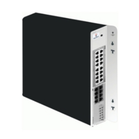
Dimension: H = 66 mm; W = 442 mm; D = 400 mm. Weight: 6 kg. 2.2.3 OmniPCX Office RCE Medium 56 ports. 1 CPU slot 5 general-purpose slots. Energy consumption: 1,2 A (230 V) / 2,3 A (110 V) - 120 W. -
Page 19: Installation
Installation 2.3.1 Overview This hardware must be installed on the customer's site, by a qualified installer, in... -
Page 20: Equipment
Equipment 2.4.1 Boards and Options The following table lists the boards available on Alcatel-Lucent OmniPCX Office Communication Server (S, M or L racks) OmniPCX Office RCE Small, Medium, Large Board Function Optional boards Connections APA2 2, 4 or 8 analog trunk line inter-... -
Page 21: Detailed Description
Connections MIX244 0, 2 or 4 T0 basic accesses + 4 ISDN network, analog Z ter- MIX248 or 8 UA interfaces + 4 or 8 Z in- minals and Alcatel-Lucent 9 MIX284 terfaces series or Alcatel Reflexes MIX484 stations MIX448... - Page 22 Chapter As of R8.0, the PowerCPU board performs the CPU functions of an OmniPCX Office system. 2.4.2.1.1 Function of the LEDs Name Color Function Green CPU functioning LED (flashing) POWER Red/Green Mains operation: steady green LED Battery operation: steady yellow LED...
- Page 23 Board used for connecting up digital terminals or DECT 4070 IO/EO base stations. The UAI16-1 board is used to power terminals connected to the 16 interfaces remotely from an EPS48 external power supply connected to interface 1 via an external adapter cable (splitter). Caution: Only use EPS48 power supplies and the splitters provided.
- Page 24 2.4.2.7 PRA Boards This board provides 1 primary access for connecting the Alcatel-Lucent OmniPCX Office Communication Server system to the ISDN digital public network or to private networks: PRA -T2, DASS2, DLT2 : 30 x 64-Kbps B-channels + 1 x 64-Kbps D-channel; 2048 Kbps.
- Page 25 T2 Name T1 Name Function BUSY BUSY B-channels busy (red LED lights up if at least 1 B-channel is busy) RAI (ATD) Remote frame alarm (red LED lights up on alarm) AIS (SIA2M) Too many "1's in the 2-Mbit binary train (red LED lights up on alarm) NOS (MS) NSIG Absence of 2-Mbit signal (red LED lights up on alarm)
- Page 26 Chapter Each category-5 RJ45 connector has 2 green LEDs: Left LED = link status and activity: • off: link disconnected • on: link connected • blinking: link active Right LED = full duplex/collision: • off: Half Duplex • on: Full Duplex •...
- Page 27 CPU PowerCPU board , according to the platform used Daughter Boards OmniPCX Office RCE Compact OmniPCX Office RCE Small, Medium, Large ARMADA HSL1 HSL2 AFU, AFU-1 SATA HARD DISK...
- Page 28 Chapter Figure 2.22: Example of CPU with SATA Hard Disk Daughter Boards on PowerCPU 2.4.2.14 Provision By Platform 2.4.2.14.1 OmniPCX Office RCE Compact Board MIX Slot CPU Slot PowerCPU Mandatory MIX x/y/z AMIX-1 x/y/z Mini-MIX 2.4.2.14.2 OmniPCX Office RCE Small...
- Page 29 SLI16, SLI16-1 PRA-T2, PRA-T1, DASS2, DLT2, T1-CAS, PCM R2 APA4, APA8 DDI2, DD14 BRA2, BRA4, BRA8 LANX8, LANX16, LANX16-1, LANX8-2, LANX16-2 2.4.2.14.3 OmniPCX Office RCE Medium Boards Slots 1-2-3-4-5 CPU Slot PowerCPU Mandatory MIX x/y/z AMIX-1 x/y/z UAI4, UAI8, UAI16, UAI16-1...
- Page 30 Chapter Caution 1: The VoIP4-1, VoIP8-1 and VoIP16 boards implemented on a CPU board consume a hardware re- source used for slot 8 of the module. In that case, it is impossible to add a board other than a LANXxx board in slot 8. Boards Slot 1 Slots 2-3-4...
-
Page 31: Software Licence Management
3.1.1 SOFTWARE LICENCE MANAGEMENT On an Alcatel-Lucent OmniPCX Office Communication Server several types of devices may be connected, several services may be offered and several applications may run. The purpose of the feature “Software Licence Management” is to define for a given system (i.e. -
Page 32: Voice Services Available In "Limited" Mode
Chapter the CTI Software key for the CTI functions The software key corresponds to a text file where the name is the CPU hardware number with the .MSL (MAIN key) or .CSL (CTI key) extension. Example: file 000068DA.msl and 000068DA.csl for main CPU no. 000068DA. Each system needs the Main and CTI Software keys even if no CTI application is used on the system. -
Page 33: Software Key Change
Software key -> Hardware serial number Send this serial number and the function levels required to Alcatel-Lucent Enterprise Load the key file Main.msl or CTI.csl from the Alcatel-Lucent Business Partner Internet site (this file can also be downloaded by the manufacturer) Downloading a new software key: •... - Page 34 Chapter The following table lists the functions controlled by the "Main" software key, the "limited" mode values and the configuration modularity. Controlled services Relevant Values in lim- Modular- Hardware ex- software ited mode tension version STANDARD TELEPHONY Number of digital sets According to selected model Number of analog sets...
- Page 35 Controlled services Relevant Values in lim- Modular- Hardware ex- software ited mode tension version GREETING Number of messages (16") ON-HOLD MUSIC Duration (minutes) MULTIPLE AUTOMATED ATTENDANT Number of tree structures: From R6.0 closed open 1 license for 1 tree structure 1 license for 5 tree structures "ON DEMAND"...
-
Page 36: Services Controlled By The "Cti" Software Key
Not controlled by the system INTEGRATED TAPI 2.0 *** Number of sessions 25 (R1) 75/200 * 0 (from R2) Number of monitors 250 (R1) 250/500 ** 0 (from R2) Features None Alcatel-Lucent OmniPCX Office Communication Server CALL CENTER Number of sessions 28/200 *... - Page 37 Number of monitors 250/500 ** Features None CSTA DESKTOP CLIENT Number of sessions 28/200 * Number of monitors 250/500 ** Features None CENTRAL SERVICES Number of sessions 28/200 * Number of monitors 250/500 ** Features None CSTA (ALL FEATURES) Number of sessions 28/200 * Number of monitors 250/500 **...
- Page 38 Chapter ** The maximum number of monitors of all kinds at any one time is 250 on ASPEN and 500 on PIII. *** In R1, this service is always present in the CTI software key. Only two monitors per session are allowed.
-
Page 39: Presentation
Presentation 4.1.1 Location of Unit The Alcatel-Lucent OmniPCX Office Communication Server unit can be installed in three ways: 1. Fixed directly to the wall: • A kit is available for wall-mounting Rack 1 OmniPCX Office RCE Small Rack 2 OmniPCX Office RCE Medium... - Page 40 Chapter 4.1.1.2 Mounting in the 19" Rack...
-
Page 41: Environment
The maximum static load (given by the manufacturer) of the 19" rack is greater than the overall weight of the equipment mounted or to be mounted in the rack. Moreover, the weight of the equipment must be evenly distributed between the brackets. If mounting the Alcatel-Lucent OmniPCX Office Communication Server module platform... -
Page 42: Connections And Cabling
4.2.1.1 Output Connectors All outputs are made using Female RJ45 connectors. Remark 1: the CPU-2 and MIX boards used for Alcatel-Lucent OmniPCX Office Compact Edition have the same characteristics as those used by Alcatel-Lucent OmniPCX Office Communication Server. 4.2.1.1.1 PowerCPU... - Page 43 CenRg CenRG SLI1/SLI2 Ground +12 V CenRG Ground +12 V CenRg A Ground CONFIG RMTRES Ground MODULE1 ISDN MODULE2 ISDN Audio In Audio Audio Audio Audio AUDIO Audio In A Alarm A Alarm B Ctrl A Out A Out B Ctrl B DoorPhB DoorPhA...
- Page 44 Chapter RJ45 pin 1 to 16 1 to 16: connecting analog Z terminals. 4.2.1.1.3 UAI Board RJ45 pin 1 to 16 (UAI) 1 to 16: connection of digital terminals or DECT 4070 IO/EO base stations. 4.2.1.1.4 UAI-1 Board RJ45 pin 2 to 16 1 : connection of an EPS48 external power supply + connection of digital terminals or DECT 4070 IO/EO base stations.
- Page 45 RJ45 pin Ports 1 to 14 GE1, GE2 TR0+ TR0- TR1+ TR2+ TR2- TR1- TR3+ TR3- Ports 1 to 14: 10/100 BT ports. GE1, GE2: 10/100/1000 BT ports. 4.2.1.1.9 APA Board RJ45 pin Output 1 ZSETB ZSETA LB-Ring LA-Tip Outputs 2 to 8 LB-Ring LA-Tip 1 : connection of network line 1, SLI interface and callback terminal...
- Page 46 Chapter 4.2.1.4 Connecting Terminals 4.2.1.4.1 Connection of Digital Terminals The terminals are equipped with a cable and a self-acting switch that plugs into the wall socket. Each terminal is connected up by a pair of 0.5 or 0.6 mm diameter wires. System - digital terminal distances: 0.5 mm SYT type cable: 800 m (station without option) or 600 m (station with S0 or Z option).
- Page 47 Connection with External Power Supply A splitter allows the separation of the UA peripheral connection and the EPS48 external power supply. 4.2.1.4.2 Connecting Analog Terminals The terminals are equipped with a cable and a self-acting switch that plugs into the wall socket.
- Page 48 Connection to the Public Network 4.2.1.5.1 Digital Public Network via T0 Access (or DLT0 Private Network) The Alcatel-Lucent OmniPCX Office Communication Server system can be installed near the digital network termination or at a certain distance (up to 350 m), as required.
- Page 49 The ISDN-EFM box must be installed as close as possible to the system (3 m maximum). All the box connections are made with straight RJ45-RJ45 cables. Output connector functions: BRA: connection of T0 access to be forwarded. NT: Connection of ISDN network termination. S0: connection of forwarding S0 station.
- Page 50 Chapter 4.2.1.5.2 Digital Public Network by T1 or T2 Access The diagram below shows a PRA-T2 board, but is equally applicable for a PRA-T1 board. 4-12...
- Page 51 The PRA board is connected to a digital line termination (DLT) by 2 symmetrical twisted pairs. Cable impedance: 120 Ohms +/- 20% between 200kHz and 1MHz; 120 Ohms +/- 10% at 1 MHz. Remark: We recommend using an L120-series cable (or the L204 equivalent). The distance T1-DLT or T2-DLT is limited by the amount of loss between the DLT and T1/T2, which must not exceed 6 dB at 1024 kHz.
- Page 52 Chapter 4.2.1.5.4 Analog Public Network - Direct Dialing In. 4.2.1.6 Lan Connection The LANX8/LANX16 board is used to connect servers, PCs, IP terminals and external switches. 4-14...
- Page 53 Category 5 cable, FTP or STP, impedance 100 Ohms: maximum length 100 m. 4.2.1.7 Connecting Auxiliary Equipment All auxiliary equipment is connected via the AUDIO , AU DIO-OUT and DOORPHONE connectors of the CPUe-1, CPUe-2, CPU-1, CPU-2, and CPU-3 PowerCPU board 4.2.1.7.1 Connecting a Please-Wait Message Player This is connected via the AUDCTRL output (control contact open when idle) and the AUDIN...
- Page 54 Chapter Audio Input Characteristics: Input impedance : 600 Ohms Fuse Characteristics: Max. power : 10 W Max. voltage : 60 V Max. current : 500 mA The contacts of the alarm and doorphone controls have the same electrical characteristics as those indicated above. 4.2.1.7.2 Connecting a Background Music Tuner This is connected via the AUDIN input of the AUDIO connector.
- Page 55 Input impedance : 600 Ohms Input level: access + 4.7 dBr or + 15 dBr 4.2.1.7.3 Connecting an Alarm The alarm is activated in the event of a false stopping of the system. It is connected via the ALARM output (control contact closed when idle) of the AUDIO connector.
- Page 56 Chapter The general ringer is connected via the CENRG output of the AU DIO-OUT connector. 4.2.1.7.6 Connecting a Doorphone 2 doorphone types are available, depending on the operating mode used: Type A: relay-controlled doorphones (e.g. NPTT) Type B: doorphones controlled by MF Q23 signals requiring an SLI interface (e.g. TELEMINI and UNIVERSAL DOORPHONE) The doorphone interface comprises an intercom and an optional latch powered by the mains supply through a SELV (Safety Extra Low Voltage) transformer.
- Page 57 A single doorphone with doorstrike may be connected to the system. The system also allows for the connection of 2 doorphones without latch. Connecting a Telemini and Universal Doorphone These doorphones require the use of a Z station interface. Several of these doorphones can be connected to the system; the limit is determined by the maximum number of analog stations the system can support.
-
Page 58: Power Supply
4.3.1.2 Battery Implementation Alcatel-Lucent OmniPCX Office Communication Server is supplied with one or more integrated batteries; they are mounted and fixed with a solid bar on the rear plate. Caution:... -
Page 59: Battery Replacement
OmniPCX Office RCE Compact ) can be powered by external batteries. The use of external batteries is an alternative to the UPS solution. It ensures that the Alcatel-Lucent OmniPCX Office Communication Server systems are backed up. This solution offers a maximum autonomy of 8 hours. - Page 60 Compact Edition OmniPCX Office RCE Compact Note: The external battery units for Alcatel-Lucent OmniPCX Office Communication Server units L, M and S OmniPCX Office RCE Small, Medium, Large platforms are pre-wired and delivered with inter-battery connectors. In addition, you will need:...
- Page 61 You will have to choose the appropriate preparation procedure, according to whether you have a rack or stack version of the external battery unit. The connection procedure is the same for Alcatel-Lucent OmniPCX Office Communication Server M OmniPCX Office RCE Medium...
- Page 62 Chapter Figure 4.25: Wiring Diagram of a 36V External Battery Rack Unit (1 or 2x7Ah in parallel) This type of unit is only used for an Alcatel-Lucent OmniPCX Office Communication Server L OmniPCX Office RCE Large model platform Procedure Position the 12V - 7Ah external batteries in the battery rack unit (maximum 3 batteries for an...
- Page 63 black) and that there is no cable connected to the J1 connector (see the figure below). 2. Open the unit by removing the four screws (ST3.5x32) with a screwdriver (Phillips PH2). 3. Insert the batteries in the open unit as follows (also see the figure below): a.
- Page 64 7. Stick a label on the unit stating the date of the installation and the number of batteries installed. Procedure for 36 V stack version (for OmniPCX Office RCE Large systems platforms The 12 V stack version of the external battery unit can...
- Page 65 be connected in parallel to obtain the autonomy achieved with six batteries. 1. Ensure that the ON/OFF switch on the external battery unit is set to the OFF position (0 or black) and that there is no cable connected to the unit (see the figure below). 2.
- Page 66 Mate-N-Lok 3-terminal connector must be connected to the principal unit and its Mate-N-Lok 2-terminal connector must be connected to the extension unit. Installation of External Batteries for the OmniPCX Office RCE Medium OmniPCX Office RCE Large Units...
- Page 67 1. Stop the Alcatel-Lucent OmniPCX Office Communication Server system, and remove the power supply cord from the system platform side. Disconnect the power supply cable on the system platform side before handling the power supply. This operation disconnects the mains supply and the internal battery.
- Page 68 L OmniPCX Office RCE Large platform 11. Connect the cable (with J1 connector) between the Alcatel-Lucent OmniPCX Office Communication Server system and the external unit. 12. Set the ON/OFF switch on the external battery unit to the ON position (I or red).
- Page 69 7. Put the upper cover back in place. 8. Connect the cable (with J1 connector) between the Alcatel-Lucent OmniPCX Office Communication Server system and the external unit. 9. Set the ON/OFF switch on the external battery unit to the ON position (I or red).
- Page 70 4.3.1.3.5 Installation of External Batteries for the OmniPCX Office RCE Compact Platform You must first prepare the external battery unit for use and then connect this unit to the Alcatel-Lucent OmniPCX Office Compact Edition OmniPCX Office RCE Compact unit platform .
- Page 71 3. Connect the negative (black) terminals of the batteries as described below (and shown in the figure below). a. Connect the middle connector of the black wire to the negative (black) terminal of battery B1. b. If required, connect the end connector of the black wire to the negative (black) terminal of battery B2.
- Page 72 Connecting to the OmniPCX Office RCE Compact Platform 1. Switch off the Alcatel-Lucent OmniPCX Office Communication Server system and then: a. Unplug the power cable from the mains socket. b. Disconnect the mains adapter from the Alcatel-Lucent OmniPCX Office Compact...
-
Page 73: Connecting A Ups
It is connected via the mains socket at the rear of the unit platform UPS Power: use the mains cable provided with the Alcatel-Lucent OmniPCX Office Communication Server module. UPS Connection - module: use the cable supplied with the UPS For an installation using 3 Alcatel-Lucent OmniPCX Office Communication Server modules, 2 UPSs are required: one feeds two of the modules, the other feeds the third module. - Page 74 Chapter 4.3.1.5.1 OmniPCX Office RCE Small, Medium, Large The connection can be made using electrical installations of the following type: TT (local ground for each piece of equipment). TN (common ground for all equipment). IT with inter-phase voltage of 230 V; only possible in Norway.
-
Page 75: Series Sets
This module presents all the actions required for commissioning: The Alcatel-Lucent IP Touch 4018 Phone set The Alcatel-Lucent IP Touch 4018 phone Extended Edition set The commissioning of Alcatel-Lucent IP Touch 4018 Phone and Alcatel-Lucent IP Touch 4018 phone Extended Edition sets is identical. 4-37... - Page 76 Chapter The following figure illustrates the connectors on the base of the Alcatel-Lucent IP Touch 4018 Phone and Alcatel-Lucent IP Touch 4018 phone Extended Edition sets. Figure 4.40: Alcatel-Lucent IP Touch 4018 Phone and Alcatel-Lucent IP Touch 4018 phone Extended Edition connectors 4.4.1.1.2 Commissioning the set...
- Page 77 To connect the set to the LAN: 1. Turn the set over so that you can see its base. 2. Plug the RJ45 cable into the set's LAN connector. 3. Connect the RJ45 cable to the LAN itself. Connecting power supply The set can be supplied from two possible power sources: An AC/DC external adapter which is a 42V power supply A female jack is used to connect the power adapter.
- Page 78 Chapter You do not have a DHCP Static mode Refer to table: Initialization server procedure Obtain from your network administrator: • An IP address for the IP Touch set • The subnetwork mask • The router address • The TFTP server ad- dress (master VoIP board address) Initializing the IP Touch set...
- Page 79 Static 1. Connect the power supply. 2. Before initialization phase 5 starts, press i, then the # key. The Main menu appears. 3. From the Main menu, choose IP Parameters. The IP Parameters menu appears. 4. Choose Static and press the OK key. 5.
-
Page 80: Ip Touch 4028/4038/4068 Phone
2. Plug the set into a connector at its new location. 4.4.1.1.3 The Alcatel-Lucent IP Touch 4008 Phone set The Alcatel-Lucent IP Touch 4008 Phone is a cost reduction of the Alcatel-Lucent IP Touch 4018 Phone with a new transceiver and a new LAN switch. - Page 81 Figure 4.41: Alcatel-Lucent IP Touch 4028 Phone, Alcatel-Lucent IP Touch 4038 Phone and Alcatel-Lucent IP Touch 4068 Phone connectors 4.4.2.1.2 Commissioning the sets This section describes how to: Connect the sets Initialize the sets Connect optional equipment Program keys Prerequisites None.
- Page 82 Chapter To connect the set to the LAN: 1. Turn the set over so that you can see its base. 2. Plug the RJ45 cable into the set's LAN connector. 3. Connect the RJ45 cable to the LAN itself. Connecting power supply The set can be supplied from two possible power sources: An AC/DC external adapter which is a 42V power supply A female jack is used to connect the power adapter.
- Page 83 You do not have a DHCP Static mode Refer to table: Initialization server procedure Obtain from your network administrator: • An IP address for the IP Touch set • The subnetwork mask • The router address • The TFTP server ad- dress (master VoIP board address) Note:...
- Page 84 Connecting an Add-On module to the sets Add-On Modules (AOMs) can be connected to the Alcatel-Lucent IP Touch 4028 Phone, Alcatel-Lucent IP Touch 4038 Phone and Alcatel-Lucent IP Touch 4068 Phone sets. They are added to the right side of the set.
- Page 85 Prerequisites None. Rules and restrictions The following rules apply to the use of Add-On Modules with the Alcatel-Lucent IP Touch 4028 Phone, Alcatel-Lucent IP Touch 4038 Phone and Alcatel-Lucent IP Touch 4068 Phone sets: A maximum of three Add-On Modules of the types AOM10 and AOM40 can be connected to each set, providing up to 120 additional keys.
- Page 86 Chapter The 3.5 mm female jack can receive an external station speaker jack. In order to take the external station speaker into account, the set customization for the jack has to be set to “Loudspeaker”. Prerequisites None. Connecting an external station speaker To connect an external station speaker, plug the external station speaker jack into the associated connector on the side of the set.
-
Page 87: Series Sets
2. Plug the set into a connector at its new location. 9 Series Sets 4.5.1 4019 Digital Phone 4.5.1.1 Commissioning 4.5.1.1.1 Overview This module presents all the actions required for commissioning the Alcatel-Lucent 4019 Digital Phone set. The following figure illustrates the connectors on the base of the set. 4-49... - Page 88 Chapter Figure 4.42: Alcatel-Lucent 4019 Digital Phone connectors 4.5.1.1.2 Commissioning the set This section describes how to: Connect the set Program keys Prerequisites None. Connecting the set This section describes how to connect the set to the telephone system. Prerequisites None.
-
Page 89: 4029/4039 Digital Phone
4.5.2.1 Commissioning 4.5.2.1.1 Overview This module presents all the actions required for commissioning the Alcatel-Lucent 4029 Digital Phone and Alcatel-Lucent 4039 Digital Phone sets. The following figure illustrates the connectors on the base of each set. Figure 4.43: Alcatel-Lucent 4029 Digital Phone and Alcatel-Lucent 4039 Digital Phone connectors 4.5.2.1.2 Commissioning the sets... - Page 90 Add-On Modules (AOMs) can be connected to the Alcatel-Lucent 4029 Digital Phone and Alcatel-Lucent 4039 Digital Phone sets. They are added to the right side of the set. Three types of Add-On Module exist and provide keys associated with icons:...
- Page 91 42 additional keys. Add-On Modules of types AOM10 and AOM40 can be used on the same set, but a Smart Display Module cannot be used in conjunction with an AOM10 or AOM40. If an AOM10 is used with other Add-On Modules, it must be connected as the last module on the far right of the set.
-
Page 92: V24/Cti Interface Module
The desired name is associated with the key. Note: As of release 6.0 of Alcatel-Lucent OmniPCX Office Communication Server, it is possible to use Uni- code - Chinese and Cyrillic - characters. It is at this step that it becomes active, if used. For more in- formation about IME, refer to the section Operation - Input Method Editor in this chapter. -
Page 93: Hardware Description
The V24/CTI Interface Module allows a Data Terminal Equipment (DTE) to be connected to the OmniPCX Office, via a UA link, by means of an RS232 serial link (CTI port) or a V24 link. The V24/CTI Interface Module can be used alone or combined with an Alcatel-Lucent 9 series set. -
Page 94: Hardware Configuration
Chapter 4.6.1.2.2 ECM EN55022: Limits and methods of measurement of radio interference characteristics of information technology equipment EN55024: Limits and methods of measurement of immunity characteristics of information technology equipment FCC part15: US requirements 4.6.1.2.3 V24 & CTI CCITT Rec.: V24,V28, V25bis, V54, V110 Hayes protocols ECMA 102: Attachment requirements for pan-European approval for connection to PSTN of TE (excluding TE supporting the voice telephony service) in which network addressing,... -
Page 95: External Connections
4.6.2.2 Jumpers The jumper in a gray background is factory installed. To configure the V24/CTI Interface Module, open the device with the 2 screws located under the module. If the jumper is positioned for "stand-alone" operation, an associated set cannot work. If the jumper is positioned for "associated UA set"... - Page 96 Chapter The V24/CTI Interface Module is connected as follows: Figure 4.47: V24/CTI Interface Module Connection The V24/CTI Interface Module is connected to: 1. The digital set 3 m maximum length ( RJ11/RJ11 cable) 2. The PCX via a wall socket and a distributor frame 3.
-
Page 97: Ap Interface Module
2. V24 SUBD9 connector 3. CTI SUBD9 connector Figure 4.49: Connector Details RS 232 port (V24): Signal Description Data Carrier Detect. Transmit data. Received data. Data Terminal Ready. Protective ground. Data Set Ready. Request To Send. Clear To Send. Ringing Indicator. CTI port: Signal Description... -
Page 98: Compliant Standards
Communication Server via a UA link. Figure 4.50: Example of Configuration with an AP Interface Module AP Interface Module can be used alone or combined with an Alcatel-Lucent 9 series set. Note: The AP Interface Module is also compatible with Alcatel Reflexes sets. -
Page 99: Hardware Configuration
ETS 300 439: Business TeleCommunications (BTC); Transmission characteristics of digital Private Branch eXchanges (PBXs) TBR21: Attachment requirements for pan-European approval for connection to PSTN of TE (excluding TE supporting the voice telephony service) in which network addressing, if provided, is by means of DTMF signalling 4.7.1.2.4 Environment Classes ETS 300 019: Environmental conditions and tests for telecommunication equipment: •... -
Page 100: External Connections
Connecting AP Interface Module Figure 4.53: AP Interface Module Connections The AP Interface Module is connected to: 1. Digital set ( RJ11/RJ11 cable). 3 m maximum length 2. Alcatel-Lucent OmniPCX Office Communication Server via a wall socket and a distributor 4-62... - Page 101 frame. Connect an AP module is identical to connect a digital set. Maxinum length between AP module and PCX depends on cable quality. For example: • LY 0.5 mm cable: up to 800 m • Ref 278 0.6 mm cable: up to 1200 m 3.
-
Page 102: S0 Interface Module
Alcatel-Lucent OmniPCX Office Communication Server via a UA link. This bus allows S0 terminals (S0 sets, PCs equipped with an S0 interface, Fax G4, modem, etc.) to be connected. The S0 Interface Module can be used alone or combined with an Alcatel-Lucent 9 series set. 4-64... - Page 103 Note: The S0 Interface Module is also compatible with Alcatel Reflexes sets Figure 4.56: Example of Configuration with an S0 Interface Module The S0 module provides an S0 bus supplying power. An external power supply (230V AC/48V DC adapter) is required. There are two possible operating modes on the S0 bus: Non permanent layer: layer 1 must be set up by the calling end (PCX or terminal) at the start of each call;...
-
Page 104: Hardware Configuration
Chapter EN55022: Limits and methods of measurement of radio interference characteristics of information technology equipment EN55024: Limits and methods of measurement of immunity characteristics of information technology equipment FCC part15: US requirements 4.8.1.2.3 ISDN ETS 300 012: Basic user-network interface layer 1 specification and test principles TBR3: Attachment requirements for terminal equipment to connect to an ISDN using ISDN basic access ETS 300 047: Basic access-safety and protection... -
Page 105: External Connections
4.8.2.2 Jumper The jumper in a gray background is factory installed. To configure the S0 Interface Module, open the device with the 2 screws, located under the module. If the jumper is positioned for "stand-alone" operation, an associated set cannot work. If the jumper is positioned for "associated digital set"... - Page 106 The S0 module is connected to: 1. A digital set (optional), via an RJ11/RJ11 cable of a 3 m maximum length 2. The Alcatel-Lucent OmniPCX Office Communication Server, via a wall socket and a distributor frame Connecting an S0 module is identical to connecting a digital set.
- Page 107 Figure 4.60: Rear Panel Details 1. RJ11 socket for UA line 2. RJ45 socket for S0 bus 3. Power supply socket Figure 4.61: Socket Details PCX and digital set socket: Description Not used External Ringing 1 UA line 1 UA line 2 External Ringing 2 Not used S0 bus RJ45 socket:...
-
Page 108: Intelligent Base Stations
4.9.1.1 CONNECTION The Alcatel-Lucent 4070 IO is designed for internal installation in the building, while the Alcatel-Lucent 4070 EO is designed for external installation. The 4070 EO IBS comes in a plastic box and is protected against temperature variation. - Page 109 NUMBER OF USEFUL BASE STATIONS Any radio signal is subject to various propagation phenomena: attenuation, reflection and diffraction. These phenomena are related to the environment of the Alcatel-Lucent 4070 IO/EO, and affect the radio performance of the system. The effects can improve or deteriorate wave propagation.
- Page 110 Take as an example a building with a metallic structure. A radio wave will tend to be subject to many reflections which will consequently degrade system performance. Moreover, the range of an Alcatel-Lucent 4070 IO/EO is very dependent on the amount of attenuation subjected to the radio wave across various zones.
- Page 111 The ARI number identifies each OmniPCX Office. Each OmniPCX Office has an identical default ARI number. When you install a new OmniPCX Office, you have to change the default ARI number. You can only keep the first digit, which is "1" and which means "ARI type B".
- Page 112 The Line length is the cable length used to plug the IBS to the system (distance between the IBS and OmniPCX Office). It enables the system to add a delay in signal and to avoid a shift in clock signal that creates a reset of the IBS.
- Page 113 The IBS is fitted with a software device that analyses audio signals and eliminates echo and noises. This device is activated by default. When an IBS is deployed in a noisy environment, a lot of signals, including Speech ones, are eliminated while in Conversation state.
- Page 114 Chapter Once the IBS finishes the downloading, the system starts the initialization. The system synchronizes the signals of the IBSs so that handovers are possible. The system selects the T0, T2, or CPU main board clock as the source. Then the system sends the following data: Fixed part capabilities (Full slot, frequency control, page repetition, setup on dummy, basic A field setup): value sent = 0x007910 Line length: Short line...
- Page 115 1902.528 1903.392 Note 2: By default, all frequencies used Value sent to IBS: 0x3FF 0000 0011 1111 1111 table 4.36: RF Band Latam Channel TX Freq RX Freq 1928.448 1929.312 1926.720 1927.584 1924.992 1924.992 1923.264 1923.264 1921.536 1921.536 1919.808 1919.808 1918.060 1918.060 1916.352...
-
Page 116: Safety Rules
Alcatel-Lucent 4070 IO/EO. 4.9.2.1.1 Conditions for using lightning protection: Protection of Alcatel-Lucent 4070 IO/EO against lightning should be used when they: - are less than 1.5 m from a wall more than 2 m below the antenna. - Page 117 4.9.2.3.2 Layout technique For structures with a number of floors, different solutions can be envisaged as a function of: the coverage obtained at each level. the position of the Alcatel-Lucent 4070 IO/EO (higher or lower level). Installation examples 4-79...
- Page 118 Chapter Square zone Rectangular zone Example 1: square building Example 2: rectangular building floor floor floor floor It is possible to alter the number of base stations used from one floor to another for this type of building. The technique used is overlapping the location of base stations from one level to another. This technique can be used for alternate floors if the coverage of a level can be achieved from an adjacent level.
-
Page 119: Pimphony
PIMphony 4.10.1 Overview Alcatel-Lucent PIMphony is a personal productivity tool that connects your phone terminal (dedicated, analog or DECT wireless set) with your computer, providing enhanced usage of your telephone. PIMphony IP is an IP phone that provides the same level of features as PIMphony associated with an actual terminal. -
Page 120: Additional Information
Chapter Alcatel-Lucent PIMphony also provides tight integration with the most popular PIMs (Personal Information Managers) on the market, enabling them for Computer Telephony. Note: For information and details concerning Alcatel-Lucent PIMphony installation, refer to the Installation Manual section in the PIMphony Online Help. -
Page 121: Reflexes Terminals
Alcatel-Lucent OmniPCX Office Advanced Edition CS Alcatel-Lucent OmniPCX Office Communication Server with Hard Disk platforms 200 maximum for Alcatel-Lucent OmniPCX Office Premium Edition CS platforms Simultaneous connected users in HTTPS: 10 maximum for Alcatel-Lucent OmniPCX Office Advanced Edition CS Alcatel-Lucent... - Page 122 Chapter option) 278 type 1.6 mm cable: 1200 m (terminal without option) or 850 m (station with S0 or Z option) 4.11.1.2 Premium AND Advanced Reflexes TERMINALS 4.11.1.2.1 Attaching the line cable: Turn the terminal Remove the panel at the rear of the terminal (pull it towards the interior of the terminal and then pull it out).
- Page 123 Attach the terminal using the two lugs: introduce the lugs into the holes previously occupied by the feet (left foot and hole intended for this purpose for Advanced Reflexes terminals). Stabilize the mounting by clipping the foot into the base of the terminal. 4.11.1.2.4 Mounting optional modules: Turn the terminal Remove the panel situated at the rear of the terminal.
- Page 124 Connect the unit to the terminal. Join the module to the set using the metallic strip and the 4 screws provided in the kit 4.11.1.3 Alcatel-Lucent First AND Easy Reflexes TERMINALS 4.11.1.3.1 Attaching the line cable: Turn the terminal Plug in the line cable(connector ) and position it as shown in the illustration.
- Page 125 Plug in the handset cable (connector ) into the guide intended for this purpose. 4.11.1.3.2 Wall mounted Preparing the terminal Turn the terminal Unscrew A and remove the metal plate. Slide this plate up the lower groove and secure it with screw B. Remove the handset hang-up lug by turning screw C through half a turn.
-
Page 126: Extending Your Installation
Chapter For Alcatel-Lucent First and Easy Reflexes terminals, the optional module is external to the terminal; this module can be placed on a table or wall mounted. The installation simply involves connection between the terminal, the module and the wall sacket. - Page 127 Permanent replacement The maximum quantity of data from the initial set is transferred to the replacement. Data not transferred are deleted. Characteristics preserved during temporary or permanent set substitution Rights (restricted features) Barring level Metering profile Messages and last caller repertories Destination set for metering reminder, forwarding and/or monitoring Set belonging to a hunting group and/or a Manager-Secretary relation Appointment reminder...
- Page 128 Chapter modules. Note: It is possible to replace a Reflexes set with an Alcatel-Lucent 9 series set. It is not possible to replace an Alcatel-Lucent 9 series set with a Reflexes set. 4.12.1.1.2 IP Touch set replacement You can replace your IP Touch terminal by connecting a terminal of the same family only, into your phone socket.
- Page 129 The set is recognized as soon as it has been plugged into the socket. 4.12.1.1.5 Using a Multi Reflexes 4099 hub Multi Reflexes 4099 option (also called Multiple UA hub) connects up to 3 Alcatel-Lucent 9 series or Alcatel Reflexes terminals to an Alcatel-Lucent OmniPCX Office Communication Server using just one UA link.
- Page 130 Chapter Interface classification UA link: TBTS Hub/Alcatel-Lucent 9 series or Alcatel Reflexes 1 to 3 : TBTS Maximum distances between Alcatel-Lucent OmniPCX Office Communication Server and sets 0,4 mm cable: 325 m 0,5 mm cable: 505 m 0.6 mm cable: 730 m Cables of 3 m and 10 m are available for connecting the sets to the hub.
- Page 131 Figure 4.81: PATA Hard Disk Connection Figure 4.82: SATA Hard Disk Connection During installation, always take anti-static precautions (wristband, heelpiece, etc.) before handling the hard disk. Any degradation caused by electrostatic discharges will reduce the life of the disk. Handle the hard disk by its sides and do not touch the connector. When going into stand-by mode, wait for the red Power LED to stop flashing before you remove the module's PowerCPU...
- Page 132 Chapter It is possible to add one or two modules to the basic module. 4.12.1.4.1 Fitting a Module Expansion The CPU slot of the add on module expansion must be fitted with a PowerMEX board with an HSL1 daughter board. Fit the PowerCPU board of the main module with an HSL daughter board.
- Page 133 RJ45 pin MAIN: MAIN: HSL to basic module. 4.12.1.4.3 Role of the # key Name Color Feature POWER Red/Green Mains operation: steady green led Battery operation: steady yellow led Standy: steady red LED Red/Green Both fans functioning: steady green led 1 or both fans down: steady red led 4.12.1.4.4 Adding a third module Replace the HSL1 board of the...
- Page 134 8. Use OMC to restore the previously saved configuration data. Migration to R8.x OmniPCX Office RCE Compact The following sequence is used to migrate to R8.x OmniPCX Office RCE Compact. 1. Use the OMC to save configuration data 2. Use LOLA to save customer data from the current main CPU...
- Page 135 5. Plug the PowerCPU. 6. Use LOLA to install the R8.x. 7. Use LOLA to restore the previously saved customer data. Configuration After the hardware upgrade and migration, use the OMC configuration procedures to configure the Alcatel-Lucent OmniPCX Office Communication Server . 4-97...
- Page 136 Chapter 4-98...
-
Page 137: Detailed Description
Detailed description 5.1.1.1 DEFAULT CONFIGURATION 5.1.1.1.1 Alcatel-Lucent 8 series and Alcatel-Lucent 9 series station profiles Alcatel-Lucent IP Touch 4038 Phone, Alcatel-Lucent IP Touch 4068 Phone and Alcatel-Lucent 4039 Digital Phone sets Each of these sets has 2 programmable keys (F1/F2) and 40 virtual add-on keys. Their default... - Page 138 Chapter Figure 5.1: Virtual Key Functions for Operator Sets in KeySystem mode...
- Page 139 Figure 5.2: Virtual Key Functions for Manager/Assistant/Normal sets in KeySystem Mode...
- Page 140 Chapter Figure 5.3: Virtual Key Functions for Attendant sets in KeySystem Mode (with no Physical Add-on)
- Page 141 Figure 5.4: Virtual and Physical Add-on Key Functions for Attendant Sets in KeySystem mode...
- Page 142 Chapter Figure 5.5: [US only] Virtual Key Functions for Operator Sets in KeySystem Mode...
- Page 143 Figure 5.6: [US only] Virtual Key Functions for Manager/Assistant Sets in KeySystem Mode...
- Page 144 Chapter Figure 5.7: [US only] Virtual Key Functions for Normal Sets in KeySystem Mode...
- Page 145 Figure 5.8: Virtual Key Functions for Operator/Manager/Assistant/Normal Sets in PABX Mode...
- Page 146 Chapter Figure 5.9: [US only] Virtual Key Functions for Operator Sets in PABX Mode 5-10...
- Page 147 Figure 5.10: [US only] Virtual Key Functions for Manager/Assistant Sets in PABX Mode 5-11...
- Page 148 The default functions of these keys are the same as for the sets detailed in § Alcatel-Lucent IP Touch 4038 Phone, Alcatel-Lucent IP Touch 4068 Phone and Alcatel-Lucent 4039 Digital Phone sets . However, in this case the virtual keys are selected using 4 physical buttons, 2 on each side of the set's display, as shown below.
- Page 149 There are 10 pages of virtual keys (the pages can be scrolled through using the up/down buttons of the set's 4-way navigator), with 4 virtual keys on each page. Alcatel-Lucent IP Touch 4018 Phone and Alcatel-Lucent 4019 Digital Phone sets Each of these sets has 6 programmable keys which have the default functions indicated below.
- Page 150 Chapter 5-14...
-
Page 151: System Startup From A Phone Set
Follow this start-up session to enter the data required to operate the system. The procedures below show the Alcatel-Lucent IP Touch 4068 Phone interface, but the menus are the same using the Alcatel-Lucent IP Touch 4038 Phone or Alcatel-Lucent 4039 Digital Phone interface and are similar using the Advanced interface. - Page 152 Chapter To restart the session from the beginning during programming. To restart the session if you quit using the Exit function 6.1.1.2 SYSTEM TYPE : Used to define the system type: Business or Hotel 6.1.1.3 INSTALLATION NUMBER This number must be entered in its entirety. The number of your installation can include a maximum of three fields for a total of 18 digits.
- Page 153 : Used to choose one of the pre-programmed numbering plans: (2 to 4 digits, national or with *). Any modification of the numbering plan causes the deletion of any existing DDI numbers. 6.1.1.5 TERMINAL DDI NUMBERS This function is used to define the DDI numbers (Direct Dialing Inwards) of all the terminals of a Business system and the Administrative terminals (dedicated terminals) of a Hotel system.
- Page 154 Chapter Look through the list of internal directory numbers and validate the entry displayed. Delete the digits contained in the field "Direct no." (use the down arrow navigator key to display this option) Reject the complete list of DDI numbers as defined and return to the start of the function.
- Page 155 10: Number of numbers still available in the DDI table after configuration of Direct Dial numbers. In a Hotel installation, all the Z terminals are used as hotel room terminals (except the first which is a fax and the second which is a public telephone). A pool of DDI numbers means that these terminals can be assigned with a dynamic DDI number when a customer checks in.
- Page 156 Chapter This function is only available for a business installation (in a Hotel only PCX mode is used). "PCX Mode" and "Intercom Mode" PCX Mode: all the lines are available using two RSB keys (= resource key specific to a bundle) .
- Page 157 This function is only available if your installation is fitted with DECT functions The ARI (Access Right Identifier) number identifies the system uniquely to mobiles. It contains 11 octal digits (base 8). This number, assigned to an ETSI base by the installer, must be entered on installing the system.
- Page 158 Chapter Choice of language used on all the stations in the installation (display and spoken help) 6.1.1.12 BASIC METERING UNIT COST The value of the basic metering unit is introduced for calculating the cost of external calls. The cost (not the duration) and the changes in the charge meters during calls are displayed. The value entered can contain 5 figures (0-2 decimal places) in the chosen monetary unit.
-
Page 159: System Reset
6.2.1 Overview OMC is the PC application used to program the Alcatel-Lucent OmniPCX Office Communication Server system via a local connection (V24 or LAN) or a remote connection (the PC modem is connected to the Alcatel-Lucent OmniPCX Office Communication Server integrated modem via the public network). -
Page 160: Accessing The System
6.2.3.2 Local V24 Access For OMC It is possible to use OMC software to dialog with OmniPCX Office using a V24 connection. In this case the network connection is not necessary. A specific reinforced cable must link the "Config" RJ45 connector on the system CPU to the Com port of the PC using OMC. -
Page 161: 6.2.3.2.1 Installation Procedure
OMC Remote Access By Modem With remote access, you can use OMC to configure or download an Alcatel-Lucent OmniPCX Office Communication Server system. This access can be managed using: an ISDN modem able to use ISDN PPP (point to point) protocol at 64K (1 B-channel) or... -
Page 162: Remote Access By Isdn Modem
6.2.3.3.1 Remote Access By ISDN Modem ISDN Modem Recommended Alcatel-Lucent OmniPCX Office Communication Server is equipped with a 64K (1 B-channel)/128K (2 B-channels) ISDN modem using PPP protocol for remote access through the public network. It provides a point-to-point link accessible via standard LINUX procedures (PPP, etc.). - Page 163 6. Follow the Wizard instructions to install the modem. You will need to choose the COM port that will be associated with the modem. 7. You may need to reboot the PC to complete the installation. Installing the Driver for an ISDN Modem (example) The following procedure describes how to install a FRITZ modem.
- Page 164 6.2.3.3.2 Remote Access By The Analog Modem Analog Modem (recommended) Alcatel-Lucent OmniPCX Office Communication Server is equipped with an analog modem V34 for remote access through the public network. This modem provides a point-to-point communication link accessible via standard LINUX protocols (PPP, etc.).
-
Page 165: Access With Proxy
Access With Proxy A proxy server can be added to improve security. To connect a remote OmniPCX Office via a proxy server, the login dialog box can request a user account and password to connect to the proxy server. 6-15... - Page 166 Password: enter the associated password If the proxy account and password are incorrect in the above parameters, each login dialog box, to connect a remote OmniPCX Office, requests the proxy account and the associated password, To modify the privileged user password: In OMC, select Options >...
-
Page 167: Downloading The Software
When OMC is launched from 4760 in online mode, the above mentioned configuration is not applicable. 6.2.4 Downloading the Software Alcatel-Lucent OmniPCX Office Communication Server is delivered either with: A final software including all the countries parameters ( S, M and L... - Page 168 7. Click Start to start downloading. 6.2.4.2 Downloading Software for OmniPCX Office RCE Compact Platform (and OmniPCX Office RCE Small, Medium, Large Platforms Delivered in Stock Mode) Remark: Because the Alcatel-Lucent OmniPCX Office Compact Edition...
-
Page 169: Services Provided
Note: When available, a new BIOS version in the Alcatel-Lucent OmniPCX Office Compact Edition OmniPCX Office RCE Compact software will not be automatically included in the list of items to be downloaded from the system. - Page 170 Chapter Creation of DECT handsets Metering Date and time Terminal List Various Subscribers Collective speed dial OS groups Call groups Broadcast groups Intercept groups Screening 6.2.5.2.2 Initial Hotel Installation Wizard As well as the Business configuration, this wizard can be used to configure terminal numbers in the hotel rooms.
-
Page 171: Mode 4: Expert
• Assigning a welcome message to each group BTS Clusters • Name of each group • Making groups: introducing members into each group Call pick-up groups Making groups: introducing members into each group 6.2.5.3.3 Collective Speed Dial The name and destination number of the call for each entry. 6.2.5.3.4 System Default numbering plans •... -
Page 172: Mode 5: Multisite
Mode 5: Multisite This new mode is available with Easy, EasyPlus and Expert Views. It allows you to manage several Alcatel-Lucent OmniPCX Office Communication Server systems. The Multisite feature includes the following basic services: An Installation Wizard to help installers and administrators to set up appropriate configurations when adding PBXs to a network. -
Page 173: Maintenance Level
This module provides maintenance advice on different hardware components of the Alcatel-Lucent OmniPCX Office Communication Server system. 7.1.1.1 Battery Maintenance Alcatel-Lucent OmniPCX Office Communication Server systems (except the Alcatel-Lucent OmniPCX Office Compact Edition OmniPCX Office RCE Compact ) are supplied with internal batteries that provide back-up power in the event of a mains power failure. - Page 174 Chapter Medium systems platforms , up to 6 for OmniPCX Office RCE Large systems platforms sealed lead battery 7 Ah / 12 V fire resistance better than or equal to UL94-V2 7.1.1.2 Board Battery Maintenance It is recommended that the batteries in the...
- Page 175 7.1.1.5.1 Adding a board into a vacant slot The procedure presented below assumes that a board is to be installed in a vacant slot in the system cabinet. Note 1: Hot installation is forbidden in Alcatel-Lucent OmniPCX Office Compact Edition OmniPCX Of- fice RCE Compact systems platforms .
-
Page 176: Hard Disk Maintenance
(of the same or different type) is to be installed in the same slot in the system cabinet. Note 1: Hot swap is forbidden in Alcatel-Lucent OmniPCX Office Compact Edition and Alcatel-Lucent OmniPCX Office Compact Edition 2nd generation CS OmniPCX Office RCE Compact . It is also... - Page 177 malfunctioning of your installation. 7.1.1.6.1 Handling Always wear a discharge device (bracelet, heel clip, etc.) to protect against electrostatic discharges. Avoid any knocks to the hard disk Do not touch the connector Handle the disk by holding it by the sides 7.1.1.6.2 Storage All hard disks must be stored in an electrostatic protective bag Avoid contact between hard disks...
- Page 178 Chapter...
-
Page 179: Glossary
Glossary 8.1.1 Automatic Call Distribution A computerized phone system that responds to the caller with a voice menu, and connects the call to the required agent. It can also control call flows by automatically routing calls in the order of arrival. ACSE Association Control Service Element. - Page 180 Chapter Bandwidth Allocation Control Protocol. Control protocol associated with BAP. Bandwidth Allocation Protocol. PPP protocol that manages bandwidth by allocating it dynamically between two ports, i.e. between the two extremities of a point-to-point link. Bandwidth On Demand. Service that allocates bandwidth automatically in response to traffic volume. Basic Rate Access.
- Page 181 File Transfer Protocol. Standard protocol for exchanging files between remote computers over the Internet. FTP/STP/UTP Foiled Twisted Pairs/Shielded Twisted Pairs/Unshielded Twisted Pairs. Types of connection cables to be used between an Alcatel-Lucent OmniPCX Office Communication Server and an external distribution panel. 8.1.7 GATEKEEPER...
- Page 182 Chapter If the operator is absent, internal and external calls to the operator are directed to an external signaling device that lets any authorized terminal take these calls. 8.1.8 H.323 ITU standard for multimedia communication (voice, video, data). H.450 Additional services associated with H.323 version 2. High Speed Link.
- Page 183 In the context of the OmniPCX Office, the LAN includes an IP network and provides services to the wired client and to the WLAN client: file server, proxy, main server.
- Page 184 Chapter Network Management Center. Workstation allowing a communication server administrator to remotely man- age, administer (storage of call metering tickets for example) and optimize one or more Alcatel-Lucent Om- niPCX Office Communication Server systems. Numbering Modification Table NNTP Network News Transfer Protocol. Protocol used by computers to handle messages created in Usenet for- ums.
- Page 185 Primary Rate Access. Board for connecting a T2 digital primary access; the access supports 48 kbps struc- tured as 30 B-channels at 64 kbps for voice and data transmission, and 1 D-channel at 64 kbps for signal- ing. PROXY A proxy server is used as an interface between a user and the external Internet network. PSTN Public Switched Telephone Network.
- Page 186 Chapter S0 BUS Type of connection for S0 digital terminals (passive short bus, long/short point-to-point bus, extended bus); S0 buses and terminals are connected up via an S0 option embedded in an Alcatel Reflexes terminal. SD Card Secure Digital card can provide the memory necessary for all features and functions on the PowerCPU. Memory extension can be provided by an additional Hard Disk or SDCard.
- Page 187 8.1.20 Universal Alcatel Interface. Board used for connecting up digital terminals or DECT 4070 IO/EO base sta- tions. Uninterruptible Power Supply. Device increasing the system's backup time. Uniform Resource Locator. Address of a resource (file, program, image, etc.) accessible on the Internet. User to User Signaling.
- Page 188 Chapter 8.1.23 XMEM eXpansion Memory. Daughter board of the CPU board that extends the memory capacity and allows a hard disk to be connected. 8-10...