Table of Contents
Advertisement
Quick Links
MEDIUM DUTY DOOR OPERATOR
MODELS MJ5011U, MH5011U, MHS5011U, & MGJ5011U
INSTALLATION MANUAL
2 YEAR WARRANTY
Serial #
(located on electrical box cover)
Installation Date
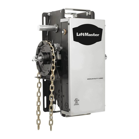
Your model may look different than the model illustrated in this manual.
NOT FOR RESIDENTIAL USE
THIS PRODUCT IS TO BE
INSTALLED AND SERVICED BY A
TRAINED DOOR SYSTEMS
TECHNICIAN ONLY.
Visit www.liftmaster.com to locate a
professional installing dealer in your area.
OPERATOR RATING: 12 cycles per hour,
50 cycles per day; maximum
Advertisement
Table of Contents

Related Manuals for Chamberlain LiftMaster MJ5011U


Summary of Contents for Chamberlain LiftMaster MJ5011U
- Page 1 MEDIUM DUTY DOOR OPERATOR MODELS MJ5011U, MH5011U, MHS5011U, & MGJ5011U INSTALLATION MANUAL Your model may look different than the model illustrated in this manual. 2 YEAR WARRANTY THIS PRODUCT IS TO BE INSTALLED AND SERVICED BY A Serial # TRAINED DOOR SYSTEMS (located on electrical box cover) TECHNICIAN ONLY.
-
Page 2: Table Of Contents
ENTRAPMENT PROTECTION 16-19 LiftMaster Monitored Entrapment Protection (LMEP) ..16 Install the Photoelectric Sensors....17 Mount the Photoelectric Sensors ....18 Entrapment Protection Wiring Options . -
Page 3: Safety Information
WARNING SAFETY INFORMATION WARNING WARNING CAUTION CAUTION WARNING Mechanical When you see this Signal Word on the following pages, it will CAUTION WARNING alert you to the possibility of damage to your door and/or the door WARNING WARNING operator if you do not comply with the cautionary statements that accompany it. -
Page 4: Application
APPLICATION This operator includes a number of features that will provide years of reliable and safe operation. FEATURES: • Supports both monitored and non-monitored entrapment protection devices: Entrapment protection devices detect obstructions in the door's path and automatically reverse a closing door. -
Page 5: Operator Specifications
OPERATOR SPECIFICATIONS WEIGHTS AND DIMENSIONS MODELS MH, MJ, AND MHS Hanging Weight: 60-70 LBS. (27.22-31.75 kg) 12.69" 6.13" (32.23 cm) (15.57 cm) 6.34" 6.34" MOUNTING DIMENSIONS 3.25" (16.1 cm) (16.1 cm) (8.26 cm) A - Wall Mounting B - Bracket Mounting (rolling door) 3.1"... -
Page 6: Motor
OUTPUT RPM: LiftMaster Monitored Entrapment Protection (LMEP) MJ......... 80 RPM Photoelectric Sensors (CPS-U): . -
Page 7: Preparation
PREPARATION PREPARING YOUR DOOR The manufacturer recommends 3 feet (91.4 cm) of clearance in front of operator for serviceability. Before you begin: • Disable locks. • Remove any ropes connected to door. • Before the operator is installed, be sure the door has been properly aligned and is working smoothly. Although each installation will vary due to particular building characteristics, refer to the following general procedures to install the operator. -
Page 8: Typical Installation
TYPICAL INSTALLATION NOTE: The illustrations may not depict your installation. DETERMINE MOUNTING LOCATION FOR OPERATOR The operator may be mounted on the wall, shelf or bracket (not provided, see accessories or door manufacturer). The optimum distance between the door shaft and operator drive shaft is 12-15 inches. WALL MOUNT SHELF OR BRACKET MOUNTING Door Shaft... - Page 9 TYPICAL INSTALLATION INSTALL THE OPERATOR Wrap drive chain around door sprocket. Wrap drive chain around operator sprocket. Door Sprocket Drive Chain Electrical Box Door Sprocket Operator Drive Sprocket Drive Chain Master Link Position the operator until chain is taut (not tight). If chain is too tight, it may Door Sprocket cause damage to operator.
-
Page 10: Install Emergency Disconnect System
TYPICAL INSTALLATION INSTALL EMERGENCY DISCONNECT SYSTEM MODELS MH AND MHS ONLY MODELS MJ AND MGJ ONLY The MHS operator includes both a floor level disconnect sash Secure keyhole bracket to wall 4 feet above the floor. chain to disconnect the door from the door operator that allows manual push up operation and an additional sash chain to engage the manual chain hoist that also electrically disables the operator controls. -
Page 11: Power And Ground Wiring Connections
TYPICAL INSTALLATION WARNING POWER AND GROUND WIRING CONNECTIONS WARNING WARNING To reduce the risk of SEVERE INJURY or DEATH: • ANY maintenance to the operator or in the area near the • ALL electrical connections MUST be made by a qualifi ed operator MUST NOT be performed until disconnecting the individual. -
Page 12: Install 3-Button Control Station
TYPICAL INSTALLATION POWER AND GROUND WIRING CONNECTIONS Attach power and ground wires to terminals. Power Control Line Power 115 Vac Single Phase WARNING INSTALL 3-BUTTON CONTROL STATION WARNING WARNING To prevent possible SERIOUS INJURY or DEATH from electrocution: • Install the entrapment warning placard on wall next to the •... -
Page 13: Setup Radio Antenna
TYPICAL INSTALLATION INSTALL 3-BUTTON CONTROL STATION Fasten the entrapment warning placard next to the control Connect wires to the control station and replace the control station cover. station. Power AUX ANT ^^^^ AUX ANT AUX ANT LEARN STOP CLOSE OPEN Entrapment LMEP1 LMEP2 COM INTRLK STOP... -
Page 14: Important Safety Instructions
TYPICAL INSTALLATION SETUP RADIO ANTENNA OPTION B Locate the wire antenna on the outside of the electrical box. Attach the antenna to the electrical box using the wire tie Cut wire ties and discard standoff. holes. Bend antenna across the front of the electrical box, ensuring that the antenna is 4 inches away from the front of the electrical box. -
Page 15: Adjustment
ADJUSTMENT WARNING ADJUST THE LIMITS WARNING WARNING To avoid SERIOUS personal INJURY or DEATH from • Disconnect electric power BEFORE performing ANY electrocution: adjustments or maintenance. Depress retaining plate. Adjust OPEN limit. Adjust CLOSE limit. Retaining Plate OPEN Limit Nut Decrease OPEN Limit Switch Increase... -
Page 16: Entrapment Protection
A LiftMaster Monitored Entrapment Protection (LMEP) device is BEFORE installing the photoelectric sensor. required for most wiring types. If a LiftMaster Monitored • The door MUST be in the fully opened or closed position Entrapment Protection device is not installed, constant pressure to BEFORE installing the LiftMaster Monitored Entrapment close will be required from the control station. -
Page 17: Install The Photoelectric Sensors
ENTRAPMENT PROTECTION INSTALL THE PHOTOELECTRIC SENSORS The following instructions show recommended assembly of the bracket(s) and “C” wrap based on the wall installation of the photoelectric sensors on each side of the door or on the door tracks themselves. There are also alternate mounting methods which may fi... -
Page 18: Mount The Photoelectric Sensors
ENTRAPMENT PROTECTION MOUNT THE PHOTOELECTRIC SENSORS Center each sensor in the bracket with the lenses pointing toward each other across the door. Wing Nut Wire “C” Wrap Attach the sensors to the brackets with the provided hardware. Finger tighten the receiving sensor wing nut. Indicator Light Securely tighten the sending sensor wing nut. -
Page 19: Logic Board Layout
ENTRAPMENT PROTECTION ENTRAPMENT PROTECTION WIRING OPTIONS ALTERNATE INSTALLATIONS: CPS-U PHOTOELECTRIC SENSOR WITH 2-WIRE SENSING EDGE 2-wire electric or pneumatic sensing edge (White) (White/Black) CPS-U PHOTOELECTRIC SENSOR WITH 4-WIRE SENSING EDGE 4-wire electric sensing edge (White/Black) (White) 2-WIRE ELECTRIC OR PNEUMATIC SENSING EDGE (B2 NOT AVAILABLE) 2-wire electric or pneumatic sensing edge (White/Black) (White) -
Page 20: Basic Programming
The functionality of this operator is based on the wiring type. The operator is shipped from the factory in standard C2 wiring type (factory default). LIFTMASTER MONITORED ENTRAPMENT PROTECTION (LMEP) DEVICE IS RECOMMENDED. A LiftMaster Entrapment Protection (LMEP) device is required for any momentary contact to close mode of operation including B2, TTC and remote controls. -
Page 21: Remote Controls
BASIC PROGRAMMING DETERMINE THE WIRING TYPE ALTERNATE INSTALLATION: C2 WIRING TYPE WITH MONITORED ALTERNATE INSTALLATION: C2 WIRING TYPE WITHOUT ENTRAPMENT PROTECTION DEVICE MONITORED ENTRAPMENT PROTECTION DEVICE (FACTORY DEFAULT) • Momentary contact to open and stop with constant pressure to • Momentary contact to open and stop with constant pressure to close. -
Page 22: Timer-To-Close (Ttc)
REMOTE CONTROLS WARNING WARNING To prevent possible SEVERE INJURY or DEATH: • Install a LiftMaster Monitored Entrapment Protection (LMEP) • Activate door ONLY when it can be seen clearly, is properly CAUTION device. adjusted and there are no obstructions to door travel. -
Page 23: Testing
TEST LIMIT ADJUSTMENT TEST REMOTE CONTROL Press OPEN button. (The door should open.) Requires B2 wiring type and compatible LiftMaster remote control. In C2 wiring the remote control will open the door only. Allow the door to fully open. Press remote control button. -
Page 24: Emergency Disconnect
WARNING EMERGENCY DISCONNECT WARNING WARNING To prevent possible SERIOUS INJURY from a moving chain: • DISCONNECT electric power to the operator BEFORE manually • NEVER use emergency disconnect unless doorway is clear of operating your door. persons and obstructions. • If possible, use emergency disconnect ONLY when door is CLOSED. -
Page 25: Troubleshooting
C) TTC not programmed ➤ Reprogram TTC. See PROGRAMMING TTC section. properly RADIO FUNCTIONALITY NOTE: Built in radio receiver compatible with all LiftMaster 315 MHz remote control devices. A) Remote control is not ➤ See PROGRAMMING REMOTE CONTROLS section. NO RESPONSE... -
Page 26: Diagram
TROUBLESHOOTING The status of the operator can be determined by counting the number of flashes of the LED on the logic board. DIAGNOSTIC LED TABLE # OF LED FLASHES STATUS System OK. Operating in C2 mode None System OK. Operating in B2 mode None Stuck CLOSE button Check for stuck close button or shorted close wire... -
Page 27: Accessories
ACCESSORIES ENTRAPMENT PROTECTION DEVICES REMOTE CONTROLS 315 MHZ CPS-UN4 ® LiftMaster offers a variety of SECURITY✚ Remote Controls for your application needs. Single to 4-Button, Commercial Protector System: visor or key chain. Contact your authorized dealer. LiftMaster Monitored Entrapment Protection (LMEP) 371LM provides protection on doors up to 45' wide. -
Page 28: Control Connection Diagram
CONTROL CONNECTION DIAGRAM IMPORTANT NOTES: 1. The 3-Button Control Station provided must be connected for operation. 2. If a STOP button is not used, a jumper must be placed between terminals 3 and 5. 3. If INTERLOCK is not used a jumper must be placed between terminals 3 and 4. 4.