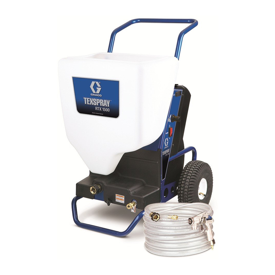
Graco RTX 1500 Repair And Parts Manual
Electric texture sprayer
Hide thumbs
Also See for RTX 1500:
- Repair and parts manual (39 pages) ,
- Operation (35 pages) ,
- Operation and parts (31 pages)
Table of Contents
Advertisement
Repair and Parts
RTX 1500 Electric Texture Sprayer
U.S. Patent No. D580,517S
Europe Patent No. 1511575
(Consult your Material Supplier for Warnings and Application Requirements)
Models: Page 2
Maximum Working Air Pressure: 45 psi (3.1 bar)
Maximum Working Fluid Pressure: 100 psi (6.9 bar)
Important Safety Instructions
Read all warnings and instructions in this
manual. Save these instructions.
NOTICE
Use RTX 1500 non-bleeder texture gun 248091.
All other guns will damage sprayer.
- For Water-Based Materials Only -
310645L
ENG
ti4305a
Advertisement
Table of Contents

Related Manuals for Graco RTX 1500


Summary of Contents for Graco RTX 1500
- Page 1 Maximum Working Air Pressure: 45 psi (3.1 bar) Maximum Working Fluid Pressure: 100 psi (6.9 bar) Important Safety Instructions Read all warnings and instructions in this manual. Save these instructions. NOTICE Use RTX 1500 non-bleeder texture gun 248091. All other guns will damage sprayer. ti4305a...
-
Page 2: Related Manuals
Models Models Manual Country Languages Model Electric 287328* Requirements Operation 248201 120V, 60 Hz, 15 A N. America 310624 310694 310616 English 248370 / 248315 230V. 50 Hz, 10 A Europe 310624 310616 French 248370 230V. 50 Hz, 10 A Europe 310624 Dutch... - Page 3 Check equipment daily. Repair or replace worn or damaged parts immediately. • Do not alter or modify this equipment. • Use the equipment only for its intended purpose. Call your Graco distributor for information. • For professional use only. •...
-
Page 4: Personal Protective Equipment
Warnings WARNING SKIN INJECTION HAZARD High-pressure fluid from gun, hose leaks, or ruptured components will pierce skin. This may look like just a cut, but it is a serious injury that can result in amputation. Get immediate surgical treatment. • Do not point gun at anyone or at any part of the body. •... -
Page 5: Component Identification
Component Identification Component Identification ti4500a 310645L... - Page 6 Component Identification Component Identification ITEM COMPONENT Main Power Switch Nozzle Storage Hopper Hopper Connect/Disconnect Graco RotoFlex™ HD Pump Material Outlet Air Outlet Fluid Flow Regulator and Pressure Gauge Gun Nozzle (5 sizes) Gun (see manual 310616)* Prime Switch Power Cord Pump Access Screw Hose - 25-ft.
-
Page 7: Preparation
Preparation Preparation Pressure Relief Procedure Grounding and Electric Requirements 1. Turn Main Power Switch (A) OFF. The sprayer must be grounded. Grounding reduces the risk of electrical shock by providing an escape wire for the electrical current. 2. Turn fluid flow regulator (K) all the way down to reduce pressure. -
Page 8: Hose Lengths
Preparation Auxiliary Air Compressor Hose Lengths • Use Auxiliary Air Hookup Kit 287328 when addi- • The system comes with a twin line hose set consist- tional atomization air is necessary. ing of a 1 in. ID x 25 ft (25 mm x 7.6 m) material hose and a 3/8 in. -
Page 9: Front Cover
Removing and Replacing Hopper, Front and Back Covers Removing and Replacing Hopper, Front and Back Covers Before performing any service on sprayer Front Cover always: Removing Cover • Read all warnings, page 3. 1. Remove hopper. • Read operating instructions manual, page 2. •... -
Page 10: Back Cover
Removing and Replacing Hopper, Front and Back Covers Back Cover To access the motor and all other components, it is nec- Replacing Cover essary to remove the hopper, front and back covers. 1. To reposition cover on sprayer Removing Cover frame, tip the cover back, toward 1. - Page 11 RotoFlex™ HD Pump RotoFlex™ HD Pump Use RotoFlex HD Pump Replacement Kit 287314. 4. Rotate pump assem- bly sideways. Pull NOTE: After replacing RotoFlex HD Pump hose, always entire assembly out of follow Hose Break-In Procedure, page 13, before oper- front of sprayer frame.
- Page 12 RotoFlex™ HD Pump Reassembly 5. Replace bracket assembly in housing making sure the 1. Bend and kink new DOTS mounting screw hole, pump hose from kit in located in the top the middle as shown, center of the inner making sure dots on plate, faces up.
- Page 13 RotoFlex™ HD Pump Hose Break-In Procedure 1. Make sure fluid flow regula- 3. Turn power switch (A) on. tor (K) is turned all the way down. ti4653a 4. Hold in prime switch (P). ti4303a 2. Pour approxi- mately 1 gallon hot water in WATER sprayer hopper to...
-
Page 14: Compressor And Motor Repair
Compressor and Motor Repair Compressor and Motor Repair For 120 V sprayer use Compressor and Motor Replace- 4. Loosen 4 bolts (2 each ment Kit, 287315. side) to loosen tension on belt. For 230 V sprayer use Compressor and Motor Replace- ment Kit, 287344. - Page 15 Compressor and Motor Repair 8. Loosen 2 shoulder Reassembly bolts about 2-3 turns. Do not remove them. 1. Using two new shoulder bolts and rubber mounts included in your kit, insert bolts into openings until they start to snug up on ti4463a rubber mounts.
- Page 16 Compressor and Motor Repair 7. Reattach black and white 9. Replace cover plate and wires to motor. screws. 10. Replace RotoFlex HD NOTE: Wires are not polar- Pump and hose exten- ity sensitive. sion, page 12. 11. Replace front and back covers and hopper.
- Page 17 Compressor Rebuild Kit Compressor Rebuild Kit To replace piston, seals and sleeve. 4. Remove 3/8 in. bolt holding piston to For 120 V sprayer use Compressor Rebuild Kit 287330. motor shaft. For 230 V sprayer use Compressor Rebuild Kit 287331. ti4707a Disassembly First read and follow instructions in the Before perform-...
- Page 18 Compressor Rebuild Kit Reassembly 5. Replace motor fan and center fan bolt. 1. Insert new piston rod from kit in motor housing. 6. Tighten bolt. ti4704a ti4700a 7. Replace motor cover and 2. Replace and screws. tighten piston bolt. 3. Replace top motor hosing and 4 bolts.
-
Page 19: Replacing Belt
Removing and Replacing Belt Removing and Replacing Belt Replacing Belt Use Belt Replacement Kits 118845. First read and follow instructions in the Before perform- 1. Using new belt from Kit, ing any service on sprayer section, page 9. position new belt around pulleys making Then remove hopper, front and back covers, page 9. - Page 20 Removing and Replacing Belt 5. Tighten all 4 bolts. NOTE: A correctly tensioned belt will feel very tight. To measure correct tension, apply 4-5 lbs pressure at belt midpoint with thumb. Belt should have approximately 1/8 in. (3.175 mm) deflec- tion.
-
Page 21: Roller Replacement
Roller Replacement Roller Replacement Reassembly Use Roller Replacement Kit 287321. Kit includes 2 rollers, 4 nylon washer, and 2 retaining 1. Replace roller assembly. rings. Disassembly ti4398a First read and follow instructions in the Before perform- ing any service on sprayer section, page 9. Then remove hopper, front and back covers, page 9. - Page 22 Rotor Assembly Replacement Rotor Assembly Replacement Reassembly Use Pump Assembly Replacement Kit 287255. 1. Put new rotor assembly from kit on shaft. Disassembly 2. Insert a wrench in the First read and follow instructions in the Before perform- pulley to prevent it from ing any service on sprayer section, page 9.
-
Page 23: Air Cylinder And Solenoid Valve
Air Cylinder and Solenoid Valve Air Cylinder and Solenoid Valve Use Cylinder Replacement Kit, 287323. 4. Gently push cylinder forward, relieving For 120 V sprayer use Solenoid Replacement Kit tension on pin. Pull 287324. out pin. For 230V sprayer use Solenoid Replacement Kit 287351. - Page 24 Air Cylinder and Solenoid Valve Reassembly 6. Replace cotter pin through hole in pin, bending ends to 1. Insert crowned backing secure. nut on shaft of cylinder. 2. Using new cylinder from kit, position cylinder in ti4456a sprayer frame, inserting ti4421a 7.
- Page 25 Relief Valve and Flow Sensor Manifold Relief Valve and Flow Sensor Manifold For 120 V sprayer use Relief Valve Replacement Kit 5. Remove Relief Valve 287325. from sprayer frame. For 230 V sprayer use Relief Valve Replacement Kit 287350. Disassembly ti4419a First read and follow instructions in the Before perform- ing any service on sprayer section, page 9.
-
Page 26: Air Flow Sensor Replacement
Air Flow Sensor Replacement Air Flow Sensor Replacement For 120 V sprayer use Sensor Replacement Kit 287326. 2. Rotate counter-clockwise to remove sensor from For 230 V sprayer use Sensor Replacement Kit 287345. manifold. If you are just replacing the sensor, you do not have to remove the motor first. -
Page 27: Troubleshooting
Troubleshooting Troubleshooting Problem Cause Solution Sprayer won’t run or stops intermit- Power switch not on Turn switch on. tently No power at wall outlet Check outlet by plugging in another appliance. If appliance does not work, try another outlet. Wrong size generator Use a 7500 watt or larger generator. - Page 28 Damaged hose Replace hose. Worn compressor Service compressor. Contact a quali- fied Graco Service Center. Speed of application too slow Material too thick Thin material. Nozzle too small Change nozzles to a larger size. See Operation Manual, Recommended Nozzle Selection Chart, page 20.
-
Page 29: Air Diagram
Air Diagram Air Diagram Air Cylinder Air Compressor Air Cooler Regulator Guage One Way Valve One Way Valve Air Flow Control ti4369a Wiring Diagram Air Compressor Air Cylinder Prime Switch Power 150/151 Switch Air Flow Control Green White Black ti4370d 310645L... - Page 30 Parts Parts ti4371b 310645L...
-
Page 31: Parts List
Parts List Parts List Ref. Part Description Qty. Ref. Part Description Qty. 103785 RIVET 287315 KIT, compressor replacement 287327 KIT, repair, shaft, bracket, pump (includes 1A and 1B-1E), assbly. 120V sprayers 287256 BRACKET, compressor 287330 KIT, compressor rebuild, 120V sprayers 118869 TUBE 287344 KIT, compressor replacement 15D610 SHAFT, motor, mount... - Page 32 Parts Parts ti4372C 150a 152a 152b 152c 152d 152e 150b 150c 310645L...
- Page 33 Parts List Parts List Ref. Part Description Qty. Ref. Part Description Qty. 15D634 WIRE, jumper 118844 REGULATOR, air, 1/8 in. NPT 116666 TUBE, air 287323 KIT, cylinder, replacement, 287304 HOSE SET, twin line, 1 in. x 25-ft (includes 5A, 5B, 89) 116720 COUPLER, air, quick disconnect 15D576...
-
Page 34: Technical Data
Technical Data Technical Data Maximum working fluid pressure 100 psi (6.9 bar) Maximum working air pressure 45 psi (3.1 bar) Material pressure operating range 0-100 psi (0 to 6.9 bar) Compressor Type Oilless Air delivery 6.5 CFM @ 40 psi (184.1 lpm @ 2.8 bar) Motor 120V, 60 Hz 15A 230V, 50 Hz 10A... - Page 35 Notes Notes 310645L...
-
Page 36: Graco Standard Warranty
With the exception of any special, extended, or limited warranty published by Graco, Graco will, for a period of twelve months from the date of sale, repair or replace any part of the equipment determined by Graco to be defective.