Table of Contents
Advertisement
Quick Links
Advertisement
Table of Contents

Related Manuals for Electrolux European Wine Tower


Summary of Contents for Electrolux European Wine Tower
- Page 1 Service Manual European Wine Tower 5995534509 March 2009...
-
Page 2: Safe Servicing Practices - All Appliances
Electrolux Home Products cannot be responsible, nor assume any liability, for injury or damage of any kind arising from the use of this manual. -
Page 3: Table Of Contents
Table of Contents Safe Servicing Practices - All Appliances....2 Soldering ..............21 Basic Components ............. 21 A - Installation..........4 Refrigerant Cycle ............21 Important safety instructions ........4 Low/High Side Leak or Undercharge ......21 General Precautions ............. 4 Testing for Refrigerant Leaks ........ -
Page 4: A - Installation
Indicates installation, operation or maintenance information which is important but not hazard- CAUTION related. • Use only genuine Electrolux replacement parts. Imitation parts can damage the unit and may void the warranty. WARNING The Anti-tip bracket (supplied with unit) must be installed on a solid surface. -
Page 5: Installing The Wine Tower
Installing the Wine Tower Your Electrolux Wine Tower has been designed for either free-standing or built-in installation. When built-in, your wine keeper does not require additional air space for top, sides or rear. In either case, the front grille must NOT be obstructed. -
Page 6: Site Preparation
A - Installation Site Preparation CAUTION 1 Position the unit on a flat, level surface capable DO NOT install the wine keeper where the of supporting the entire weight of the unit. temperature will drop below 55°F (13°C) or rise Remember the unit will be significantly heavier above 110°F (43°C). - Page 7 A - Installation All of these conditions can be met by raising or lowering the adjustable leveling legs. To level the cabinet using the leveling legs: 1 Open the door and remove the toe grille by gently pressing down on top edge to release snaps and pull forward.
-
Page 8: Door Handle Mounting Instructions
A - Installation Door Handle Mounting Instructions 1 Remove handle from carton and any other protective packaging. 2 Position handle end caps over upper and lower pre-installed shoulder bolts (A) that are fastened into door, ensuring the holes for the set screws are facing towards the outside edge of the door. 3 While holding handle firmly against door, fasten upper and lower Allen set screws (B) with supplied Allen wrench. -
Page 9: Starting The Unit
A - Installation Starting the Unit Your wine keeper is shipped in the ON position; however, you may turn it ON or OFF by pressing the ON/OFF for three (3) seconds. Adjusting the Temperature To accurately check the temperature, insert a reliable thermometer into a plastic (non-breakable) bottle, partially filled with water. -
Page 10: Description Of Features
A - Installation Description of Features high temp In the event of a high temperature condition, vacation mode Conserves energy by disabling interior lights an audible alarm will sound, the temperature and keypad inputs. display will blink and display “HI” and the high mute sounds Tones emitted by each keypress can be turned temp indicator on the right side of the display... -
Page 11: B - Maintenance
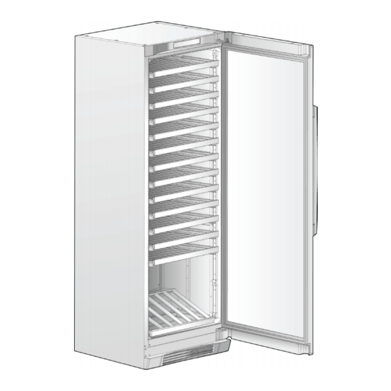
B - Maintenance Proper Storage Maintaining Your Wine Tower The wine tower can accommodate more than 160 Periodic cleaning and proper maintenance will ensure bottles (typical 750 ml size). There are thirteen (13) efficiency, top performance, and long life. The mainte- upper racks that will hold ten (10) bottles each and nance intervals listed are based on normal conditions. -
Page 12: Wine Rack Removal/Installation
Ordering replacement filters Order new filters by calling toll-free, 877/808-4195, visiting www.electroluxappliances.com, or seeing the dealer where you bought your wine tower. Electrolux recommends that you order extra filters when you first install your wine keeper, and that you replace your filters at least once every six months. -
Page 13: C - Electrical Components / Operation
C - Electrical Components / Operation Electrical Grounding Solid State Relay The solid state relay has no moving parts. It consists All refrigerators are equipped with a power supply of a PTC resistor mounted in a plastic case with cord incorporating a three-prong grounding plug and appropriate terminals. -
Page 14: To Check/Replace Relay
C - Electrical Components / Operation To Check/Replace Relay 7. If ohm readings are out of range, install new Starter/Overload Assembly. See Figure 2. 1. Disconnect electrical supply to refrigerator. 8. Reverse this procedure to re-assemble. 2. Remove bale wire holding relay to compressor. -
Page 15: Compressor Start Circuit
C - Electrical Components / Operation Compressor Operating Compressor Start Circuit When the compressor circuit is first energized, the Characteristics solid state relay has low resistance (3-12 ohms), • When the compressor electrical circuit is and both the run and start windings are energized energized, the start winding current causes to start the compressor. -
Page 16: Compressor Electrical Check
C - Electrical Components / Operation Compressor Electrical Check Diagnostics / Service Mode If the compressor will not run, make a voltage To enter the service mode, press and hold the check across the power lead terminals on the PTC vacation mode key, while pressing the on/off key 3 Relay. -
Page 17: System Error Codes
C - Electrical Components / Operation Evaporator Circulation Motor System Error Codes The Wine Tower uses two 12 vdc evaporator fan Primary Sensor Open Display will flash “P2” circulation motors driven by the Main PCB Board @ 1 hz. located on top of the unit. Primary Sensor Display will flash “P3”... -
Page 18: Wiring Diagrams
C - Electrical Components / Operation Electrical Wiring Diagram... - Page 19 C - Electrical Components / Operation Electrical Wiring Diagram...
-
Page 20: D - Refrigeration System
D - Refrigeration System Safety Warnings NOTICE Compressor Testing Instructions given here are furnished as a guide. Persons attempting to use these instructions to Whenever testing a compressor, extreme caution make repairs to the sealed refrigeration system should be used to prevent damaging the terminals. should have a working knowledge of refrigeration A compressor with a damaged terminal or a and previous training on sealed system repair,... -
Page 21: Soldering
D - Refrigeration System Soldering Refrigerant Cycle The refrigerant cycle is a continuous cycle that WARNING occurs whenever the compressor is in operation. Liquid refrigerant is evaporated in the evaporator Wear approved safety glasses when working by the heat that enters the cabinet through the with or on any pressurized system or insulated walls and by the heat from product load equipment. -
Page 22: Testing For Refrigerant Leaks
D - Refrigeration System If there is reason to believe the system has • If oil has a burned odor and a sugar operated for a considerable length of time with no or gritty feel as well as showing signs refrigerant and the leak occurred in the low side of of contamination (dark color) —... -
Page 23: To Use Refrigerant To Flush The System
D - Refrigeration System Installing a New Compressor Disconnect cap tube from evaporator. Flush evaporator in same manner as condenser. NOTE CAUTION Entirely new compressors have been developed for use with R-134a and Ester oil refrigeration DO NOT exceed 150 PSIG. systems. - Page 24 D - Refrigeration System A new compressor which is cold (e.g. after having NOTE been kept in a cold service van) should be left to warm to the surrounding temperature before the If low-side process tube is too short, silver solder plugs on the compressor connections are removed.
- Page 25 D - Refrigeration System Figure E1 Access Cover Fan Motor Fan Blade Condenser Drier Filter Compressor Suction Tube Connector PTC-Starter Run Capacitor Clip Defrost Drain Pan...
-
Page 26: Condenser Replacement
D - Refrigeration System Condenser Replacement CAUTION Disconnect electrical supply to refrigerator. Use only a 15 gram XH9 liquid line filter-drier Remove compressor access panel. (part number 5303305677) when servicing refrigerator and freezer systems. This filter- Recover refrigerant by using EPA approved drier is compatible with either R-12 or R-134a recovery system. -
Page 27: Evaporator And Suction Line Replacement
D - Refrigeration System Evaporator and Suction line excess cap tube can be wound around the suction line. Replacement Seal the hole on the inside and outside using To replace the heat exchanger: Permagum. The one piece cover can now be installed The original heat exchanger (suction line and over heat exchanger. -
Page 28: Evacuating And Recharging
D - Refrigeration System Equipment Needed for Evacuation & CAUTION Recharging: Check the serial plate for the correct • Heated charging cylinder refrigerant type. It is extremely important to • Standard 3-port manifold gauge set: verify the type of refrigerant in the system before starting any sealed system repairs. -
Page 29: Evacuating System
D - Refrigeration System Evacuating System refrigerant using EPA approved recovery system Repair and go back to step 1. WARNING Charging the System R-134a systems are particularly susceptible CAUTION to moisture contamination which can only be prevented by evacuating the system for a Check the serial plate for the correct minimum of 30 minutes to attain a minimum refrigerant type. -
Page 30: Final Leak Test
D - Refrigeration System Final Leak Test Close both of the manifold gauge valves. If the high-side gauge reading rises, the pinch- off must be corrected before proceeding. With the refrigerator turned OFF leak test all low-side system components. Remove the high-side process tube adaptor and solder the process tube closed. -
Page 31: Verify Refrigerant Type In The System
D - Refrigeration System Products using R-134a refrigerant will generally NOTICE have a longer capillary tube to maintain a similar Instructions given here are furnished as a guide. flow rate and some models will have a larger Persons attempting to use these instructions to condenser to reduce the discharge pressures and make repairs to the sealed refrigeration system lower start-up sound transmission. -
Page 32: Water In The Refrigeration System
D - Refrigeration System At the earliest stage of development work on To achieve the required 29.9 inch (500 micron) R-134a, tests were carried out on a different type of vacuum, a properly maintained two-stage vacuum synthetic oil known as Poly-Alkaline Glycol (PAG). pump in good condition is required. -
Page 33: Refrigerant Leaks
Electrolux Home products does not approve the use of the Sweep Charge for sealed system Refrigerant Leaks repair. This method of servicing sealed systems... -
Page 34: Leak Detection
D - Refrigeration System Leak Detection major advantage of this type of detector is a reduction in the number of “nuisance alarms”. R-134a system leaks can be pinpointed by means Halogen-specific detectors are generally more of an electronic leak detector or by bubble solution. expensive than non-selective detectors but feature higher sensitivity. -
Page 35: Hfc-134A, Cfc-12 Pressure Temperature Chart
D - Refrigeration System HFC-134a, CFC-12 Pressure Temperature Chart °F °C HFC-134a CFC-12 °F °C HFC-134a CFC-12 -51.1 21.8* 19.0* 12.8 51.1 52.0 -48.3 20.4* 17.3* 15.6 57.3 57.7 -45.6 18.7* 15.4* 18.3 63.9 63.8 -42.8 16.9* 13.3* 21.1 70.9 70.2 -40.0 14.8*... -
Page 36: Inhalation Toxicity
D - Refrigeration System Inhalation Toxicity Spills or Leaks HFC-134a poses no acute or chronic hazard If a large release of vapor occurs, such as from when it is handled in accordance with DuPont a large spill or leak, the vapors may concentrate recommendations and when exposures are near the floor or low spots and displace the oxygen maintained at or below the DuPont Acceptable... -
Page 37: Combustibility Of Hfc-134A
D - Refrigeration System Filling and Charging Operations Always wear protective clothing when there is a risk of exposure to liquid HFC-134a. Where • Before evacuating cylinders or refrigeration splashing is possible, always wear eye protection equipment, any remaining refrigerant should and a face shield. -
Page 38: Exploded View Diagrams
Exploded View Diagrams SYSTEM DIAGRAM Publication No: 5995532214 EI24WC75HS0 SYSTEM W05CAAAAA1... - Page 39 Exploded View Diagrams EI24WC75HS0 Publication No: 599553 SYSTEM DESCRIPTION SYSTEM POS. NO PART NO. DESCRIPTION 7241999401 Condenser, dynamic 75304406721 Spacer-cond tube, round, 5/8 OD x .81"lg 7218944002 Drier-filter, R134a System 7241516901 Cord-service 7242005101 Harness-wiring, machine compt 7242005501 Harness, UI 7241888101 Base-compressor 7218252201 Screw, #8 truss hd, 10-32CA x 0.500...
-
Page 40: Cabinet Diagram
Exploded View Diagrams Publication No: 5995532214 EI24WC75HS0 CABINET DIAGRAM CABINET W05BAAAAA0... - Page 41 Exploded View Diagrams EI24WC75HS0 Publication No: 599553 CABINET DESCRIPTION CABINET POS. NO PART NO. DESCRIPTION 7242036001 Cover-fan 7242036101 Screw, M4 x 35 7242039301 7242035901 Leg-leveling 7242003401 Cover-evap coil 7242036201 Screw 13 # 7242002701 Motor-evap fan 15 # 7242002901 Evaporator 7242003101 Trough-drain 7242004701 Panel-front, lower...
-
Page 42: Door Diagram
Exploded View Diagrams DOOR DIAGRAM Publication No: 5995532214 EI24WC75HS0 DOOR W05DAAAAA0... - Page 43 DOOR POS. NO PART NO. DESCRIPTION 7242001801 Gasket-door 7242001601 Plug-hole, hinge pin 7242000601 Panel-door, Glass w/frame 7241873307 Nameplate, Electrolux 7242001201 Door Stop, wine tower 7241881304 Handle-refr door, stainless 7241601002 Wrench, allen 7242001501 Screw, end cap 7242001301 Screw, door stop 7242001701...
-
Page 44: Shelves
Exploded View Diagrams SHELVES DIAGRAM Publication No: 5995532214 EI24WC75HS0 SHELVES W05SAAAAA0... - Page 45 Exploded View Diagrams SHELVES DESCRIPTION EI24WC75HS0 Publication SHELVES POS. NO PART NO. DESCRIPTION 7242002501 Slide, shelf 7242002601 Shelf-Wine Rack 7242005901 RACK-DISPLAY 7242002301 Channel-shelf mtg, side 7242002401 Screw-channel mtg 7242038901 Support, display rack 7242016601 Housing-air filter 7241754001 Filter-air 7241754302 Sleeve, air filter, silver, front 75304468028 Customer Instruct DVD...
-
Page 46: Service Data Sheet
View View (191-193 cm) Watts amps 3.00” Your Electrolux wine keeper has been designed for either (7.62 cm) 1100 CW Opposite Shaft 0.15 Running free-standing or built-in installation. When built-in, your wine 49” keeper does not require additional air space for top, sides or WiNe cOOLer evapOratOr faN mOtOr (Quantity 2) (124.46 cm)