Table of Contents
Advertisement
Advertisement
Table of Contents

Related Manuals for Icom IC-M601


Summary of Contents for Icom IC-M601
- Page 1 INSTRUCTION MANUAL VHF MARINE TRANSCEIVER iM601...
-
Page 2: Foreword
We want to take a couple of moments of your time to The optional COMMANDMIC provides a 2nd and 3rd thank you for making the IC-M601 your radio of choice, station capability and an intercom function. With slim and hope you agree with Icom’s philosophy of “tech- dimension and sizable LCD, the COMMANDMIC offers nology first.”... -
Page 3: Important
Icom, Icom Inc. and the logo are registered trademarks This warning symbol indicates that this equip- of Icom Incorporated (Japan) in the United states, the United ment operates in non-harmonised frequency bands Kingdom, Germany, France, Spain, Russia and/or other coun- and/or may be subject to licensing conditions in the tries. -
Page 4: In Case Of Emergency
IN CASE OF EMERGENCY If your vessel requires assistance, contact other vessels and Or, transmit your distress call using digital selective calling on the Coast Guard by sending a distress call on Channel 16. Channel 70. USING CHANNEL 16 USING DIGITAL SELECTIVE CALLING (Ch 70) DISTRESS CALL PROCEDURE DISTRESS CALL PROCEDURE... -
Page 5: Table Of Contents
TABLE OF CONTENTS I Position indication ......17 12 SPECIFICATIONS AND FOREWORD ..........i I Distress call ........18 IMPORTANT ..........ii OPTIONS ........47 I Transmitting DSC calls ....19 I Specifications ....... 47 EXPLICIT DEFINITIONS ......ii I Setting the distress information ..23 I Options ......... -
Page 6: Precaution
PRECAUTION RWARNING! NEVER AVOID the use of chemical agents such as benzine or al- connect the transceiver to an AC cohol when cleaning, as they may damage the transceiver outlet. This may pose a fire hazard or result in an electric surfaces. -
Page 7: Operating Rules
OPERATING RULES D D PRIORITIES (2) OPERATOR’S LICENSE A Restricted Radiotelephone Operator Permit is the license • Read all rules and regulations pertaining to priorities and most often held by small vessel radio operators when a radio keep an up-to-date copy handy. Safety and distress calls is not required for safety purposes. -
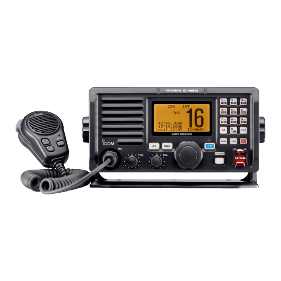
Page 8: Panel Description
PANEL DESCRIPTION I Panel description iM601 VHF MARINE Function display Speaker DIAL DISTRESS MIC connector (Connect HM-137 ONLY) CAUTION: NEVER connect other microphones here, such as the optional HM-134, may cause damage to the transceiver. - Page 9 PANEL DESCRIPTION q TRANSMIT POWER SWITCH [H/L] y CHANNEL 16/CALL CHANNEL SWITCH [16•C] ➥ Toggles high or low power when pushed. (p. 10) ➥ Selects Channel 16 when pushed. (p. 8) ➥ Selects call channel when pushed for 1 sec. (p. 8) •...
- Page 10 PANEL DESCRIPTION !2 KEYPAD ➥ Number input: ‘1’ ➥ Inputs numeral for channel number input, etc. ➥ Comment input: ‘1,’ ‘Q,’ ‘Z,’ ‘q,’ ‘z’ or space ➥ Inputs numeral and alphabet (some symbol) for channel ➥ After pushing [F], turns the DUALWATCH comment input.
- Page 11 PANEL DESCRIPTION ➥ Number input: ‘5’ ➥ Number input: ‘0’ ➥ Comment input: ‘5,’ ‘J,’ ‘K,’ ‘L,’ ‘j,’ ‘k’ or ‘l’ ➥ Number input: Push for 1 sec. to edit ‘A.’ ➥ After pushing [F], sets the displayed channel • Inputing “A” for simplex channels. ➥...
-
Page 12: I Function Display
PANEL DESCRIPTION I Function display e SCAN INDICATOR ➥ Either “NORMAL SCAN” or “PRI-SCAN 16” scan type appears while scanning. (p. 15) BUSY-25W---INT---CALL ➥ “DUAL 16” appears during dualwatch; “TRI 16” ap- LOCAL--DUP pears during tri-watch. (p. 13) SCRAM--TAG NORMAL-SCAN r POSITION INDICATOR ➥... -
Page 13: I Microphone (Hm-137)
PANEL DESCRIPTION I Microphone (HM-137) y CHANNEL COMMENT INDICATOR ➥ Channel comment appears if programmed. (p. 11) ➥ “Low Batt” flashes when the battery voltage drops to approx. 10 V DC or below. u CHANNEL NUMBER READOUT Speaker Indicates the selected operating channel number. “A”... -
Page 14: Basic Operation
BASIC OPERATION I Channel selection D D Channel 16 D D Call channel Channel 16 is the distress and safety channel. It is used for Each regular channel group has a separate leisure-use call establishing initial contact with another station and for emer- channel. - Page 15 BASIC OPERATION U.S.A. channels (depends on version) and International channels There are 58 U.S.A. channels in addition to 57 International channels. These channel groups may be specified for the op- erating area. q Push [DIAL] to select a regular channel. w While pushing [H/L], push [DIAL] to change the channel group, if necessary.
-
Page 16: I Receiving And Transmitting
BASIC OPERATION I Receiving and transmitting CAUTION: y Push and hold [PTT] to transmit, then speak into the mi- Transmitting without an antenna may dam- age the transceiver. crophone. • “TX” appears. q Push [POWER] to turn power ON. • Channel 70 cannot be used for transmission. w Set the audio and squelch levels. -
Page 17: I Call Channel Programming
BASIC OPERATION I Call channel programming I Channel comments The call channel is used to select Channel 9, however, you Memory channels can be tagged with alphanumeric names can program your most often-used channel in each channel of up to 10 characters each. group for quick recall. - Page 18 BASIC OPERATION • Available characters CHARACTERS CHARACTERS z (space) m n o...
-
Page 19: Dualwatch/Tri-Watch
DUAL WATCH/TRI-WATCH I Description I Operation q Select the desired operating channel. Dualwatch monitors Channel 16 while you are receiving an- w Push [F], then push [1 other channel; tri-watch monitors Channel 16 and the call ] to start dualwatch or [2 DUAL channel while receiving another channel. -
Page 20: Scan Operations
SCAN OPERATIONS I Scan types Scanning is an efficient way to locate signals quickly over a Set the tag channels (scanned channel) before scanning. wide frequency range. The transceiver has priority scan and Clear the tag channels which inconveniently stop scanning, normal scan. -
Page 21: I Setting Tag Channels
SCAN OPERATION I Setting tag channels I Starting a scan For more efficient scanning, add desired channels as tag Set scan type (priority or normal scan) and scan resume timer channels or clear tag channels for unwanted channels. Chan- in advance using set mode. (p. 38) nels set as non-tag channels will be skipped during scanning. -
Page 22: Dsc Operation
DSC OPERATION I MMSI code programming I Position and time programming The 9-digit MMSI (Maritime Mobile Service Identity: DSC self A distress call should include the ship’s position and time ID) code can be programmed at power ON. data. If no GPS is connected, your position and UTC (Univer- sal Time Coordinated) time should be input manually. -
Page 23: I Position Indication
• Push [CLR] to abandon the setting and exit the condition to the A GPS receiver appropriate for the IC-M601 is not supplied DSC menu. from Icom. A GPS receiver with NMEA0183 ver. 2.0 format is --DSC Menu-- required for position indication. -
Page 24: I Distress Call
DSC OPERATION I Distress call e After transmitting the distress call, the transceiver waits for A distress call should be transmitted, if in the opinion of the Master, the ship or a person is in distress and requires imme- an acknowledgment call on Ch 70. diate assistance. -
Page 25: I Transmitting Dsc Calls
DSC OPERATION I Transmitting DSC calls t When receiving the acknowledgment, reply using the mi- crophone. D D Transmitting Individual call BUSY-25W---INT---CALL The individual call function allows you to transmit a DSC sig- LOCAL--DUP SCRAM--TAG nal to a specific ship only. ReceivedCAN DistressACK q Push [MENU] to enter the DSC menu. - Page 26 •Intership channels are already preset into the transceiver in rec- Individual Call ommending order. TX Complete • When “Manual Input” is selected, rotate [CHANNEL] to se- ˘Icom Now Waiting for ACK lect the desired channel other than Channel 70. ˘Ricky --DSC Menu-- ˘...
- Page 27 DSC OPERATION D D Transmitting Group call r Rotate [CHANNEL] to select a desired intership channel or “Manual Input,” push [ENT]. The Group call function allows you to transmit a DSC signal •Intership channels are already preset into the transceiver in rec- to a specific group only.
- Page 28 DSC OPERATION D D Transmitting All ships call r Push [ENT] to transmit the all ships call. Large ships use Channel 70 as their ‘listening channel.’ When • Channel 70 is selected and the all ships call is transmitted. you want to announce a message to these ships, use the ‘all ships call’...
-
Page 29: I Setting The Distress Information
DSC OPERATION I Setting the distress information --DSC Menu-- Select Nature ˘Undesignated The nature of the distress call should be included in the dis- ˘Explosion tress call. ˘Flooding ˘Collision q Push [MENU] to enter the DSC menu. ˘Grounding ˘ ˘Capsizing w Rotate [CHANNEL] to select “Distress Setting,”... -
Page 30: I Dsc Individual Id
DSC OPERATION I DSC individual ID --DSC Menu-- Input Position A total of 100 DSC address IDs can be programmed and Latitude named with up to 10 characters. ˘ _°__.___N˘˘˘˘˘˘˘˘Null Longitude ___°__.___W˘˘˘˘˘˘˘˘Null D D Programming Address ID <CE˘Null Data> q Push [MENU] to enter the DSC menu. <CLR˘Exit / ENT˘OK>... - Page 31 DSC OPERATION r Set the individual ID and ID name. Deleting address ID q Push [MENU] to enter the DSC menu. • Edit the 9-digits of the appropriate distress ID directly with the w Rotate [CHANNEL] to select “Set up,” push [ENT]. keypad.
- Page 32 DSC OPERATION D D Programming Group ID --DSC Menu-- Add:Individual ID q Push [MENU] to enter the DSC menu. Input 8 digits w Rotate [CHANNEL] to select “Set up,” push [ENT]. ˘0ä_______ _______ --DSC Menu-- Input name Select item ˘_________ _________ ˘Group Call ˘All Ships Call...
-
Page 33: I Receiving Dsc Calls
DSC OPERATION I Receiving DSC calls D D Receiving a distress call BUSY-25W---INT---CALL While monitoring Channel 70 and a distress call is received: LOCAL--DUP ➥ The emergency alarm sounds for 2 minutes. SCRAM--TAG ReceivedCAN • Push any switch to stop the alarm. DistressACK ➥... - Page 34 DSC OPERATION Receiving an individual call Receiving a group call While monitoring Channel 70 and an individual call is re- While monitoring Channel 70 and an group call is received: ➥ The emergency alarm or beeps sound depending on the ceived: ➥...
-
Page 35: I Dsc Set Mode
DSC OPERATION I DSC set mode D D Offset time r Set the offset time from the UTC (Universal Time Coordi- This item sets the offset time from the UTC (Universal Time Coordinated) time. nated) time. • Edit the digit of offset time directly with the keypad. •... - Page 36 DSC OPERATION D D MMSI code check r Check the 9-digit MMSI (DSC self ID) code. The programmed 9-digit MMSI (DSC self ID) code can be checked in DSC set mode. --DSC Menu-- MMSI Check ˘123456789 q Push [MENU] to enter the DSC menu. w Rotate [CHANNEL] to select “Set up,”...
-
Page 37: I Received Messages
DSC OPERATION I Received messages w Rotate [CHANNEL] to scroll to the desired message, push The transceiver automatically stores up to 20 distress mes- sages and 20 other messages. The messages can be used [ENT]. as an assistance to the logbook. •... - Page 38 DSC OPERATION D D Other messages e Rotate [CHANNEL] to scroll the message. q Rotate [CHANNEL] to select “Other,” push [ENT]. • The stored message has various information and depending on --DSC Menu-- the type of distress call. Select Message ˘Distress --DSC Menu-- --DSC Menu--...
-
Page 39: Other Functions
OTHER FUNCTIONS I Hailer operation e After releasing [PTT] you can hear the response through The IC-M601 has a 2-way hailer function for voice amplifica- tion and reception over a loudspeaker, making it unnecessary the speaker. r To return to normal operation, push [CLR] or repeat step q. -
Page 40: I Automatic Foghorn
OTHER FUNCTIONS I Automatic foghorn The automatic foghorn function sounds a horn repeatedly The foghorn outputs from the hailer speaker. To use this func- until the function is turned OFF. Four patterns are available tion, the hailer speaker (25 W or more/4Ω) must be con- for varying conditions. -
Page 41: I Microphone Lock Function
OTHER FUNCTIONS q Push [F], then push [8 ] to enter automatic foghorn BUSY-25W---INT---CALL mode. LOCAL--DUP w Rotate [CHANNEL] to select the desired foghorn pattern, SCRAM--TAG ReceivedCAN push [ENT]. FOG HORN • ‘UNDERWAY,’ ‘STOP,’ ‘SAIL,’ ‘TOW’ are available. (p.34) OUTPUT •... -
Page 42: I Intercom Operation
The optional intercom function allows you to talk with a dis- play, respectively. tance place such as the deck from the cabin. The optional • To adjust the IC-M601’s speaker output level, rotate [VOL]. HM-134 is required for in- REMOTE-CONTROL MICROPHONE •... -
Page 43: Set Mode
SET MODE I Set mode programming q Turn power OFF. Set mode is used to change the conditions of the trans- w While pushing [16•C], turn power ON to enter set mode. ceiver’s functions: scan type (normal or priority), scan resume e After the display appears, release [16•C]. -
Page 44: I Set Mode Items
SET MODE I Set mode items D D Scan type D D Dual/Tri-watch of COMMANDMIC The transceiver has 2 scan types: normal scan and priority (Appears when connecting HM-134) scan. Normal scan searches all tag channels in the selected This item sets the HM-134’s [DUAL•IC] switch function as channel group. - Page 45 SET MODE D D Internal speaker D D Automatic foghorn frequency When an external speaker is connected and the transceiver’s The audio frequency of the automatic foghorn can be ad- internal speaker is not required, the speaker on the trans- justed to suit your preference.
-
Page 46: Connections And Maintenance
CONNECTIONS AND MAINTENANCE I Supplied accessories I Antenna The following accessories are supplied A key element in the performance of any communication sys- tem is an antenna. Ask your dealer about antenna and the best places to mount them. I Fuse replacement One fuse is installed in the supplied DC power cable. -
Page 47: I Connections
CONNECTIONS AND MAINTENANCE I Connections r GPS RECEIVER/EXTERNAL SPEAKER JACK ➥Connects to a GPS receiver for position and time indi- cations. • An NMEA0183 ver. 2.0 (sentence formatters RMC, GGA, GNS, GLL) compatible GPS receiver is required. Ask your dealer about suitable GPS receivers. NMEA OUT (–) NMEAOUT (+) NMEAIN (–) -
Page 48: I Mounting The Transceiver
CONNECTIONS AND MAINTENANCE I Mounting the transceiver • OVERHEAD MOUNTING D D Using the supplied mounting bracket Sponges to reduce The universal mounting bracket supplied with your transceiver vibration effects allows overhead or onboard mounting. • Mount the transceiver securely with the 4 supplied screws (M5 ×... - Page 49 Attach the clamps on either side of the IC-M601. An optional MB-75 is available for mounting FLUSH MOUNT • Make sure that the clamps align parallel to the IC-M601’s body. the transceiver to a flat surface such as an instrument panel. CAUTION: KEEP the transceiver and microphone at least 1 meter away from your vessel’s magnetic navigation...
-
Page 50: I Dimensions
CONNECTIONS AND MAINTENANCE I Dimensions 200.0 220.0 31.4 78.0 Unit: mm... -
Page 51: Troubleshooting
TROUBLESHOOTING PROBLEM POSSIBLE CAUSE SOLUTION REF. No power comes ON. • Bad connection to the power supply. • Check the connection to the transceiver. p. 41 No sound comes from • Squelch level is too deep. • Set squelch to the threshold point. p. -
Page 52: Channel List
CHANNEL LIST • International channels Frequency (MHz) Frequency (MHz) Frequency (MHz) Frequency (MHz) Frequency (MHz) Frequency (MHz) Transmit Receive Transmit Receive Transmit Receive Transmit Receive Transmit Receive Transmit Receive 156.050 160.650 156.550 156.550 157.050 161.650 156.125 160.725 156.625 156.625 157.125 161.725 156.100 160.700... -
Page 53: Specifications And Options
SPECIFICATIONS AND OPTIONS I Specifications Specifications are measured in accordance with EN301 025 D D General D D Receiver • Frequency coverage • Receive system : Double conversion superheterodyne Transmit 156.000–161.450 MHz • Intermediate frequencies : 1st; 31.05 MHz, 2nd; 450 kHz Receive 156.000–163.425 MHz (CH 70 receiver) 1st;... -
Page 54: Hm-134 Remote-Control Microphone
I Panel description q POWER SWITCH [PWR] (pgs. 10, 53) When the IC-M601 power is turned ON, push and hold for 2 sec. to turn the HM-134 power ON or OFF. The optional HM-134 remotely controls the IC-M601 and pro- vides an optional intercom function. - Page 55 • “ T ” flashes while the all key lock function is in use. • Only [PWR] and [PTT] function when the all key lock function IC-M601 in intercom mode. (pgs. 36, 58) is in use. u SQUELCH/MONITOR/LOCK SWITCH [SQL•MONI•L] !0 SCAN SWITCH [SCAN•TAG] (pgs.
-
Page 56: I Function Display
HM-134 REMOTE-CONTROL MICROPHONE I Function display !1 EXTERNAL SPEAKER JACK ➥ Connect the external speaker ( an 8 Ω load) . The internal speaker can be deactivated via the Set mode program- !5 !4 ming. (p. 39) • The speaker output employs a BTL (Balanced Trans- Less) circuit, NEVER connect the speaker cable to TX BUSY CALL... - Page 57 ➥ “SCAN” appears during normal scan. “WAIT” appears in the HM-134 display while transmitting ➥ “P SCAN” appears during priority scan. via the IC-M601’s attached microphone. i PRIORITY CHANNEL INDICATOR • In the above case, the connected HM-134 does not have prior- ➥...
-
Page 58: I Channel Selection
HM-134 REMOTE-CONTROL MICROPHONE I Channel selection ï ï Channel 16 ï ï U.S.A. and International channels q Push [16•C] to select Channel q Push [DIAL] to select regular channel. w While pushing and holding [H/L], push [DIAL] to select w Push [DIAL] to return to the con- channel group. -
Page 59: I Receiving And Transmitting
HM-134 REMOTE-CONTROL MICROPHONE I Receiving and transmitting q Push [PWR] to turn power ON. w Push [VOL], then [Y]/[Z] to adjust audio output level. • Push [SQL], then [Y]/[Z] to mute any audio noise, if necessary. e Push [Y]/[Z] to select the desired channel. r Set output power q Turn power ON •... -
Page 60: I Lock Functions
HM-134 REMOTE-CONTROL MICROPHONE I Lock functions I Display backlighting The lock function electronically locks keys and switches to The function display and switches can be backlit for better prevent accidental changes and function access from the mi- visibility under low light conditions. And the backlighting con- crophone. -
Page 61: I Call Channel Programming
HM-134 REMOTE-CONTROL MICROPHONE I Call channel programming I Starting a scan q While pushing and holding [H/L], q While pushing and holding [H/L], push [DIAL] once or twice push [DIAL] several times to select to select the channel group (USA or INT), if desired. w Push [SCAN•TAG] to start priority or normal scan. -
Page 62: I Setting Tag Channels
HM-134 REMOTE-CONTROL MICROPHONE I Setting tag channels I Dualwatch/Tri-watch operation q While pushing and holding [H/L], push [DIAL] once or twice to select the channel group (USA and INT), if desired. q Push [Y]/[Z] to select the desired channel. (depends on transceiver’s version) •... -
Page 63: I Set Mode Programming
HM-134 REMOTE-CONTROL MICROPHONE I Set mode programming • Beep tone “BEEP” ➥ Push [Y] to turn ON, [Z] to turn OFF the beep output. Set mode is used to change the condition of the transceiver’s functions and the microphone’s own functions: Push Transceiver’s functions—... -
Page 64: I Intercom Operation
HM-134 REMOTE-CONTROL MICROPHONE I Intercom operation I Channel comments q Push and hold [DUAL•IC] for q Push [Y]/[Z] to select a channel to program the channel comment. 1 sec. to activate the intercom • While pushing and holding [H/L], push [DIAL] several times to function. -
Page 65: Hm-134 Connections And Installation
HM-134 CONNECTIONS AND INSTALLATION I HM-134 supplied accessories I Installation Accessories included with the HM-134: Qty. The optional HM-134 can be connected to the transceiver di- q Connection cable (OPC-1000: 6 m) ....... 1 rectly, as well as via the supplied connection cable for longer w Mounting base .............. - Page 66 HM-134 CONNECTIONS AND INSTALLATION w To use the supplied cable as a wall socket, follow the y The completed installation should look like this. below steps. e Using the mounting base, carefully mark off the 2 spots where the cable and screws will be fastened. r Drill holes at these marks.
- Page 67 HM-134 CONNECTIONS AND INSTALLATION Mounting base 2 mm x 3 5 mm 2 mm Gasket 24 to 27 (d) mm...
-
Page 68: Installation Notes
INSTALLATION NOTES I Installation notes In all cases any possible risk depends on the transmitter The installation of this equipment should be made in such a being activated for long periods. (actual recommendation lim- manner as to respect the EC recommended electromagnetic its are specified as an average of 6 minutes) Normally the field exposure limits (1999/519/EC). -
Page 69: Hm-134 Template
HM-134 TEMPLATE HM-134 TEMPLATE 2 mm HM-134 24 to 27 (d) mm... - Page 71 DECLARATION OF CONFORMITY We Icom Inc. Japan 1-1-32, Kamiminami, Hirano-ku 0560 Osaka 547-0003, Japan Declare on our sole responsibility that this equipment complies with the essential requirements of the Radio and Telecommunications Terminal Equipment Directive, 1999/5/EC, and that any applicable Essential Test DŸsseldorf 25th Oct.
- Page 72 Count on us! < Intended Country of Use > A-6218H-1EU Printed in Japan 1-1-32 Kamiminami, Hirano-ku, Osaka 547-0003 Japan © 2002 Icom Inc.