Icom IC-M604 Instruction Manual
Hide thumbs
Also See for IC-M604:
- Instruction manual (65 pages) ,
- Service manual (50 pages) ,
- Service manual (8 pages)
Table of Contents
Advertisement
Advertisement
Table of Contents

Related Manuals for Icom IC-M604


Summary of Contents for Icom IC-M604
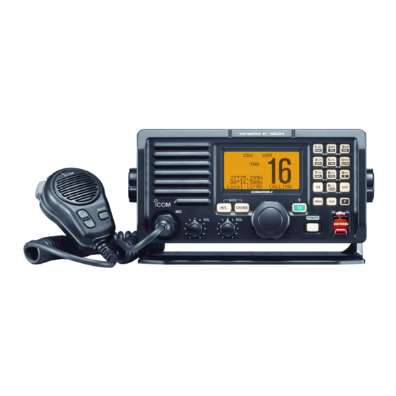
- Page 1 INSTRUCTION MANUAL VHF MARINE TRANSCEIVER iM604...
-
Page 2: Foreword
IC-M604. We want to take a couple of moments of your time to thank you for making the IC-M604 your radio of choice, and hope you agree with Icom’s philosophy of “technology first.” Many EXPLICIT DEFINITIONS hours of research and development went into the design of your IC-M604. -
Page 3: In Case Of Emergency
IN CASE OF EMERGENCY NOTE If your vessel requires assistance, contact other vessels and A WARNING STICKER is supplied with the transceiver. the Coast Guard by sending a Distress call on Channel 16. To comply with FCC regulations, this sticker must be affixed in such a location as to be readily seen from the operating con- USING CHANNEL 16 trols of the radio as in the diagram below. -
Page 4: Radio Operator Warning
RADIO OPERATOR WARNING Icom requires the radio operator to meet the FAILURE TO OBSERVE THESE LIMITS MAY ALLOW FCC requirements for radio frequency exposure. THOSE WITHIN THE MPE RADIUS TO EXPERIENCE RF An omnidirectional antenna with gain not greater RADIATION ABSORPTION WHICH EXCEEDS THE FCC than 9 dBi must be mounted a minimum of 5 me- MAXIMUM PERMISSIBLE EXPOSURE (MPE) LIMIT. -
Page 5: Table Of Contents
TABLE OF CONTENTS I DSC address ID ..............16 FOREWORD ................... i I Position and Time programming .......... 18 IMPORTANT ..................i I Position and Time indication ..........19 EXPLICIT DEFINITIONS ..............i I GPS information indication ..........19 IN CASE OF EMERGENCY ............ii I Distress call ................. -
Page 6: Precautions
Changes or modifications to this device, not ex- BE CAREFUL! The transceiver rear panel will become pressly approved by Icom Inc., could void your authority to hot when operating continuously for long periods. operate this device under FCC regulations. Place the transceiver in a secure place to avoid inadvertent... -
Page 7: Operating Rules
OPERATING RULES D D PRIORITIES (2) OPERATOR’S LICENSE A Restricted Radiotelephone Operator Permit is the license • Read all rules and regulations pertaining to priorities and most often held by small vessel radio operators when a radio keep an up-to-date copy handy. Safety and Distress calls is not required for safety purposes. -
Page 8: Panel Description
PANEL DESCRIPTION I Panel description t POWER KEY [POWER] (p. 9) Speaker Function display (p. 4) ➥ Push to turn power ON. ➥ Push and hold for 1 sec. to turn power OFF. iM604 VHF MARINE y CHANNEL 16/CALL CHANNEL KEY [!6 • 9] ➥... - Page 9 PANEL DESCRIPTION !0 TRANSMIT POWER KEY [H/L] ➥ Number input: ‘2’ ➥ Push to toggle the output power high or low. (p. 9) ➥ Comment input: ‘2,’ ‘A,’ ‘B,’ ‘C’ ‘a,’ ‘b’ or ‘c’ ➥ After pushing [F], push to turn the Tri-watch •...
-
Page 10: I Function Display
PANEL DESCRIPTION I Function display ➥ Number input: ‘7’ ➥ Comment input: ‘7,’ ‘P,’ ‘R,’ ‘S,’ ‘p,’ ‘r’ or ‘s’ ➥ After pushing [F], push to turn the Hailer func- q w e r t tion ON or OFF. (p. 40) ➥... - Page 11 PANEL DESCRIPTION t CHANNEL GROUP INDICATOR (p. 8) !1 POSITION INDICATOR ➥ Shows the GPS position data. Indicates whether an U.S.A. “ ,” International “ ,” Canadian “ ” or weather “ ” channel is in use. • “ ” may blink every 2 sec. instead of position data when the GPS position data is invalid.
-
Page 12: I Microphone
PANEL DESCRIPTION I Microphone Microphone Speaker q PTT SWITCH [PTT] Push and hold to transmit; release to receive. (p. 9) w CHANNEL UP/DOWN KEYS [Y Y ]/[Z Z ] ➥ Push either key to change the operating channels, Set mode settings, etc. (pgs. 7–9, 43) ➥... -
Page 13: Basic Operation
BASIC OPERATION I Channel selection D D Channel 16 D D Channel 9 (Call channel) Channel 16 is the distress and safety channel. It is used for Each regular channel group has a separate leisure-use call establishing initial contact with a station and for emergency channel. - Page 14 BASIC OPERATION D D U.S.A., International and Canadian channels D D Weather channels The IC-M604 is pre-programmed with 59 U.S.A., 59 interna- The IC-M604 has 10 pre-programmed weather channels. tional and 63 Canadian channels. These channel groups may These are used for monitoring broadcasts from NOAA (Na- be specified for the operating area.
-
Page 15: I Receiving And Transmitting
BASIC OPERATION I Receiving and transmitting CAUTION: Transmitting without an antenna will damage Simplex channels, 3, 21, 23, 61, 64, 81, 82 and 83 CANNOT the transceiver. be lawfully used by the general public in U.S.A. waters. q Push [POWER] to turn power ON. IMPORTANT: To maximize the readability of your trans- w Set the audio and squelch levels. -
Page 16: I Call Channel Programming
BASIC OPERATION I Call channel programming I Microphone lock function Call channel is used to select Channel 9 (default), however, The Microphone lock function electrically locks [Y]/[Z] and you can program the call channel with your most often-used [HI/LO] keys on the supplied microphone. This prevents ac- channels in each channel group for quick recall. -
Page 17: I Channel Comments
I AquaQuake water draining function nately. The IC-M604 uses a new technology to clear water away from the speaker grill: AquaQuake. AquaQuake helps drain e Push the appropriate key several times to enter the de- water away from the speaker housing (water that might oth- sired character. -
Page 18: I Optional Voice Scrambler Operation
BASIC OPERATION I Optional Voice scrambler operation D D Activating the scrambler function D D Programming scrambler codes The optional Voice scrambler provides private communica- There are 32 codes (1 to 32) or 128 codes (0 to 127)* avail- tions. In order to receive or send scrambled transmissions you able for programming when an optional scrambler unit is in- must first activate the scrambler function. -
Page 19: Dualwatch/Tri-Watch
DUALWATCH/TRI-WATCH I Description I Operation q Select the desired channel. Dualwatch monitors Channel 16 while you are receiving w Push [F], then push [1• on another channel; Tri-watch monitors Channel 16 and the DUAL ] to start Dualwatch or call channel while receiving another channel. Dualwatch/Tri- [2•... -
Page 20: Scan Operation
SCAN OPERATION I Scan types Scanning is an efficient way to locate signals quickly over a Set the TAG channels (scanned channel) before scanning. wide frequency range. The transceiver has Priority scan and Clear the TAG channels which inconveniently stop scanning, Normal scan. -
Page 21: I Setting Tag Channels
SCAN OPERATION I Setting TAG channels I Starting a scan For more efficient scanning, add the desired channels as TAG Set scan type (Priority or Normal scan) and scan resume channels or clear the TAG for unwanted channels. timer in advance using Set mode. (p. 43) Channels that are not tagged will be skipped during scanning. -
Page 22: Dsc Operation
DSC OPERATION I MMSI code programming I DSC address ID The 9-digit MMSI (Maritime Mobile Service Identity: DSC self A total of 100 DSC address IDs can be programmed and ID) code can be programmed at power ON. named with up to 10 characters. D D Programming Individual ID This code programming can be performed only twice. - Page 23 DSC OPERATION D D Deleting Individual ID q Enter “ ” in DSC Set up menu. ➪ ➪ (Push [MENU]) (Rotate [SELECTOR], then push [ENT].) • When no address ID is programmed, “ ” is displayed. Push [CLR] to exit.
-
Page 24: I Position And Time Programming
DSC OPERATION I Position and Time programming A Distress call should include the ship’s position and time data. If no GPS is connected, your position and UTC (Univer- sal Time Coordinated) time should be input manually. They are included automatically when a GPS receiver (NMEA0183 ver. -
Page 25: I Position And Time Indication
Push for 1 sec. A GPS receiver appropriate for the IC-M604 is not supplied from Icom. A GPS receiver with NMEA0183 ver. 2.0 or 3.01 format is required for position and time indication. Ask your dealer about suitable GPS receivers. -
Page 26: I Distress Call
DSC OPERATION I Distress call e After transmitting the call, the transceiver waits for an ac- A Distress call should be transmitted if, in the opinion of the Master, the ship or a person is in distress and requires imme- knowledgment call on Channel 70. - Page 27 DSC OPERATION D D Regular call r After receiving the acknowledgment, reply using the mi- crophone. The nature of the Distress call should be included in the Dis- tress call. q Enter “ ” in DSC menu. ➪ ...
- Page 28 DSC OPERATION e The position information appears. Edit your position (lati- t Push [DISTRESS] for 5 sec. to transmit the Distress call. tude and longitude) data directly with the keypad. • While pushing [DISTRESS], the key backlighting blinks. • The selected nature of the distress is stored for 10 minutes. •...
-
Page 29: I Transmitting Dsc Calls
DSC OPERATION I Transmitting DSC calls u After receiving the acknowledgment, reply using the mi- crophone. To ensure correct operation of the DSC function, please make sure you set the squelch correctly. (p. 9) D D Transmitting an Individual call The Individual call function allows you to transmit a DSC sig- nal to a specific ship only. - Page 30 DSC OPERATION e Rotate [SELECTOR] to select a desired intership channel y When the acknowledgement ‘Able to comply’ is received, the specified channel (in step e) is selected with beeps or “ ,” push [ENT]. • Intership channels are already preset into the transceiver in rec- automatically.
- Page 31 DSC OPERATION D D Transmitting an Individual Acknowledgement e Rotate [SELECTOR] to select “ ” or When receiving an Individual call, you can transmit an ac- “ ,” push [ENT]. knowledgement (‘Able to comply’ or ‘Unable to comply’) by • When “ ,”...
- Page 32 DSC OPERATION D D Transmitting a Group call The Group call function allows you to transmit a DSC signal to a specific group only. q Enter “ ” in DSC menu. ➪ (Push [MENU]) (Rotate [SELECTOR], then push [ENT].) w Rotate [SELECTOR] to select the desired pre-pro- grammed group address or “...
- Page 33 DSC OPERATION D D Transmitting an All Ships call e Push [ENT] to transmit the All ships call. Large ships use Channel 70 as their ‘listening channel.’ When • Channel 70 is selected and the All ships call is transmitted. you want to announce a message to all ships within range, r After the All ships call has been transmitted, the following use the ‘All Ships Call’...
-
Page 34: D Transmitting A Position Request Call
DSC OPERATION D D Transmitting a Position Request call r After the Position Request call has been transmitted, the Transmit a Position Request call when you want to know a following indication is displayed. specific ship’s current position, etc. q Enter “ ”... - Page 35 DSC OPERATION D D Transmitting a Position Report call e The position information appears. Edit your position data Transmit a Position Report call when you want to announce (latitude and longitude) directly with the keypad. (p. 18) your own position to a specific ship and to get an answer, etc. r After editing the position data, push [ENT] to set.
- Page 36 DSC OPERATION D D Transmitting a Polling Request call e Push [ENT] to transmit the Polling Request call. Transmit a Polling Request call when you want to know a r After the Polling Request call has been transmitted, the fol- specific vessel is within communication range.
- Page 37 DSC OPERATION D D Transmitting a Position Reply call D D Transmitting a Position Report Reply call Transmit a Position Reply call when a Position Request call is Transmit a Position Report Reply call when a Position Report received. call is received. q Enter “...
-
Page 38: I Receiving Dsc Calls
DSC OPERATION I Receiving DSC calls D D Receiving a Distress Acknowledgement While monitoring Channel 70 and a Distress acknowledge- D D Receiving a Distress call ment to other ship is received: ➥ The emergency alarm sounds for 2 minutes. While monitoring Channel 70 and a distress call is received: ➥... - Page 39 DSC OPERATION D D Receiving an Individual call While monitoring Channel 70 and an Individual call is re- ceived: ➥ The emergency alarm or beeps sound depending on the received category. ➥ “ ” appears in the display. ➥ Push [CLR] to stop beep, then push [ENT] to reply the call and select the channel specified by the calling station for D D Receiving an All Ships call voice communication (depending on your replying condi-...
- Page 40 DSC OPERATION D D Receiving a Geographical Area call D D Receiving a Position Request call While monitoring Channel 70 and a Geographical Area call While monitoring Channel 70 and a Position Request call is (for the area you are in) is received: received: ➥...
- Page 41 DSC OPERATION D D Receiving a Polling Request call D D Receiving a Position Report Reply call While monitoring Channel 70 and a Polling Request call is re- While monitoring Channel 70 and a Position Report Reply call ceived: is received: ➥...
-
Page 42: I Received Messages
DSC OPERATION I Received messages D D Other messages The transceiver automatically stores up to 20 distress mes- q Enter “ sages and 20 other messages. The messages can be used ” in DSC menu. as an assistance to the logbook. ... -
Page 43: I Dsc Set Mode
DSC OPERATION I DSC Set mode D D Add Individual ID/Group ID D D Automatic Acknowledgement (See pgs. 16, 17) D D Delete Individual ID/Group ID This item sets the automatic acknowledgement function to (See p. 17) ON or OFF. When a position request, position report or polling request call D D MMSI Code Check is received, the transceiver automatically transmits a position... - Page 44 DSC OPERATION D D Offset Time D D NMEA Output This item sets the offset time from the UTC (Universal Time Select an NMEA Output function from List Station, All Station Coordinated) time. or OFF. When receiving position acknowledgment, the transceiver q Enter “...
-
Page 45: Other Functions
” or “ ” appears on the HM-157. • “ ” appears on the IC-M604 or HM-162 if it is idle. When the connected COMMANDMIC™ is one, step w • To adjust the IC-M604’s speaker output level, rotate [VOL]. does not appear. Go to step e. -
Page 46: I Hailer Operation
To return to normal operation, push [CLR] or repeat step The IC-M604 has a 2-way hailer function for voice amplifica- tion and reception over a loudspeaker, making it unnecessary to leave the bridge to hear a hailing party. During hailer oper- •... -
Page 47: I Automatic Foghorn
OTHER FUNCTIONS I Automatic foghorn The automatic foghorn function sounds a horn repeatedly The foghorn outputs from the hailer speaker. To use this func- until the function is turned OFF. Four patterns are available tion, the hailer speaker must be connected to the transceiver. for varying conditions. -
Page 48: I Rx Speaker Function
I RX speaker function q Push [F], then push [8• ] to enter auto foghorn mode. The IC-M604 has an RX speaker function. When this func- Push tion is turned ON, the received audio can be heard on the then push deck or tower via a hailer speaker. -
Page 49: Set Mode
SET MODE I Set mode programming I Set mode items D D Scan type Set mode is used to change the conditions of the trans- ceiver’s functions: Scan type, Scan resume timer, Weather The transceiver has 2 scan types: normal scan and priority alert, Beep tone, Internal speaker, LCD contrast, Attenuation scan. - Page 50 SET MODE D D Weather alert A NOAA broadcast station transmits a weather alert tone be- (Default: ON) fore important weather information. When “ ” is selected, the previously selected (used) weather channel is checked any time during standby or while scanning. When “ D D LCD contrast ”...
- Page 51 SET MODE D D Scrambler code (Appears when a scrambler unit is installed) When an optional scrambler unit is installed, the scrambler (Default: 400) code can be set depending on dealer setting. When the UT-112 is installed, 32 codes (1 to 32) can be se- lected.
-
Page 52: Connections And Maintenance
CONNECTIONS AND MAINTENANCE I Connections r EXTERNAL MICROPHONE CONNECTORS [COMMAND MIC-1]/[COMMAND MIC-2] Connects the optional COMMANDMIC™ (HM-157/HM- 162.) CAUTION: NEVER connect other microphone here, such as the HM-134, may cause damage to the trans- ceiver. t GPS RECEIVER/EXTERNAL SPEAKER CONNECTOR ➥... -
Page 53: I Fuse Replacement
CONNECTIONS AND MAINTENANCE I Supplied accessories y DC POWER CONNECTOR The following accessories are supplied Connects the supplied DC power cable from this connector to an external 13.8 V DC power source. Mounting bracket For mounting bracket CAUTION: After connecting the DC power cable, cover Knob bolts Flat washers (M5) the connectors with a rubber vulcanising tape as shown... -
Page 54: I Mounting The Transceiver
CONNECTIONS AND MAINTENANCE I Mounting the transceiver D D Using the supplied mounting bracket • OVERHEAD MOUNTING The universal mounting bracket supplied with your transceiver allows overhead or onboard mounting. Sponge* • Mount the transceiver securely with the 4 supplied screws 20) to a surface which is more than 10 mm thick and can support more than 5 kg. -
Page 55: I Mb-75 Installation
FLUSH MOUNT KIT the transceiver to a flat surface such as an instrument panel. • Make sure that the clamps align parallel to the IC-M604’s body. CAUTION: KEEP the transceiver and microphone at least 1 meter away from your vessel’s magnetic navigation com- pass. -
Page 56: I Optional Unit Installation
CONNECTIONS AND MAINTENANCE I Optional unit installation w Turn the transceiver upside down, then disconnect the flat CAUTION: DISCONNECT the DC power cable from the transceiver before performing any work on the transceiver. cables and Rear mic control (6-pin) from LOGIC board, Otherwise, there is danger of electric shock and/or equip- and Front mic control (2-pin) and Volume control (3-pin) ment damage. -
Page 57: I Hm-157/Hm-162 Installation
CONNECTIONS AND MAINTENANCE I HM-157/HM-162 installation e Install an optional unit to J3 on the AF board as shown below. Optional unit AF board HM-157 HM-162 The optional HM-157 can be connected to the transceiver di- rectly, as well as via the supplied connection cable for longer r Assemble the units to their original positions. - Page 58 CONNECTIONS AND MAINTENANCE q Insert the supplied cable (or HM-157 without the cable) t Install the mounting base using the supplied screws as into the [COMMAND MIC-1] or [COMMAND MIC-2] con- shown below. nector and tighten the cable nut as shown below. •...
- Page 59 CONNECTIONS AND MAINTENANCE HM-162 HM-157 Mounting base Mounting base Gasket Gasket...
-
Page 60: Troubleshooting
TROUBLESHOOTING PROBLEM POSSIBLE CAUSE SOLUTION REF. The transceiver does • Bad connection to the power supply. • Check the connection to the transceiver. pgs. 46, not turn ON. No sound from speaker. • Squelch level is too high. • Set [SQL] to the threshold point. p. -
Page 61: Specifications And Options
SPECIFICATIONS AND OPTIONS I Specifications D D General D D Receiver • Frequency coverage : TX 156.025–157.425 MHz • Receive system : Double conversion superheterodyne RX 156.050–163.275 MHz • Sensitivity (12 dB SINAD) : 0.22 µV (typical) • Mode : FM (16K0G3E), DSC (16K0G2B) 0.22 µV (typical) (CH 70 receiver) •... -
Page 62: I Options
SPECIFICATIONS AND OPTIONS I Options D D Dimensions • MB-75 FLUSH MOUNT KIT For mounting the transceiver to a panel. • HM-157 ™ COMMANDMICII External microphone-type controller. Provides optional inter- com operation. 6 m (20 feet) microphone cable and mount- ing base included. -
Page 63: Channel List
CHANNEL LIST Channel number Frequency (MHz) Channel number Frequency (MHz) Channel number Frequency (MHz) Channel number Frequency (MHz) CAN Transmit Receive CAN Transmit Receive CAN Transmit Receive CAN Transmit Receive 156.050 160.650 157.050 161.650 156.425 156.425 157.325 157.325 156.050 156.050 21A 157.050 157.050 156.475 156.475 157.375 161.975... - Page 64 A-6527D-1US-q Printed in Japan 1-1-32 Kamiminami, Hirano-ku, Osaka 547-0003, Japan 2006 Icom Inc. ©...