Table of Contents
Advertisement
Quick Links
Advertisement
Table of Contents

Related Manuals for Vivax ACP-09PT25AEB


Summary of Contents for Vivax ACP-09PT25AEB
- Page 1 Service manual ACP-09PT25AEB RoHS NNO-1/09...
-
Page 3: Table Of Contents
Content CONTENT Safety precaution .....................1 Installation ........................... 1 Caution..........................1 Operational.......................... 1 Out dimension ......................3 Display........................5 LED display .........................5 LCD display .........................5 Refrigerant cycle diagram ..................6 PCB drawing & wiring diagram ................7 9K Model ..........................7 12K Model ..........................7 Installation detail ......................8 Position requirement for installation .................. -
Page 4: Safety Precaution
Safety Precaution Safety precaution Installation For electrical work, contact the dealer, seller, a qualified electrician, or an Authorized service center. Do not disassemble or repair the product by yourself. Sharp edges could cause injury, be especially careful of the case edges and the fins on the condenser and evaporator. - Page 5 Safety Precaution Do not insert hands or other object through air inlet or outlet while the product is operated. Do not drink the water drained from the product. Use a firm stool or ladder when cleaning or maintaining the product. Replace the all batteries in the remote control with new ones of the same type.
-
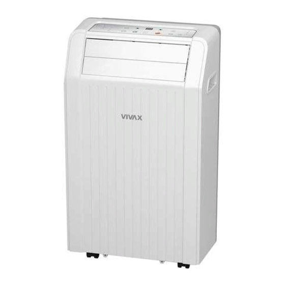
Page 6: Out Dimension
Outer dimension Out dimension Model: ACP-09PT25AEB... -
Page 7: Display
External view, part, display Display Rem ote signal rec eptor (The model has no (Some m ode ls ha ve t he sig nal receptor on th e auto swing feature fro nt panel , Fi g.2) wit hou t t his butt on) Fig.4 ) and DOWN( ) button... -
Page 8: Refrigerant Cycle Diagram
Refrigerant cycle diagram Refrigerant cycle diagram The figure below is a brief description of the important components and their function in what is called the refrigeration system... -
Page 9: Pcb Drawing & Wiring Diagram
PCB drawing & Wiring diagram PCB drawing & wiring diagram 8K/9K12K Model DISPLAY BOARD AMBIENT SENSOR EVAPORATOR SENSOR DOWN FAN P I PE S E N SO R BLACK SWING YELL OW CN10 BLUE BROWN OPT IONA L UP FAN CN11 BLACK MOTOR... -
Page 10: Installation Detail
Feature Installation detail Position requirement for installation Installation must be in a flat and spacious location where the air outlets will not be covered up. A minimum clearance of 30cm from a wall or other obstacles should be kept. The appliance shall not be used in the washroom. -
Page 11: Installation In A Double-Hung Sash Windows
Feature Installation in a double-hung sash windows 6.3.1 Cut the foam seal (adhesive type) to the proper length and attach it to the window stool. 6.3.2 Attach the window panel to the window stool. Adjust the length of the window panel according to the width of window, short the adjustable panel if the width of window is less than 26”. -
Page 12: Installation In A Sliding Sash Windows
Feature Installation in a sliding sash windows 6.4.1 Cut the foam seal to a proper length and adhesive to the window frame. 6.4.2 Attach the window panel to the window stool. Adjust the length of the sliding window panel according to the width of window, short the adjustable panel if the width of window is less than 26”. - Page 13 Feature 6.4.4 Close the sliding sash securely against the window. 6.4.5 Cut the foam seal to an appropriate length and sealing the open gap between the top window sash and outer window sash. Show as below picture.
-
Page 14: Features
Feature Features single louver flat appearance,Simple and generous Straight condenser ,low cost、 High efficiency Turbo cooling function Flexible air exhaust Advanced shower system Follow me function 24 hour on/off Cooling Double louver flat appearance,Simple and generous Straight condenser ,low cost、 High-efficiency Turbo cooling function Flexible air exhaust... -
Page 15: Basic Test Procedure
Basic test procedure Basic test procedure Defective compressor Compressors are single phase, 115 or 230/208 volt, depending on the model unit. All compressor motors are permanent split capacitor type using only a running capacitor across the start and run terminal. All compressors are internally spring mounted and externally mounted on rubber isolators. -
Page 16: Sealed Refrigeration System Repairs
Basic test procedure 3. Start the system and run a “cooling or heating performance test.” If test shows: A. Below normal high side pressure. B. Above normal low side pressure. C. Low temperature difference across coil. The compressor valves are faulty - replace the compressor. 8.1.4 Terminal overload (external) Some compressors are equipped with an external overload which is located in the... - Page 17 Basic test procedure 4. E.P.A. Approved Refrigerant Recovery System. 5. Vacuum Pump (capable of 200 microns or less vacuum.) 6. Acetylene Welder 7. Electronic Halogen Leak Detector (G.E. Type H-6 or equivalent.) 8. Accurate refrigerant charge measuring device such as: a.
-
Page 18: Fan Motor
Basic test procedure refrigerant specified. This will prevent boiling the oil out of the crankcase. NOTE: If the entire charge will not enter the high side, allow the remainder to enter the low side in small increments while operating the unit. 12. -
Page 19: Capacitor
Basic test procedure 3. Apply "live" test cord probes on black wire and common terminal of capacitor. Motor should run at high speed. 4. Apply "live" test cord probes on red wire and common terminal of capacitor. Motor should run at low speed. 5. -
Page 20: Characteristic Of Temperature Sensor
Characteristic of temperature sensor Characteristic of temperature sensor Resistance Resistance Resistance Temp.℃ Temp.℃ Temp.℃ KΩ KΩ KΩ 62.2756 14.6181 4.3874 58.7079 13.918 4.2126 56.3694 13.2631 4.0459 52.2438 12.6431 3.8867 49.3161 12.0561 3.7348 46.5725 11.5 3.5896 10.9731 3.451 41.5878 10.4736 3.3185 39.8239 3.1918 37.1988... -
Page 21: Trouble Shooting
Trouble shooting Trouble shooting PROBLEM POSSIBLE CAUSE REMEDY Check the power supplier if the power supplier is supplied Power failure to the unit. Check the power cord and correct if damaged. No power display Transformer (Discharge Check resistance between the two input/output lines on on panel or any transformer before transformer. - Page 22 Trouble shooting Loose screws Tighten them. Replace the motor if knocking sounds continue when Worn bearings running or loose, or the motor hums or noise appears to be internal while running. Voltage Check voltage. Call Supply Authority if not within limits. Check the wire connections, if loose, repair or replace the terminal.
- Page 23 Trouble shooting The inlet and outlet valve of the compressor is damaged, making the low pressure connected with the high pressure. Compressor The refrigerating system can not produce high pressure and low pressure. Replace the compressor after checking for the reason. Heat sources Reduce if too many.