Barco HDX User And Installation Manual
Hdx series
Hide thumbs
Also See for HDX:
- Installation manual (351 pages) ,
- User and installation manual (331 pages)

Related Manuals for Barco HDX


Summary of Contents for Barco HDX
- Page 1 HDX series User and Installation manual For HDX, HDX W12, HDX W14,HDX W18 and HDX W20 R5905032/12 20/11/2014...
- Page 2 Product revision Software version: 1.8. Barco nv Noordlaan 5, B-8520 Kuurne Phone: +32 56.36.82.11 Fax: +32 56.36.883.86 Support: www.barco.com/esupport Visit us at the web: www.barco.com Printed in Belgium...
- Page 3 GNU-GPL code If you would like a copy of the GPL source code contained in this product shipped to you on CD, please contact Barco. The cost of preparing and mailing a CD will be charged. Guarantee and Compensation Barco provides a guarantee relating to perfect manufacturing as part of the legally stipulated terms of guarantee.
- Page 4 Barco. If the purchaser or a third party carries out modifications or repairs on goods delivered by Barco, or if the goods are handled incorrectly, in particular if the systems are operated incorrectly or if, after the transfer of risks, the goods are subject to influences not agreed upon in the contract, all guarantee claims of the purchaser will be rendered invalid.
-
Page 5: Table Of Contents
Help information in adjustment mode ....................74 R5905032 HDX SERIES 20/11/2014... - Page 6 10.4.4 PiP window, Size ......................142 R5905032 HDX SERIES 20/11/2014...
- Page 7 12.15.3 3D Sync Loop Through ..................... .217 R5905032 HDX SERIES 20/11/2014...
- Page 8 15.2 Cleaning the exterior of the projector ....................291 R5905032 HDX SERIES 20/11/2014...
- Page 9 E. Stacking HDX projectors ............... ..
- Page 10 Table of contents R5905032 HDX SERIES 20/11/2014...
-
Page 11: Safety
Read this chapter attentively. It contains important information to prevent personal injury while installing and using a HDX projector. Furthermore, it includes several cautions to prevent damage to the HDX projector. Ensure that you understand and follow all safety guidelines, safety instructions and warnings mentioned in this chapter before installing your HDX projector. After this chapter, addi- tional “warnings”... -
Page 12: Important Safety Instructions
fixed wiring. • Never stack more than two (2) HDX projectors in a hanging configuration (truss) and never stack more than three (3) HDX projectors in a base stand configuration (table mount). - Page 13 fire extinguishers. Never use water on an electrical fire. Always have service performed on this projector by authorized Barco service personnel. Always insist on genuine Barco replacement parts. Never use non-Barco replacement parts as they may degrade the safety of this projector.
-
Page 14: Important Warnings Concerning Hdx Flight Cases
If the product exhibits a distinct change in performance, indicating a need for service. • Replacement parts: When replacement parts are required, be sure the service technician has used original Barco replacement parts or authorized replacement parts which have the same characteristics as the Barco original part. Unauthorized substitu- tions may result in degraded performance and reliability, fire, electric shock or other hazards. - Page 15 1. Safety • Use an appropriate forklift to raise flight cases and take the necessary precautions to avoid personnel injury. R5905032 HDX SERIES 20/11/2014...
- Page 16 1. Safety R5905032 HDX SERIES 20/11/2014...
-
Page 17: General
2. GENERAL About this chapter Read this chapter before installing your HDX projector. It contains important information concerning installation requirements for the HDX projector, such as minimum and maximum allowed ambient temperature, humidity conditions, required safety area around the installed projector, required power net, etc. -
Page 18: Projector Weight
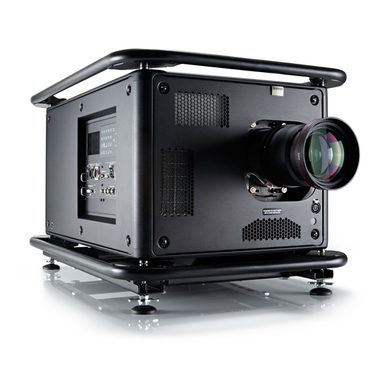
Projector weight Do not underestimate the weight of the HDX projector. The projector weights about ±50 kg (±111 lb.) without lens. Be sure that the pedestal on which the projector has to be installed is capable of handling five (5) times the complete load of the system. -
Page 19: Initial Inspection
Save all packing material until the inspection is completed. If damage is found, file claim with carrier immediately. The Barco Sales and Service office should be notified as soon as possible. -
Page 20: Hdx Flight Case
The HDX flight case is designed to transport the HDX projector in a safe and secure manner. The four caster wheels, provided with breaks, and the four handles make the HDX flight case easy to handle. The floor of the flight case wagon is equipped with two small covered compartments to store the remote control and the rigging clamps. -
Page 21: Rear Projection
Front projection, Ceiling mounted, in table position Rear projection The projector is installed, either in a table mount or ceiling mount configuration, at the other side of the screen opposite the audience. AUDIENCE BACKSTAGE FLOOR Image 2-6 Rear projection R5905032 HDX SERIES 20/11/2014... -
Page 22: Positioning The Projector
Off-Axis projection is obtained by shifting the lens up, down, left or right. Several parameters can be calculated determining the position in any installation. Formula to calculate the distance CD for On-Axis projection: CD = SH/2 + B - A R5905032 HDX SERIES 20/11/2014... - Page 23 Side to side tilt, however, must not exceed ±15°. This limit ensures that the lamp in the projector operates properly and safely. More tilting within area C is allowed but lamp flicker can happen. 360° 15° 15° 15° 15° Image 2-10 Tilting allowed without problems No tilting allowed in this area R5905032 HDX SERIES 20/11/2014...
-
Page 24: Projector Air Inlets And Outlets
Air inlets and outlets Image 2-11 The HDX projector has 3 air inlet channels and 3 air outlets. The air outlets are located at the rear of the projector. The air inlets are located at the front of the projector. -
Page 25: Installation Process Overview
Installation process overview Quick setup The following steps describe briefly how to setup your HDX projector in a table mount front projection. Note that each step refers to a corresponding procedure, which is more detailed and illustrated. 1. Install the batteries of the remote control. See "RCU battery installation", page 23 2. - Page 26 2. General R5905032 HDX SERIES 20/11/2014...
-
Page 27: Physical Installation
Introduction The remote control unit (A) of the HDX projector is equipped with a rugged case (B) and an XLR adaptor (C). The remote control unit can be used wired via mini-jack or via rugged XLR. Note that the backlight, of the remote control unit, illuminate continuously when wire connected. -
Page 28: Rcu Rugged Case Installation
How to install the rugged case of the remote control ? 1. Slide the bottom of the RCU into the rugged case and then pull the top of the rugged case over the top of the RCU as illustrated. R5905032 HDX SERIES 20/11/2014... -
Page 29: Rcu Xlr Adaptor Installation
1. Connect a cable with XLR plug into the XLR adaptor. 2. Connect the other end of the cable with your HDX projector. 3. Push the XLR adaptor completely against the rugged case of the remote control unit, as illustrated in the left image below, for wired communication. -
Page 30: Rcu Usage Possibilities
RCU with rugged case and XLR adaptor The RCU will send the commands via the cable connected with the XLR pushed in “WIRED” and wired adaptor to the projector. Backlight illuminates continuously when wire is connected. Infra red disabled. Image 3-8 R5905032 HDX SERIES 20/11/2014... -
Page 31: Lenses
Scheimpflug adjustment 3.2.1 Available lenses Available lenses for the HDX projector projector The TLD HB (High Brightness) lens series can be used on the HDX projector projector. Image 3-9 Image 3-10 Image 3-11 R9852000: TLD HB fixed lens (0.8 : 1) R9840770: TLD fixed lens (1.2 : 1) -
Page 32: Lens Selection
How to select the right lens 1. Determine the required screen width (SW). 2. Determine the approximate position of the projector in the room. 3. Start up the Lens Calculator on the Barco website: http://www.barco.com/en/tools/lenscalculator to determine the possible lenses for your configuration. -
Page 33: Lens Installation
4. Ensure that the lens holder stands in the On-Axis position (horizontal and vertical mid position). Note: The lens holder is placed default in the On-Axis position at factory. 5. Gently insert the lens in such a way that the lens connector matches the socket (B). R5905032 HDX SERIES 20/11/2014... -
Page 34: Lens Removal
Neglecting this can damage the Lens Holder and Prism. 3.2.4 Lens removal How to remove 1. Support the lens with one hand while you unlock the lens holder by sliding the lock handle towards the “unlocked” position as illustrated. Image 3-27 Lens removal, unlock R5905032 HDX SERIES 20/11/2014... -
Page 35: Lens Safety Cable
The lens safety cable must be used in any circumstances to protect a mounted lens in the lens holder when the projector is mounted above persons. Necessary parts Safety cable: R9801079 (Barco order number) How to mount the cable 1. Put the safety cable around the lens. Make sure the cable is mounted between the motor part and the mounting flange... - Page 36 Secure the cable by fixating the nut of the clamp. Image 3-30 Clamp position 3. Turn the cable with hook lock around the carry handle and hook the hook lock around the cable. R5905032 HDX SERIES 20/11/2014...
-
Page 37: Lens Shift, Zoom & Focus
The zoom/focus menu opens. Image 3-32 Zoom/Focus adjustment 2. Use the ▲ or ▼ key to zoom the lens. Use the ◄ or ► key to focus the lens. Press ENTER to switch to Lens shift adjustment. R5905032 HDX SERIES 20/11/2014... -
Page 38: Scheimpflug Adjustment
DMD plane, the plane of sharp focus will also be tilted according to geometrical and optical properties. The DMD plane, the principal lens plane and the sharp focus plane will intersect in a line below the projector for downward lens tilt. R5905032 HDX SERIES 20/11/2014... -
Page 39: How To Adjust
2. Loosen the lock nuts (a, b, c and d). See image 3-35. 3. Loosen the 4 set screws (A, B, C and D) by 1 cm. See image 3-35. 4. Fully loosen lock nut 4. See image 3-35. R5905032 HDX SERIES 20/11/2014... - Page 40 Repeat steps “a” and “b” until the projected image is as sharp as possible. Image 3-37 Center focusing 6. Sharpen bottom left corner of the screen by adjusting nut 1. Image 3-38 Left bottom focusing 7. Sharpen bottom right corner of the screen by adjusting nut 2. R5905032 HDX SERIES 20/11/2014...
- Page 41 Any movement of the image will affect the Scheimpflug adjustment 2. Fasten lock nuts a, b and c. 3. Turn in set screw D lightly (by hand) allowing the image to move slightly (1/3 to 1/2 of a square). R5905032 HDX SERIES 20/11/2014...
-
Page 42: Connecting The Projector With The Power Net
1. Ensure that the power switch stands in the ’0’ (OFF) position (1). Image 3-42 Power input 2. Connect the female side of the power cord with the power input socket of the projector (2). 3. Secure the power plug by locking the plug holder clamp (3). R5905032 HDX SERIES 20/11/2014... -
Page 43: Alignment Of A Table Mounted Projector
When this is achieved, the projector is set horizontal and vertical at right angles to the screen. Image 3-44 Angle adjustment Mounting the bottom carry handler Necessary tools Open wrench 17 mm Necessary parts 4x bolt M10 x 16 mm R5905032 HDX SERIES 20/11/2014... - Page 44 4. Place the carry handle on the projector as illustrated. Adjustment knob to the back of the projector. Make sure that the mounting holes matches the holes in the projector. 5. Insert a bolt in each corner and turn in these bolts. R5905032 HDX SERIES 20/11/2014...
-
Page 45: Mounting The Top Carry Handler
1. Place the carry handle on top of the projector so that the fixation holes match the holes in the projector. Image 3-48 top carry handle 2. Turn in the 4 fixation bolts (1). Insert a washer between the bolt and the carry handle. R5905032 HDX SERIES 20/11/2014... -
Page 46: Suspension Of The Projector With Rigging Clamps
To release the nuts of the rigging points use a 24 mm open ended spanner. Ensure that the rigging points are symmetrically lined up, so that the projector will hang in balance. Warning: Be careful while working with heavy loads. Warning: Always secure the rigging points after adjustment. Image 3-51 Rigging points, distance R5905032 HDX SERIES 20/11/2014... - Page 47 5. Place the projector (upside down) under the truss installation and lower the truss until the support bars of the truss are nearby the rigging clamps mounted on the projector. Image 3-53 Mount to truss 6. Lift up the projector and hook the four rigging clamps over the support bars of the truss. R5905032 HDX SERIES 20/11/2014...
-
Page 48: Alignment Of A Ceiling Mounted Projector
20 cm. If necessary, turn the cables a few times around the truss to obtain this maximum distance. Alignment of a ceiling mounted projector Necessary tools 17 mm open spanner Skew adjustment 1. Turn the adjustment knob on the carry handle until the projected hatch pattern is perfectly squared. R5905032 HDX SERIES 20/11/2014... - Page 49 Always adjust by two to avoid deformation of the frame. 2. Loosen the security nut on both clamps. 3. Adjust the adjustment nuts of both clamps until the desired tilting is reached. 4. Turn the safety nut on the rigging clamp against the rigging point R5905032 HDX SERIES 20/11/2014...
- Page 50 3. Physical installation R5905032 HDX SERIES 20/11/2014...
-
Page 51: Input & Communication
XLR input port for remote control RS232/RS422 input port Dual Link DVI-I HDCP input Free input slot Button module Optional antenna for GSM RS232/RS422 input port Ethernet port Status and indication LEDs USB port 3G/Dual/HDSDI input - output Free input slot R5905032 HDX SERIES 20/11/2014... -
Page 52: Input Source Connections
4. Input & Communication Input source connections DVI and 3G/HDSDI input This input module is standard delivered with the HDX projector. R9864000 3G/DUAL HDSDI DUAL LINK DVI-I HDCP SYNC SYNC SYNC OUT1 OUT2 INPUT Image 4-2 Dual Link DVI and 3G/Dual HDSDI input The yellow LED lights up when valid input sync is detected. - Page 53 BNC socket. Generates 3D synchronization signal to drive an infra red transmitter for active 3D glasses. In case an 3D syn- chronization signal is applied on the “3D SYNC IN” for a single channel 3D stream then the generated 3D output sync is derived from this applied sync. Input specifications R5905032 HDX SERIES 20/11/2014...
-
Page 54: Communication Connections
You can use the DMX input port to connect a DMX device (DMX console) to the projector. This way you can control the projector from that DMX device (console). The DMX output port can be connected with the next device in the loop. Description Earth R5905032 HDX SERIES 20/11/2014... - Page 55 The left one a Sub-D connector, the right one an USBB connector acting as RS input when connected to an USB input of a PC. You can use the RS232/RS422 input to connect a local PC to your HDX projector. By this way you can configure and control your HDX projector from your local PC.
-
Page 56: Usb Port
When a 100 MB network is detected IR received but not acknowledged green IR received and acknowledged orange WIFI sel When WiFi is selected green When WiFi is connected with an Ethernet See chapter “Getting started”, topic “Status LEDs” R5905032 HDX SERIES 20/11/2014... -
Page 57: Utility-Accessory Outlet
Power 9 - 24 Volt DC With Setting in menu 9 / 12 / 24 @ 25W Note : do not overload ! Maximum 1A on 24V is allowed. The connector is a duplicated output of the DMX signal entering the projector over the 5 Pin XLR R5905032 HDX SERIES 20/11/2014... - Page 58 4. Input & Communication R5905032 HDX SERIES 20/11/2014...
-
Page 59: Getting Started
• switching to "pause" (blanked picture, full power for immediate restarting) • direct access to all connected sources. Terminology overview Overview The following table gives an overview of the different functionality of the keys. R5905032 HDX SERIES 20/11/2014... - Page 60 Use these buttons to obtain the desired picture level. PHASE Used to remove the horizontal instability of the image (usually for RGB source). It adjusts the phase of the pixel sampling clock relative to the incoming signal. FREEZE To freeze the actual projected image. R5905032 HDX SERIES 20/11/2014...
-
Page 61: Power On Projector
The projector starts up in standby. The menus are accessible via the local LCD panel. The start up screen is displayed on the local LCD panel and when fully started up, it changes to the overview screen. R5905032 HDX SERIES 20/11/2014... - Page 62 The background image of the startup screen and info screens can be changed with Projector Toolset with an installed HDX plug-in. Lamp overview Once the projector is started, press Lamp to get an overview of the lamp parameters such as : Image 5-4 Local screen, lamp R5905032 HDX SERIES 20/11/2014...
-
Page 63: Software Overview
Image 5-5 Local screen, about • Package version • Mgr software • GUI software Starting image projection via the standby key. 1. Press Stand by key once on the local keypad or on the remote control. R5905032 HDX SERIES 20/11/2014... -
Page 64: Switching To Standby
How to power off 1. Press first Standby. 2. Let cool down the projector until the fan speed decreases. At least 5 minutes. 3. Switch off the projector with the power switch. ’0’ must be pressed. R5905032 HDX SERIES 20/11/2014... -
Page 65: Status Leds
LED) Red toggles on/off Error Orange toggles on/off Warning IR signal received Green IR signal acknowledged Using the RCU Pointing to the reflective screen 1. Point the front of the RCU to the reflective screen surface. R5905032 HDX SERIES 20/11/2014... - Page 66 IR sensor. 45° 45° 45° 45° 45° 45° Image 5-8 RCU to one of the IR sensors R5905032 HDX SERIES 20/11/2014...
-
Page 67: Projector Address
Every projector has a common address ’0’ or ’1’. The choice between ’0’ and ’1’ can be selected in Projector Control → Projector address → Common address. Source selection Source selection when no picture in picture is active Use the digit keys on the remote control or local keypad to activate the desired source. R5905032 HDX SERIES 20/11/2014... - Page 68 To select the source for the picture in picture window, press Window button until PiP window is activated and then select the desired source with the digit keys. To select the source for the main window, press Window button until the main window is activated and then select the desired source with the digit keys. R5905032 HDX SERIES 20/11/2014...
-
Page 69: Quick Set Up Adjustment
To toggle Text ON or OFF, press the TEXT key on the remote control or local keypad. Quick Lens Adjustment via LENS key Quick zoom/focus adjustment 1. Press the LENS key on the remote control or local keypad to open the Zoom/Focus Adjustment menu. R5905032 HDX SERIES 20/11/2014... - Page 70 3. When finished, press EXIT key to return or ENTER to continue to the shift adjustment. Press the LENS key to call the list with available test patterns. Quick shift adjustment 1. Press the LENS key on the remote control or local keypad to open the Zoom/Focus Adjustment menu. R5905032 HDX SERIES 20/11/2014...
-
Page 71: Direct Lens Adjustment (Rcu)
On the Remote Control four buttons with double action are provided, allowing direct alignment for lens ZOOM, FOCUS, HORIZON- TAL SHIFT and VERTICAL SHIFT. 1. Press LENS ZOOM button [-] or [+] (A) for correct image size on the screen. R5905032 HDX SERIES 20/11/2014... -
Page 72: Quick Picture In Picture
Select Main full screen to switch off PIP. Image 6-7 Load layout file list Quick language selection Quick language selection via the remote control When no OSD menu is visible on the screen, press the Info button (1) on the remote control. R5905032 HDX SERIES 20/11/2014... - Page 73 1. Press Menu to activate the menus and select Projector Control → Change Language. 2. Press ENTER to open the language selection menu. 3. Select the desired language with the ▲ ▼ key and press ENTER to activate. The current active language is indicated with a selected radio button R5905032 HDX SERIES 20/11/2014...
- Page 74 6. Quick set up adjustment Image 6-10 Main menu Image 6-11 Projector Control Image 6-12 Change language R5905032 HDX SERIES 20/11/2014...
-
Page 75: Start Up Of The Adjustment Mode
To start up the adjustment mode, use the remote control or the local keypad. How to start up? 1. Press Menu on the remote control (RCU) or on the local keypad to start up the Adjustment mode. R5905032 HDX SERIES 20/11/2014... -
Page 76: Navigation And Adjustments
Image 7-2 Use the ◄ or ► key to directly adjust the current value. Via bar scale adjustment : Once an item is selected, press ENTER to open the bar scale menu. Image 7-3 Contrast adjustment R5905032 HDX SERIES 20/11/2014... -
Page 77: Menu Memory
Scroll to the desired menu. Press the digit key behind which the menu must be stored for 5 seconds. When the creation is success- fully, a confirmation message appears on the screen. E.g. : Image 7-5 Select Yes to confirm the creation. To erase the shortcut, navigate to Projector Control → Buttons. R5905032 HDX SERIES 20/11/2014... -
Page 78: Test Patterns In Adjustment Mode
MENU EXIT ENTER Image 7-7 Info button When no information is available for the selected item, the message No help available for this item is displayed. To return to the adjustment mode, press EXIT. R5905032 HDX SERIES 20/11/2014... -
Page 79: Input
Input 2 DUAL SDI Input Locking Input on Main Window Input on Pip Window Input 1 Input 2 Input 3 Input 4 Free Run Free Run Options Minimum delay Native Resolution [On/Off] No Signal Color [black/blue] R5905032 HDX SERIES 20/11/2014... -
Page 80: Input Selection
1. Press Menu to activate the menus and select Input → Input Selection. 2. Press ENTER. The Select Source menu is displayed with the actual available sources filled out. 3. Use the ▲ or ▼ key to select an input. Image 8-1 Main window Image 8-2 Input selection R5905032 HDX SERIES 20/11/2014... -
Page 81: Advanced Settings
3. Use the ▲ or ▼ key to select an input Press ENTER to open the selection menu which will be different from input type to input type. Image 8-4 Main window Image 8-5 Advanced input settings R5905032 HDX SERIES 20/11/2014... -
Page 82: Dvi - Rgb Input
AUTO mode, then the Color Space must be selected as no automatic detection is possible. Use the ▲ or ▼ key to select the correct color space and press ENTER to select. Image 8-8 Color space selection for AUTO R5905032 HDX SERIES 20/11/2014... -
Page 83: Sdi Input
4:4:4 - YCbCr-10 • 4:4:4 - RGB-10 • 4:2:2 - YCbCr-12 • 4:4:4 - YCbCr-12 • 4:4:4 - RGB-12 Then, select the 3G setting. Use the ▲ or ▼ key to select and press ENTER to accept. R5905032 HDX SERIES 20/11/2014... -
Page 84: Cable Input
HDMI - DisplayPort input (3D input module) How to select Select HDMI/DP and press ENTER to open the selections Image 8-13 HDMI-Display port selection Use the ▲ or ▼ key to select the desired input and press ENTER to select. R5905032 HDX SERIES 20/11/2014... -
Page 85: Input Locking
Output is locked on input 2 Input 3 Output is locked on input 3 Input 4 Output is locked on input 4 Free run Output is locked on an internal sync (60 Hz or manual setup) R5905032 HDX SERIES 20/11/2014... -
Page 86: Minimum Delay
To ensure minimum delay in the other processing steps, make sure warping is OFF, the resolution of the input source is native and the input locking is set to the main input. How to toggle the delay 1. Press Menu to activate the menus and select Input → Minimum delay [On]. R5905032 HDX SERIES 20/11/2014... -
Page 87: Native Resolution
When the show native resolution function is in the ON position, the projector handles the source as follows: Source Projected image Name Ratio Resolution Ratio Resolution 1024x768 1024x768 image projected with black borders SXGA 1280x1024 1280x1024 image projected with black borders SXGA+ 1400x1050 1400x1050 image projected with black borders R5905032 HDX SERIES 20/11/2014... -
Page 88: No Signal
8.7.1 Background color How to set the background color 1. Press Menu to activate the menus and select Input → No Signal. → Color. 2. Press ENTER to toggle between [Blue] or [black]. R5905032 HDX SERIES 20/11/2014... -
Page 89: Background Logo
How to activate logo 1. Press Menu to activate the menus and select Input → No Signal. → Logo. 2. Press ENTER to toggle between [On] or [Off]. Image 8-27 Main window Image 8-28 Input, no signal R5905032 HDX SERIES 20/11/2014... -
Page 90: Shutdown Settings
8. Input Image 8-29 No signal, logo A dedicated logo can be loaded via Projector Toolset with a HDX plug-in installed. 8.7.3 Shutdown settings How to change the settings 1. Press Menu to activate the menus and select Input → No Signal. → Shutdown. -
Page 91: Auto Dimming
How to set up 1. Press Menu to activate the menus and select Input → No Signal. → Auto Dimming. Image 8-36 Main window Image 8-37 Input, no signal R5905032 HDX SERIES 20/11/2014... -
Page 92: Edid
EDID file. The selection of the EDID file to be used is made in the Configure menu. Making your own custom EDID file(s) is done through Create. Custom EDID files can be deleted at any time. The Standard EDID includes two timings: 1920x1200@60Hz / 1920x1080@60Hz (for HDX, HDF and APOLLO projectors) and 2048x1080@60Hz / 1920x1080@60Hz (for HDQ projectors). - Page 93 Your selection is applied and stored for this input. The EDID Configuration menu remains open to configure another input. use the ▲ or ▼ key to select OK. Your selection is applied and stored for this input and the EDID configuration menu is closed. R5905032 HDX SERIES 20/11/2014...
-
Page 94: Create Custom Edid File
5. Select the calculation method to obtain the correct (standard) video timings. Possible selections: CVT: Coordinated Video Timings CVT RB: Coordinated Video Timings Reduced Blanking CVT MB: Coordinated Video Timings Minimum Blanking (not a standard) GTF: Generalized Timing Formula R5905032 HDX SERIES 20/11/2014... -
Page 95: Delete A Custom Edid File
How to delete 1. Press Menu to activate the menus and select Input → EDID → Delete. 2. Press ENTER to open the EDID list with custom files. Image 8-49 Main window Image 8-50 Input, EDID R5905032 HDX SERIES 20/11/2014... -
Page 96: Delete All Custom Edid File
Delete all custom EDID file Standard EDID files cannot be deleted. How to delete 1. Press Menu to activate the menus and select Input → EDID → Delete All. 2. Press ENTER to open the confirmation window. R5905032 HDX SERIES 20/11/2014... -
Page 97: Input
MENU > Input > 3D > L/R Synchronisation > Field Dominance [L/R] or [R/L] Example: A DisplayPort source with a frequency of 120 Hz consisting of content for the left and right eye results in a 60 Hz video per eye. R5905032 HDX SERIES 20/11/2014... - Page 98 MENU > Input > 3D > Frame Sequential – Dual channel Possible sources: 2 x DVI , 2 x SDI. If two 3D Input Modules are installed: 2 x HDMI or 2 x DisplayPort. SENSIO Hi-Fi 3D ® Image 8-58 SENSIO ® HI-FI 3D decoding R5905032 HDX SERIES 20/11/2014...
-
Page 99: Supported Formats
2048x1080@60Hz. 2048x1080@60Hz. 2048x1080@60Hz. Interlaced/progressive Interlaced/progressive Interlaced/progressive Interlaced/progressive Top-and-Bottom Max. resolution: Max. resolution: Max. resolution: Max. resolution: 1920x1200@60Hz or 1920x1200@60Hz or 1920x1200@60Hz or 1920x1200@60Hz or 2048x1080@60Hz. 2048x1080@60Hz. 2048x1080@60Hz. 2048x1080@60Hz. Progressive only Progressive only Progressive only Progressive only R5905032 HDX SERIES 20/11/2014... -
Page 100: Activate 3D
3. For SDI (3G- Level B), IN1 or IN2 of the SDI input can be used. The input settings under MENU -> Input -> Advanced Settings -> SDI/HDSDI/3G must be set to ‘Input 1’ or ‘Input 2’, with or without Priority R5905032 HDX SERIES 20/11/2014... -
Page 101: Auto Detection
SENSIO ® 3D Decoder – FFC How to activate/deactivate 1. Press Menu to activate the menus and select Input → 3D → Auto detection. 4. NA:feedback from SENSIO Autodetect is not applicable in thes cases ® R5905032 HDX SERIES 20/11/2014... -
Page 102: Input Type Selection
Top-and-Bottom (Half): One input contains 3D information with half of the resolution. • SENSIO 3D Decoder - FFC: HDMI/DisplayPort (only on 3D input module). ® • Line Alternating (3G-B): SDI only How to select 1. Press Menu to activate the menus and select Input → 3D R5905032 HDX SERIES 20/11/2014... -
Page 103: Second Input
This selection is only possible when a 2 channel 3D input is chosen. How to make selection 1. Press Menu to activate the menus and select Input → 3D → Second input. Image 8-68 Image 8-69 Main window Input, 3D R5905032 HDX SERIES 20/11/2014... -
Page 104: L-R Synchronisation, Field Dominance
flashing is introduced and the coupling between the video input signal and the 3D SYNC IN signal must be determined. This setting is stored per input. How to activate 1. Press Menu to activate the menus and select Alignment → 3D Glasses → L/R Synchronisation. Image 8-72 Image 8-73 Main window Input, 3D R5905032 HDX SERIES 20/11/2014... -
Page 105: L-R Synchronisation, Invert 3D Sync Out
What can be done? This menu allows to set the 3D emitter output signal. With Invert 3D sync out we can swap the left and right 3D sync to eliminate a 3D output mismatch with the 3D emitters. R5905032 HDX SERIES 20/11/2014... - Page 106 Right Image 8-76 3D sync out How to toggle 3D SYNC OUT 1. Press Menu to activate the menus and select Alignment → 3D Glasses → L/R Synchronisation. Image 8-77 Image 8-78 Main window Input, 3D R5905032 HDX SERIES 20/11/2014...
- Page 107 [On] : 3D SYNC OUT is the inverted version of the 3D sync signal generated by the processing, allowing to swap left and right eye on the active glasses. [Off] : 3D SYNC OUT is a copy from the 3D sync signal generated by the processing. R5905032 HDX SERIES 20/11/2014...
- Page 108 8. Input R5905032 HDX SERIES 20/11/2014...
-
Page 109: Image
Computer 9300K Video 6500K Film 5400K Broadcast 3200K Custom Balance Input Balance Black Balance White Balance Defaults Aspect ratio 16:9 2.35 1.88 1.85 1.78 1.67 16:10 Custom Timings Horizontal Total Pixels Active pixels Horizontal start Period R5905032 HDX SERIES 20/11/2014... -
Page 110: Start Up The Image Adjustments
The contrast function is used to adjust the contrast between the light and the dark areas of the displayed image. It applies a gain to the red, green and blue signals. Contrast adjustment can be done with the Contrast key on the RCU or via the menu structure. R5905032 HDX SERIES 20/11/2014... -
Page 111: Brightness
Brightness adjustment can be done with the Brightness key on the RCU or via the menu structure. How to adjust 1. Press Menu to activate the menus and select Image → Image Settings → Brightness. R5905032 HDX SERIES 20/11/2014... -
Page 112: Saturation
The saturation function is used to adjust the color saturation levels. Saturation adjustment can be done with the Saturation key on the RCU or via the menu structure. How to adjust 1. Press Menu to activate the menus and select Image → Image Settings → Saturation. R5905032 HDX SERIES 20/11/2014... -
Page 113: Phase
When displaying computer patterns or graphics (RGB or YUV signals) which are very detailed (tilting, vertical stripes, etc. ), jitter in picture (mis-sampling) may occur, causing horizontal stripes in portions of the screen. When this jitter occurs, adjust ’Phase’ for optimum image. R5905032 HDX SERIES 20/11/2014... - Page 114 2. Press ENTER to select. Image 9-19 Phase adjustment 3. To change the value directly in the Image Settings window, use the ◄ or ► key or a numeric key 0-9, to adjust as a % of the full range. R5905032 HDX SERIES 20/11/2014...
-
Page 115: Color Temperature (Fixed Values)
1. Press Menu to activate the menus and select Image → Image Settings → Color Temperature. Image 9-21 Image adjustments Image 9-20 Main menu, Image Image 9-22 Image settings, color temperature 2. Press ENTER to select. The color temperature selection menu is displayed. R5905032 HDX SERIES 20/11/2014... -
Page 116: Color Temperature (Custom Values)
Next to these 5 fixed temperatures, a custom setup is also possible. 9.3.6 Color temperature (custom values) How to set up 1. Press Menu to activate the menus and select Image → Image Settings → Color Temperature. Image 9-26 Image adjustments Image 9-25 Main menu, Image R5905032 HDX SERIES 20/11/2014... -
Page 117: Input Balance
Another value that is subject to alteration is the amplitude of the signal, resulting in an altered “Gain” of the signal (“white level” or contrast). The alterations of the three color signals will happen independently i.e. the colors will end to be unbalanced, image 9-30 0.7V Black level Image 9-29 R5905032 HDX SERIES 20/11/2014... -
Page 118: Adjusting The Input Balance
The source in question must be able to generate a white signal, ideally a 100% white (background) full screen pattern The source in question must be able to generate a black signal, ideally a 100% black (background) full screen pattern R5905032 HDX SERIES 20/11/2014... - Page 119 Image 9-33 How to adjust 1. Press Menu to activate the menus and select Image → Image Settings → Input Balance. Image 9-35 Image adjustments Image 9-34 Main menu, Image R5905032 HDX SERIES 20/11/2014...
- Page 120 Performing White input balance 1. Connect the source you want to project. 2. Press Menu to activate the menus and select Image → Image Settings → Input Balance. Image 9-39 Image adjustments Image 9-38 Main menu, Image R5905032 HDX SERIES 20/11/2014...
-
Page 121: Image Settings, Defaults
With the defaults button, all image settings for a specific source are returned to the default values. How to return to the defaults 1. Press Menu to activate the menus and select Image → Image Settings → Defaults. R5905032 HDX SERIES 20/11/2014... -
Page 122: Aspect Ratio
Can also be expressed as a decimal number, such as 1.77. The larger the ratio or decimal, the wider the image (or the less the image is squared). What can be done? The aspect ratio setting forces the projector to project an image using a defined aspect ratio. Aspect ratio Description Standard television format R5905032 HDX SERIES 20/11/2014... - Page 123 1. Press Menu to activate the menus and select Image → Aspect Ratio. Image 9-48 Image, aspect ratio Image 9-47 Main menu, Image 2. Press ENTER to select. 3. Use the ▲ or ▼ key to select the desired aspect ratio. R5905032 HDX SERIES 20/11/2014...
-
Page 124: Timings
If not, adjust until full image height is displayed (no missing lines). • Total pixels: Total horizontal pixels in the source. If the value is wrong, sampling mistakes (small vertical bars in the projected image) will be seen in the image. R5905032 HDX SERIES 20/11/2014... -
Page 125: Advanced Timings, Clamp Delay - Clamp Width
The time between the trailing edge of the sync pulse and the leading edge of the clamp pulse, in pixels. Can be any value between 0 and 255. Clamp width The width of the clamp pulse can be any value between 0 and 255. R5905032 HDX SERIES 20/11/2014... - Page 126 1. Press Menu to activate the menus and select Image → Timings → Advanced settings. Image 9-57 Image, timings Image 9-56 Main menu, Image Image 9-58 Timings, advanced settings 2. Press ENTER to select. Image 9-59 Clamp delay R5905032 HDX SERIES 20/11/2014...
-
Page 127: Image File Services
1. Press Menu to activate the menus and select Image → Image File Services → Manual Load. Image 9-61 Image, image file services Image 9-60 Main menu, Image Image 9-62 Image file services 2. Press ENTER to select. R5905032 HDX SERIES 20/11/2014... -
Page 128: The Image Is Not Perfect
[All] : full list with all available files in the projector. How to set up 1. Press Menu to activate the menus and select Image → Image File Services → File Load Filter. Image 9-65 Image, image file services Image 9-64 Main menu, Image R5905032 HDX SERIES 20/11/2014... -
Page 129: Delete A File
2. Press ENTER to select. The available custom files are displayed. If no custom files are available, a message that no custom files are available is displayed. 3. Use the ▲ or ▼ key to select the file to delete. R5905032 HDX SERIES 20/11/2014... -
Page 130: Delete All Custom Files
Main menu, Image Image 9-73 Delete all custom files If no custom files are available, a message that no custom files are available is displayed. 2. Use the ▲ or ▼ key to select Yes or No. R5905032 HDX SERIES 20/11/2014... -
Page 131: Rename Custom Files
1. Press Menu to activate the menus and select Image → Image File Services → Rename. Image 9-76 Image, image file services Image 9-75 Main menu, Image Image 9-77 Image file services, rename 2. Press ENTER to select. R5905032 HDX SERIES 20/11/2014... -
Page 132: Copy Custom File
5. Press ENTER to finalize the rename action. 9.6.7 Copy custom file How to copy 1. Press Menu to activate the menus and select Image → Image File Services → Copy. Image 9-81 Image, image file services Image 9-80 Main menu, Image R5905032 HDX SERIES 20/11/2014... - Page 133 Note: Digits can be entered with the digit keys on the remote control or the local keypad. When a digit is entered in that way, the next character will be selected automatically. Arrow key left (◄) has the backspace functionality. R5905032 HDX SERIES 20/11/2014...
-
Page 134: Image File Service Options, Load File
Image file service options, Auto Picture Alignment How to set 1. Press Menu to activate the menus and select Image → Image File Services → Options → Auto Picture Alignment. Image 9-91 Image, image file services Image 9-90 Main menu, Image R5905032 HDX SERIES 20/11/2014... -
Page 135: Save Custom Settings
1. Press Menu to activate the menus and select Image → Save Custom Settings Image 9-95 Image, save custom settings Image 9-94 Main menu, Image 2. Use the ▲ or ▼ key to select Yes and press ENTER. Image 9-96 Save custom settings, question R5905032 HDX SERIES 20/11/2014... -
Page 136: Splash Image
A splash screen will be displayed at each startup for a certain time (time out) No splash screen is displayed at startup Time-out setup 1. Press Menu to activate the menus and select Image → Splash image Image 9-101 Image, splash image Image 9-100 Main menu, Image 2. Select Timeout(sec) R5905032 HDX SERIES 20/11/2014... - Page 137 9. Image Image 9-102 Splash screen, time-out 3. Press ENTER to open the edit mode. Enter the time with 2 digits, e.g. 05 or 15. Note: Maximum timeout = 15 seconds. Image 9-103 Time-out, input R5905032 HDX SERIES 20/11/2014...
- Page 138 9. Image R5905032 HDX SERIES 20/11/2014...
-
Page 139: Layout
Layout files determine the size and the position of the main and PiP window on the screen. Some pre-defined layouts are available in the projector but custom layouts can be created and saved for future use. A source number and lens settings can be associated with the layout settings. R5905032 HDX SERIES 20/11/2014... -
Page 140: Main Window
The radio button of the selected source is checked and the source is linked with the main window. 10.3.2 Main window size What can be done? The size of the main window can be adjusted until the desired window dimensions are reached. R5905032 HDX SERIES 20/11/2014... - Page 141 How to change the size 1. Press Menu to activate the menus and select Layout → Main window → Size. Image 10-7 Layout, main window Image 10-6 Main menu, layout Image 10-8 Main window, size 2. Press ENTER to select. R5905032 HDX SERIES 20/11/2014...
-
Page 142: Main Window Position
The main window can be repositioned on the screen. The upper left corner is the reference. Image 10-11 Positioning the window How to position 1. Press Menu to activate the menus and select Layout → Main window → Position. R5905032 HDX SERIES 20/11/2014... -
Page 143: Pip Window
Select No if you want to quit without saving the current position. 10.4 PiP window Overview • Introduction to PIP • Picture in Picture activation • PiP window, source selection • PiP window, Size • PiP window, position R5905032 HDX SERIES 20/11/2014... -
Page 144: Introduction To Pip
10.4.2 Picture in Picture activation How to activate 1. Press Menu to activate the menus and select Layout → PiP window → PiP window [On] / [Off]. Image 10-19 Layout, PiP Window Image 10-18 Main menu, layout R5905032 HDX SERIES 20/11/2014... -
Page 145: Pip Window, Source Selection
3. Use the ▲ or ▼ key to select the desired source and press ENTER. The radio button of the selected source is checked and the source is linked with the PiP window. PiP source and main source can be the same input. R5905032 HDX SERIES 20/11/2014... -
Page 146: Pip Window, Size
Remark: During adjustment of the window size, scaling artifacts can be visible. Image 10-26 Size PIP window remark How to resize 1. Press Menu to activate the menus and select Layout → PiP window → Size. Image 10-28 Layout, PiP Window Image 10-27 Main menu, layout R5905032 HDX SERIES 20/11/2014... -
Page 147: Pip Window, Position
The picture in picture window can be positioned on any place on the display just by changing its start coordinates. The reference is the upper left corner of the window. How to position 1. Press Menu to activate the menus and select Layout → PiP window → Position. R5905032 HDX SERIES 20/11/2014... - Page 148 A Save Layout window opens. Image 10-36 Save layout 5. Use the ▲ or ▼ key to select Yes and press ENTER to save. Select No if you want to quit without saving the current position. R5905032 HDX SERIES 20/11/2014...
-
Page 149: Layout File Services
1. Press Menu to activate the menus and select Layout → Layout File Services → Load. Image 10-38 Layout, layout file services Image 10-37 Main menu, layout Image 10-39 Layout file services, load 2. Press ENTER to select. The Load layout overview window opens. R5905032 HDX SERIES 20/11/2014... -
Page 150: Rename Layout File
1. Press Menu to activate the menus and select Layout → Layout File Services → Rename. Image 10-42 Layout, layout file services Image 10-41 Main menu, layout Image 10-43 Layout file services, rename 2. Press ENTER to select. R5905032 HDX SERIES 20/11/2014... -
Page 151: Delete Layout File
1. Press Menu to activate the menus and select Layout → Layout File Services → Delete. Image 10-47 Layout, layout file services Image 10-46 Main menu, layout Image 10-48 Layout file services, delete 2. Press ENTER to select. R5905032 HDX SERIES 20/11/2014... -
Page 152: Delete All Layout Files
1. Press Menu to activate the menus and select Layout → Layout File Services → Delete All. Image 10-52 Layout, layout file services Image 10-51 Main menu, layout Image 10-53 Layout file services, delete all 2. Press ENTER to select. R5905032 HDX SERIES 20/11/2014... -
Page 153: Copy Or Save As Layout File
The Copy layout file window opens. If no custom layout files are available, a message that no custom layout files are available is displayed. Image 10-58 Copy layout 3. Use the ▲ or ▼ key to change the selected character. R5905032 HDX SERIES 20/11/2014... -
Page 154: Lens Behavior
[No] = each layout will use its own zoom/focus/shift settings. Lens should be calibrated, when using this setting. 4. If [No] is selected, the calibrate lens menu opens. Image 10-62 Lens calibration R5905032 HDX SERIES 20/11/2014... - Page 155 5. If you have to calibrate the lens, select Yes and press ENTER to start the calibration. During the calibration, a message is displayed. This message disappears when the calibration is finished. Image 10-63 Lens calibration message R5905032 HDX SERIES 20/11/2014...
- Page 156 10. Layout R5905032 HDX SERIES 20/11/2014...
-
Page 157: Lamp
CLO mode. Once the CLO mode setting is switched to Off, the installed lamp power mode setting will be used. How to switch 1. Press Menu to activate the menus and select Lamp → Power → Mode. R5905032 HDX SERIES 20/11/2014... -
Page 158: Hush Kit Activate/Deactivate
Do not activate the Hush Kit feature in case no Hush Kit is physically installed. How to activate/deactivate the Hush Kit feature? 1. Press Menu to activate the menus and select Lamp → Power → Hush Kit installed?. Image 11-5 Lamp, power Image 11-4 Main menu, lamp R5905032 HDX SERIES 20/11/2014... -
Page 159: Lamp Power
Within a certain power mode, the light output of the lamp can be reduced by reducing the lamp power How to reduce the power 1. Press Menu to activate the menus and select Lamp → Power → Power. R5905032 HDX SERIES 20/11/2014... -
Page 160: Auto Dimming When On Pause
How to set up 1. Press Menu to activate the menus and select Lamp → Power → Auto Dimming when Pause. Image 11-12 Lamp, power Image 11-11 Main menu, lamp R5905032 HDX SERIES 20/11/2014... -
Page 161: Auto Dimming When No Signal
This function is a duplicate of the Auto dimming in the Input menu. How to set up 1. Press Menu to activate the menus and select Lamp → Power → Auto Dimming No Signal. Image 11-15 Lamp, power Image 11-14 Main menu, lamp R5905032 HDX SERIES 20/11/2014... -
Page 162: Auto Dimming When Over-Temperature
When an over-temperature is detected, the projector starts dimming the lamp so that the projector can cool down. How to set up 1. Press Menu to activate the menus and select Lamp → Power → Auto Dimming Overtemperature. Image 11-18 Lamp, power Image 11-17 Main menu, lamp R5905032 HDX SERIES 20/11/2014... -
Page 163: Clo Mode (Constant Light Output Mode)
In the illustration below, a normal light output curve is shown over the first 1000 hours, image 11-20. By using CLO and setting the target to 60% of the maximum light output, one will be able to operate during approximately 500 hours with a constant light output, image 11-21. Relative Light Output (%) Runtime (hrs) 1000 Image 11-20 R5905032 HDX SERIES 20/11/2014... - Page 164 1. Press Menu to activate the menus and select Lamp → Power → CLO mode. Image 11-23 Lamp, power Image 11-22 Main menu, lamp Image 11-24 Power, CLO mode 2. Press ENTER to toggle between [On] or [Off]. R5905032 HDX SERIES 20/11/2014...
-
Page 165: Clo Targets
Depending on the projector model, the value range can be different. The screenshot is only given as information. For the exact values, see the specifications of the specific projector. 11.10 LPS power What is indicated ? The current LPS power in watt is indicated as information. R5905032 HDX SERIES 20/11/2014... -
Page 166: How To Display
These parameters are useful in case of a service request. How to display 1. Press Menu to activate the menus and select Lamp → Identification. Image 11-30 Lamp, identification Image 11-29 Main menu, lamp 2. Press ENTER to select. R5905032 HDX SERIES 20/11/2014... -
Page 167: Z-Axis Adjustment
How to display the light output 1. Press Menu to activate the menus and select Lamp → Z-axis. Image 11-33 Lamp, Z-axis Image 11-32 Main menu, lamp 2. Press ENTER to display the current light output. Image 11-34 Current light output R5905032 HDX SERIES 20/11/2014... - Page 168 11. Lamp R5905032 HDX SERIES 20/11/2014...
-
Page 169: Alignment
Auto Rear Lens Zoom / Focus Shift Mid Position Calibrate lens at startup Calibrate Warping Status Warp adjust Opacity Warp file service Alternative Side Keystone Blanking Bottom Left Right Contrast/Intensity Intensity Gamma Internal Patterns Color Space Status R5905032 HDX SERIES 20/11/2014... -
Page 170: Orientation
1. Press Menu to activate the menus and select Alignment → Orientation. Image 12-1 Main menu, alignment Image 12-2 Alignment, orientation 2. Use the ▲ or ▼ key to select the desired orientation and press ENTER to activate. R5905032 HDX SERIES 20/11/2014... -
Page 171: Lens Adjustment, Zoom - Focus
2. Use the ▲ or ▼ key to select zoom/focus and press ENTER to activate. Image 12-6 Lens, Zoom/Focus 3. Use the ▲ or ▼ key to zoom the lens. Use the ◄ or ► key to focus the lens. Press ENTER to switch to Lens shift adjustment. R5905032 HDX SERIES 20/11/2014... -
Page 172: Lens Adjustment, Shift
Lens, shift 3. Use the ▲ or ▼ key to shift the lens in vertical direction. Use the ◄ or ► key to shift the lens in horizontal direction. Press ENTER to switch to Zoom/Focus adjustment. R5905032 HDX SERIES 20/11/2014... -
Page 173: Lens Adjustment, Mid Position
Image 12-13 Alignment, lens 2. Use the ▲ or ▼ key to select Mid Position and press ENTER to activate. Image 12-14 Lens, mid position Lens will be shifted horizontally and vertically to its mid position. R5905032 HDX SERIES 20/11/2014... -
Page 174: Calbrate Lens At Startup
2. Use the ▲ or ▼ key to select Calibrate lens at startup and press ENTER to toggle between [on] and [off]. Image 12-17 Calibrate lens at startup 12.7 Calibrate lens Lens calibration is a time consuming operation. How to calibrate 1. Press Menu to activate the menus and select Alignment → Lens. R5905032 HDX SERIES 20/11/2014... -
Page 175: Warping
A Lens Calibration window opens. Select first the desired calibration options by checking the check box before the option and then select Yes to start the calibration procedure. Image 12-21 Calibrate lens confirmation 12.8 Warping Not all models are equipped with a warping unit. For these models, the warping unit is optional. R5905032 HDX SERIES 20/11/2014... -
Page 176: About Warping
12.8.2 Warp activation - deactivation What can be done ? The Warp functionality can be activated or deactivated. With 3D activated, warping can be enabled for sources up to 30 Hz per eye. Above this frequency, warping is disabled. R5905032 HDX SERIES 20/11/2014... -
Page 177: Start Up Manual Adjustment
It opens more and more panes depending on the selection. When manual warping was done before the menu opens with the same layout as it was last used. A warp grid and adjustment points is displayed on the screen. The maximum grid is 32 points by 32 points. R5905032 HDX SERIES 20/11/2014... -
Page 178: Warp Adjustment Principle
Hardware reset of warp module 12.8.4 Warp adjustment principle Description Warping adjustment enables the relocation of pixel groups in an image in order to introduce spacial distortion. To make the procedure comprehensible, there are some rules and features. R5905032 HDX SERIES 20/11/2014... - Page 179 7 and lower. In 2 x 2 mode, we only have one level, including all four (2 x 2) anchor points, being the image corners. This mode is especially used to correct horizontal and vertical keystone. R5905032 HDX SERIES 20/11/2014...
- Page 180 1 1 1 Image 12-36 Geometry adjustment: 5 x 5 mode This logic can be extrapolated for the lower modes and levels, being level seven to level 21, however in practice these modes and levels are rarely used. R5905032 HDX SERIES 20/11/2014...
-
Page 181: Setting The Warping Level
How to select a predefined number of steps 1. Use the ▲ or ▼ key to go to the Warp adaptation steps area. The current selection is indicated in yellow. 2. Use the ◄ or ► key to select the desired steps. R5905032 HDX SERIES 20/11/2014... -
Page 182: Making Selections And Adjustments
Warp mode. keystone, horizontal linearity, points, scale, shift, rotation, rotation point. Warp adaptation: this pane changes according to the warp mode selection. 2. Within a pane, use the ◄ or ► key to select the desired function. 3. Press ENTER to activate this function. R5905032 HDX SERIES 20/11/2014... -
Page 183: Keystone Correction Workflow
2. Select the desired warp area. Depending on the selected area only the points in that area will be adjusted. 3. Select keystone. 4. Select within Warp Adaptations, Horizontal or Vertical to adjust the corresponding keystone. R5905032 HDX SERIES 20/11/2014... -
Page 184: Linearity Adjustment, Workflow
ENTER when an item is selected and use the 4 arrow keys to adjust. Image 12-45 Warping, Linearity 5. Adjust the horizontal and vertical linearity. To fine tune this adjustment, select a specific area and add extra anchor points by changing the warp level. R5905032 HDX SERIES 20/11/2014... -
Page 185: Selecting And Changing The Position Of A Specific Point
How to scale 1. Select the 2 x 2 adjustment level. See "Setting the warping level", page 177. The default selected anchor point is the left top corner of the image. 2. Select the desired warp area. R5905032 HDX SERIES 20/11/2014... -
Page 186: Shifting The Image
The image can be rotated around a predefined point. This is considered as an equal rotation of the 4 corner points in 2 x 2 mode and with the full area selected. The default rotation point is the center of the image. R5905032 HDX SERIES 20/11/2014... - Page 187 Image 12-53 Warping, scaling 4. Continue with the rotation. Rotate around the rotation point 1. Select the 2 x 2 adjustment level. See "Setting the warping level", page 177. 2. Select full image as warp area. R5905032 HDX SERIES 20/11/2014...
-
Page 188: Hardware Reset
About the opacity of the OSD menus During the warp adjustment process the OSD menu is displayed on top the warp grid. To see the grid and the grid points, reduce the opacity of the OSD menu. R5905032 HDX SERIES 20/11/2014... - Page 189 1. Press Menu to activate the menus and select Alignment → Warping → .Opacity. Image 12-58 Main menu, alignment Image 12-59 Alignment, Warping Image 12-60 Warping, opacity 2. Use the ◄ or ► key to change the opacity. R5905032 HDX SERIES 20/11/2014...
-
Page 190: Warp File Service, Load File
Image 12-64 File service, load Image 12-63 Warping, file service 2. Press ENTER to display the overview list with warp files. Image 12-65 Warp files 3. Use the ▲ or ▼ key to select the desired file. R5905032 HDX SERIES 20/11/2014... -
Page 191: Warp File Service, Save To File
What can be done? The current settings can be saved into a new file. How to save 1. Press Menu to activate the menus and select Alignment → Warping → .Warp File Service → .Save as. R5905032 HDX SERIES 20/11/2014... -
Page 192: Warp File Service, Rename File
4. Press ENTER to finalize the save as action. 12.8.19 Warp file service, rename file How to rename? 1. Press Menu to activate the menus and select Alignment → Warping → .Warp File Service → .Rename. R5905032 HDX SERIES 20/11/2014... -
Page 193: Warp File Service, Delete File
Arrow key left (◄) has the backspace functionality. 5. Press ENTER to finalize the rename action. 12.8.20 Warp file service, delete file How to delete 1. Press Menu to activate the menus and select Alignment → Warping → .Warp File Service → .Delete. R5905032 HDX SERIES 20/11/2014... -
Page 194: Warp File Service, Delete All Files
12.8.21 Warp file service, delete all files What can be done? All custom created warp files can be deleted. How to delete 1. Press Menu to activate the menus and select Alignment → Warping → .Warp File Service → .Delete All. R5905032 HDX SERIES 20/11/2014... -
Page 195: Warp Board Reset
In some circumstances the hardware of the warping get stuck. A hard reset of the board is the only solution. With Warp board reset, the board is reset but the current values remain in the board. How to reset the board 1. Press Menu to activate the menus and select Alignment → Warping → .Warp board reset. R5905032 HDX SERIES 20/11/2014... -
Page 196: Warp Board And Values Reset
How to reset board and values 1. Press Menu to activate the menus and select Alignment → Warping → .Warp board and values reset. R5905032 HDX SERIES 20/11/2014... -
Page 197: Alternative Side Keystone
For 3D sources with a frequency higher than 30 Hz/eye, the warp unit cannot be used anymore. Therefor, for these source the alternative side keystone can be used. How to adjust 1. Press Menu to activate the menus and select Alignment → Warping → .Alternative Side Keystone. R5905032 HDX SERIES 20/11/2014... -
Page 198: Blanking Adjustment
(or noise). A ’0’ on the bar scale indicates no blanking. Which blanking adjustments are available ? • top blanking • bottom blanking • left blanking • right blanking R5905032 HDX SERIES 20/11/2014... - Page 199 The reset function brings all blanking settings back to zero. How to adjust 1. Press Menu to activate the menus and select Alignment → Blanking. Image 12-101 Main menu, alignment Image 12-102 Alignment, blanking 2. Press ENTER to select. R5905032 HDX SERIES 20/11/2014...
-
Page 200: Contrast-Intensity
Use the ◄ or ► key to change the contrast enhancement until the desired value is reached (adjustable between 0 and 5) 4. Use the ▲ or ▼ key to select Intensity. Use the ◄ or ► key to change the intensity until the desired value is reached (adjustable between 0 and 255) R5905032 HDX SERIES 20/11/2014... -
Page 201: Gamma
What can be done with these patterns? The projector is equipped with different internal patterns which can be used for measurement and alignment purposes. How to select a pattern 1. Press Menu to activate the menus and select Alignment → Internal Patterns. R5905032 HDX SERIES 20/11/2014... - Page 202 3. Use the ▲ or ▼ key to select a pattern and press ENTER to display that pattern. The following patterns are available: Checker board Color Bars Convergence Convergence_2 Ansi Lumen Focus white Focus black Focus green Full Screen Black Full Screen White Cross Hatch Outline Scenergix R5905032 HDX SERIES 20/11/2014...
-
Page 203: Color Space
[Off] : projector will always use the Projector color space. 3. When [On] is selected, depending on he color temperature setting a color space request window opens. The color temperature setting must be set to Projector White. Click Yes to continue. R5905032 HDX SERIES 20/11/2014... - Page 204 By changing the coordinates, the color reproduction can be changed. Custom2 Edit color targets Color targets will be used when Custom or Custom2 is selected. 1. Select Edit Color Targets and press ENTER. Image 12-117 Custom, color targets Image 12-118 Color targets R5905032 HDX SERIES 20/11/2014...
-
Page 205: Scenergix
12.14.1 Introduction Why ScenergiX ? When working in a multichannel setup the HDX and its Soft Edge possibilities enable an image blending that gives the appearance of a single view, thus achieving realistic immersion for the majority of wide screen applications. -
Page 206: Preparations
12.14.4 Scenergix pattern What can be done? To make the Scenergix adjustment more easy, an internal pattern can be displayed. How to select 1. Press Menu to activate the menus and select Alignment → Scenergix → Scenergix Pattern. R5905032 HDX SERIES 20/11/2014... -
Page 207: Scenergix Adjustment Lines
10 50 90 130 170 210 250 290 330 370 Image 12-127 Scenergix pattern 12.14.5 Scenergix adjustment lines What can be done? Border lines for the blending areas can be displayed while adjusting the white and black level. R5905032 HDX SERIES 20/11/2014... -
Page 208: Data Doubling
When a source (A) must be displayed via 2 projectors as one image (B), the vertical and horizontal start position and the size must be determined so that each projector displays a part of the image. The overlap area can be adjusted with the Scenergix tools. R5905032 HDX SERIES 20/11/2014... - Page 209 Activate data doubling on both projectors and setup the vertical and horizontal start for projector 1 and projector 2. How to setup 1. Press Menu to activate the menus and select Alignment → Scenergix → Data doubling. R5905032 HDX SERIES 20/11/2014...
-
Page 210: White Level Adjustment (Blending Area)
4. Do the same for Horizontal Size, Vertical Start and Vertical Size. 5. Repeat this action for he second projector. 12.14.7 White level adjustment (blending area) How to set 1. Press Menu to activate the menus and select Alignment → Scenergix → White level. R5905032 HDX SERIES 20/11/2014... - Page 211 3. Use the ▲ or ▼ key to select one of the four size adjustments and press ENTER to select Use the ◄ or ► key to change the border of the blending area to the desired position (value between 0 and 255) R5905032 HDX SERIES 20/11/2014...
- Page 212 12. Alignment Image 12-140 Width selections 4. Set first the width for the first projector and repeat for the second one. Image 12-141 Width set up for projector 1 R5905032 HDX SERIES 20/11/2014...
-
Page 213: Black Level Adjustment
After the area is set, use TEXT key to remove the area border lines when adjusting the black level. How to set the leakage area width 1. Press Menu to activate the menus and select Alignment → Scenergix → Black level. R5905032 HDX SERIES 20/11/2014... - Page 214 Image 12-147 Black level, area 3. Use the ▲ or ▼ key to select one of the four size adjustments. Use the ◄ or ► key to move the green border line to the desired position. R5905032 HDX SERIES 20/11/2014...
- Page 215 Use the Reset item to reset all area values. How to adjust 1. Press Menu to activate the menus and select Alignment → Scenergix → Black level. Image 12-149 Main menu, alignment Image 12-150 Alignment, Scenergix R5905032 HDX SERIES 20/11/2014...
-
Page 216: Scenergix Reset
Image 1 Image 12-153 Black level adjustment Use the Reset item to set all values back to zero. 12.14.9 Scenergix Reset What can be done? All Scenergix values can be set back to the default values. R5905032 HDX SERIES 20/11/2014... -
Page 217: Glasses
The right image is projected, the right shutter is open, allowing the right eye to see the right image. The ideal situation is when the opening/closing times of these shutters are in sync with the blanking time of DLP mirrors. R5905032 HDX SERIES 20/11/2014... - Page 218 Active Blanking Time Left Shutter Open Closed Right Shutter Open Closed Image 12-158 Shutters closing too late and/or opening too early cause Cross-Talk Closing these shutters too quickly and/or opening too slowly will cause Color Artifacts. R5905032 HDX SERIES 20/11/2014...
- Page 219 1. Press Menu to activate the menus and select Alignment → 3D Glasses . Image 12-160 Main window Image 12-161 Alignment, 3D glasses 2. Press ENTER. 3. Use the ▲ or ▼ key to select Dark Time Adjustment R5905032 HDX SERIES 20/11/2014...
-
Page 220: Left-Right Output Reference Delay
Right Delay Time With output reference delay Left 3D Sync Right Image 12-163 3D Output reference delay How to set the delay 1. Press Menu to activate the menus and select Alignment → 3D Glasses . R5905032 HDX SERIES 20/11/2014... -
Page 221: Sync Loop Through
1. Press Menu to activate the menus and select Alignment → 3D Glasses. Image 12-167 Main window Image 12-168 Alignment, 3D glasses 2. Press ENTER. 3. Use the ▲ or ▼ key to select 3D Sync Loop Through. R5905032 HDX SERIES 20/11/2014... - Page 222 [On] : 3D SYNC OUT is directly routed from 3D SYNC IN [Off] : the internal 3D sync signal is available on 3D SYNC OUT, native or inverted as indicated in the ‘Invert 3D Sync Out’ setting. R5905032 HDX SERIES 20/11/2014...
-
Page 223: Projector Control
DHCP [On] [Off] IP address Subnet mask Default gateway Wireless Status DHCP IP address Subnet mask IR Control IR front IR back IR side Address Universe Mode Art DMX [On/Off] Output voltage enable Output voltage level Monitor Shutdown R5905032 HDX SERIES 20/11/2014... -
Page 224: Individual Projector Address
1. Press Menu to activate the menus and select Projector Control → Projector Address → Projector Address. Image 13-1 Main menu, projector control Image 13-2 Projector control, projector address Image 13-3 Projector address 2. Press ENTER to activate the address input. R5905032 HDX SERIES 20/11/2014... -
Page 225: Projector Common Address
1. Press Menu to activate the menus and select Projector Control → Projector Address → Common Address. Image 13-5 Main menu, projector control Image 13-6 Projector control, projector address Image 13-7 Projector address, common address 2. Press ENTER to activate the address input. Image 13-8 Projector common address R5905032 HDX SERIES 20/11/2014... -
Page 226: Serial Communication
The communication protocol for the communication between the projector and a computer can be set to RS232 or RS422. How to set up 1. Press Menu to activate the menus and select Projector Control → Serial Communication. R5905032 HDX SERIES 20/11/2014... -
Page 227: Network
IP address must be entered. DHCP lets a network administrator supervise and distribute IP addresses from a central point and automatically sends a new IP address when a computer is plugged into a different place in the network. R5905032 HDX SERIES 20/11/2014... -
Page 228: Wired Dhcp Set Up
field to any IP-Address on the subnet. 13.5.2 Wired DHCP set up How to set up 1. Press Menu to activate the menus and select Projector Control → Network. Image 13-15 Main menu, projector control Image 13-16 Projector control, network R5905032 HDX SERIES 20/11/2014... -
Page 229: Wired Ip Address Set Up
[Off] : DHCP is deactivated. A fixed address must be used. 13.5.3 Wired IP address set up How to set up 1. Press Menu to activate the menus and select Projector Control → Network. Image 13-18 Main menu, projector control Image 13-19 Projector control, network R5905032 HDX SERIES 20/11/2014... -
Page 230: Wired Subnet Mask Set Up
13.5.4 Wired subnet mask set up Subnet for Wired and Wifi must be different ! How to set up 1. Press Menu to activate the menus and select Projector Control → Network. R5905032 HDX SERIES 20/11/2014... - Page 231 Use the ◄ or ► key to select another character. Note: Digits can be entered with the digit keys on the remote control or the local keypad. When a digit is entered in that way, the next character will be selected automatically. R5905032 HDX SERIES 20/11/2014...
-
Page 232: Wired Default Gateway Set Up
Image 13-26 Main menu, projector control Image 13-27 Projector control, network Image 13-28 Network, default gateway 2. Use the ▲ or ▼ key to select Default Gateway under Wired and press ENTER to activate the input box. R5905032 HDX SERIES 20/11/2014... -
Page 233: Wireless Network Activation
Before a wireless network can be used, the status must be set to On. How to activate 1. Press Menu to activate the menus and select Projector Control → Network → Wireless setup. Image 13-30 Main menu, projector control Image 13-31 Projector control, network R5905032 HDX SERIES 20/11/2014... -
Page 234: Wireless Access Points Selection And Setup
13.5.7 Wireless access points selection and setup These menu items are only accessible when wireless network status is set to [on]. Scan for access points 1. Select Scan access points and press ENTER to start the scan. R5905032 HDX SERIES 20/11/2014... - Page 235 Access to a wireless secured access point 1. Use the ▲ or ▼ key to select Passphrase. For a secured network, a passphrase should be entered before getting access to the wireless network. Image 13-36 Passprhrase, selection Image 13-37 Passphrase, entry R5905032 HDX SERIES 20/11/2014...
-
Page 236: Wireless Dhcp Set Up
Can only be used with a wireless network module installed. How to set up 1. Press Menu to activate the menus and select Projector Control → Network → Wireless Setup . Image 13-39 Main menu, projector control Image 13-40 Projector control, network R5905032 HDX SERIES 20/11/2014... -
Page 237: Wireless Fixed Ip Address Set Up
Can only be used with a wireless network module installed. How to set up 1. Press Menu to activate the menus and select Projector Control → Network → Wireless Setup. Image 13-43 Main menu, projector control Image 13-44 Projector control, network R5905032 HDX SERIES 20/11/2014... -
Page 238: Wireless Subnet Mask Set Up
Can only be used with a wireless network module installed. Subnet for Wired and Wifi must be different ! How to set up 1. Press Menu to activate the menus and select Projector Control → Network → Wireless Setup. R5905032 HDX SERIES 20/11/2014... - Page 239 Image 13-50 Network, wireless Image 13-51 Network, wireless Subnet Mask 2. Press ENTER to open the Wireless menu. 3. Use the ▲ or ▼ key to select Subnet Mask and press ENTER to activate the input box. R5905032 HDX SERIES 20/11/2014...
-
Page 240: Wireless Default Gateway Set Up
Can only be used with a wireless network module installed. How to set up 1. Press Menu to activate the menus and select Projector Control → Network → Wireless Setup. Image 13-53 Main menu, projector control Image 13-54 Projector control, network R5905032 HDX SERIES 20/11/2014... -
Page 241: Ir Control Switching
Each IR receiver inside the projector can be activated or deactivated. When an IR receiver is deactivated, no IR signal sent to this IR receiver will be processed. How to activate or deactivate 1. Press Menu to activate the menus and select Projector Control → IR control. R5905032 HDX SERIES 20/11/2014... -
Page 242: Dmx
DMX control. All DMX controls can be sent over the Ethernet cable. Multiple universes are possible. 13.7.1 DMX address What should be done ? Before a projector can execute DMX commands, a unique address, called DMX address, should be given to the projector. This address can vary from 1 to 512. R5905032 HDX SERIES 20/11/2014... - Page 243 Use the ◄ or ► key to select another character. Note: Digits can be entered with the digit keys on the remote control or the local keypad. When a digit is entered in that way, the next character will be selected automatically. R5905032 HDX SERIES 20/11/2014...
-
Page 244: Dmx Universe
How to set a DMX universe 1. Press Menu to activate the menus and select Projector Control → DMX → Universe. Image 13-65 Main menu, projector control Image 13-66 Projector control, DMX Image 13-67 DMX, universe 2. Press ENTER to select. R5905032 HDX SERIES 20/11/2014... -
Page 245: Dmx Mode
Depending on the DMX application the correct mode has to be selected. How to set the mode 1. Press Menu to activate the menus and select Projector Control → DMX → Universe. Image 13-69 Main menu, projector control Image 13-70 Projector control, DMX R5905032 HDX SERIES 20/11/2014... -
Page 246: Art-Net Dmx
Art-Net DMX [Off] : DMX via Ethernet is disabled. How to toggle 1. Press Menu to activate the menus and select Projector Control → DMX → Art-Net DMX. Image 13-72 Main menu, projector control Image 13-73 Projector control, DMX R5905032 HDX SERIES 20/11/2014... -
Page 247: Front Xlr Output Voltage Control
DMX Art-Net, set level to 0 V How to enable or disable 1. Press Menu to activate the menus and select Projector Control → DMX → Output voltage enable. Image 13-75 Main menu, projector control Image 13-76 Projector control, DMX R5905032 HDX SERIES 20/11/2014... - Page 248 1. Press Menu to activate the menus and select Projector Control → DMX → Output voltage level. Image 13-78 Main menu, projector control Image 13-79 Projector control, DMX Image 13-80 Front XLR output voltage level 2. Press ENTER to toggle between [0 Volt], [9 Volt], [12 Volt] and [24 Volt]. R5905032 HDX SERIES 20/11/2014...
-
Page 249: Monitor
1. Press Menu to activate the menus and select Projector Control → DMX → Monitor. Image 13-81 Main menu, projector control Image 13-82 Projector control, DMX Image 13-83 DMX monitor 2. Press ENTER to open the overview list. R5905032 HDX SERIES 20/11/2014... -
Page 250: Dmx Shutdown
Projector can be forced to go in shutdown after a certain retarding time when no DMX signals are available. How to activate/deactivate 1. Press Menu to activate the menus and select Projector Control → DMX → Shutdown. Image 13-85 Main menu, projector control Image 13-86 Projector control, DMX R5905032 HDX SERIES 20/11/2014... -
Page 251: Dmx Shutdown Retarding Time
The retarding time is the time between no DMX is detected and the moment that the projector shuts down. How to set the retarding time 1. Press Menu to activate the menus and select Projector Control → DMX → Shutdown Time. Image 13-88 Main menu, projector control Image 13-89 Projector control, DMX R5905032 HDX SERIES 20/11/2014... -
Page 252: Buttons
In ECO standby only the microcontroller, communication interface and local (or remote) control are operational. All other electronics are powered down. How to set 1. Press Menu to activate the menus and select Projector Control → Buttons → Standby. Image 13-91 Main menu, projector control Image 13-92 Projector control, buttons R5905032 HDX SERIES 20/11/2014... -
Page 253: Shortcut Keys
Main menu, projector control Image 13-95 Projector control, buttons Image 13-96 Buttons, shortcut keys Image 13-97 Shortcut allocations 2. Use the ▲ or ▼ key to select the desired key and press ENTER to remove the allocation. R5905032 HDX SERIES 20/11/2014... -
Page 254: Menu Position
A time out for the local LCD can be set. If there is nothing done on the local LCD, it can go out after a time out. How to set up 1. Press Menu to activate the menus and select Projector Control → Local LCD. R5905032 HDX SERIES 20/11/2014... -
Page 255: Language Selection
French • German • Spanish • Portuguese • Japanese • Chinese • Korean • Dutch All available languages are indicated in the language of the country. The current active language is indicated by checked radio button. R5905032 HDX SERIES 20/11/2014... -
Page 256: Scheduler
• task2: switch to layout 2 at a certain hour. No changes for the lamp. • task3: lamp off at the end of the day. Follow the next topics to create, edit or delete a task. R5905032 HDX SERIES 20/11/2014... -
Page 257: Add A Task To The List
2. Press ENTER to open the task creation window. The start date window is selected. Use the ▲ or ▼ key to jump to the next item in the setup. When all items are correctly filled out, select Apply and press ENTER to create the task. R5905032 HDX SERIES 20/11/2014... - Page 258 Use the ◄ or ► key to jump to the next part of the date and time setting. Image 13-112 Time setup 3. Select Recurrence and press ENTER; Use the ◄ or ► key to change the recurrence. Image 13-113 Recurrence setup R5905032 HDX SERIES 20/11/2014...
-
Page 259: Lamp Status
Use the ▲ or ▼ key to change that character. Note: Extra characters can be added at the end of the current displayed characters. Creating the task 1. Select Apply and press ENTER to create the task. R5905032 HDX SERIES 20/11/2014... -
Page 260: Edit A Task
Projector control, scheduler Image 13-118 Scheduler, edit task 2. Press ENTER to open the task selection list. Image 13-119 Task selection list 3. Use the ▲ or ▼ key to select the desired task and press ENTER R5905032 HDX SERIES 20/11/2014... -
Page 261: Delete Task
A task stored in the list of tasks can be deleted from that list. How to delete 1. Press Menu to activate the menus and select Projector Control → Scheduler → Delete task. Image 13-121 Main menu, projector control Image 13-122 Projector control, scheduler R5905032 HDX SERIES 20/11/2014... -
Page 262: Scheduler, On Or Off
When switched on, the tasks in the list will be executed on the given time. How to toggle the scheduler 1. Press Menu to activate the menus and select Projector Control → Scheduler → Scheduler [On]/[Off]. Image 13-126 Main menu, projector control Image 13-127 Projector control, scheduler R5905032 HDX SERIES 20/11/2014... -
Page 263: Gsm Configuration, Activation
PUK code to unblock the SIM card. How to configure 1. Press Menu to activate the menus and select Projector Control → GSM configuration → GSM pincode. R5905032 HDX SERIES 20/11/2014... - Page 264 Image 13-134 4. Select OK and press ENTER to configure the software. Replacing a SIM card with a new one 1. Before removing the current mounted SIM card, select Projector Control → GSM configuration → GSM pincode R5905032 HDX SERIES 20/11/2014...
-
Page 265: Gsm Configuration, Subscription
When subscripted for notifications, the projector will send out SMS messages when notifications occur with severity “Critical”, “Error” or “Warning”. How to subscribe via the OSD menu 1. Press Menu to activate the menus and select Projector Control → GSM configuration → Sms subscriptions. R5905032 HDX SERIES 20/11/2014... - Page 266 This procedure can be repeated for subscriber 2 and 3. 5. Select OK and press ENTER to configure the subscription. How to unsubscribe via the OSD menu 1. Press Menu to activate the menus and select Projector Control → GSM configuration → Sms subscriptions. R5905032 HDX SERIES 20/11/2014...
-
Page 267: Flex, Light Output Configuration
Via Projector Toolset when connected via an Ethernet connection with the projector. See Projector Toolset’s user guide (R5905073, index 04), chapter “FLEX, light output control”. • Via the OSD menu of the projector itself • Via an SMS message send to a projector equipped with an optional GSM board. R5905032 HDX SERIES 20/11/2014... -
Page 268: Light Output Configuration Via Osd Menu
Image 13-150 Successful configured If the code is incorrect, the message: “Invalid attempt!”, is displayed: Image 13-151 Invalid attempt After 3 invalid attempts, the message: “Invalid attempt! Try again after 300 seconds” is displayed. Image 13-152 R5905032 HDX SERIES 20/11/2014... -
Page 269: Configure Projector's Light Output Via Sms
Activation code can be generated with Projector Toolset. See Projector Toolset’s user guide, chapter “Communication”, “Mobile settings”. 2. Send this message to the GSM number associated with the projector. The receiving projector analyses the message and creates a return SMS. This message is sent back to the requested cell phone. R5905032 HDX SERIES 20/11/2014... -
Page 270: Request For Information
The receiving projector analyses the message and execute the command. It creates a return SMS with the following message: “Lamp ignition enable” or “Lamp ignition disabled” or “Lamp ignition admission failed”. This message is sent back to the requested cell phone. R5905032 HDX SERIES 20/11/2014... -
Page 271: Service
Convergence Blue Green on Blue Red on Blue Factory Defaults USB Memory Save custom settings Load custom settings Reset Formatter Refill Mode Save Custom Settings Special HD Camera Mode Auto Dimming when Overtemperature Time and Date R5905032 HDX SERIES 20/11/2014... -
Page 272: Identification
Lamp on runtime • Remaining Lamp runtime • Customer Id How to display the overview 1. Press Menu to activate the menus and select Service → Identification. Image 14-1 Main menu, service Image 14-2 Service, identification R5905032 HDX SERIES 20/11/2014... -
Page 273: Diagnosis
> the current has a higher version than the reference software. < the current has a lower version than the reference software. How to display an overview 1. Press Menu to activate the menus and select Service → Diagnosis → Versions. R5905032 HDX SERIES 20/11/2014... -
Page 274: Measurements
Image 14-4 Main menu, service Image 14-5 Service, diagnosis Image 14-6 Diagnosis, versions 2. Press ENTER to display an overview of the versions. Image 14-7 Diagnosis, versions list 14.3.2 Measurements About measurements Measurements contains the following parts: R5905032 HDX SERIES 20/11/2014... - Page 275 2. Use the ▲ or ▼ key to select Voltages and get an overview of the voltages or to select Temperatures to get an overview of the internal temperatures or to select Fan Speeds to get an overview of current speeds of the different fans or to get an overview of miscellaneous items such as pressure altitude etc. Image 14-12 Overview voltages R5905032 HDX SERIES 20/11/2014...
-
Page 276: Logging
Projector hosts two log files: one managed bythe Main controller and one specific for the Lamp power supply. How to display the logging 1. Press Menu to activate the menus and select Service → Diagnosis → Logging. R5905032 HDX SERIES 20/11/2014... - Page 277 2. Use the ▲ or ▼ key to select Main Controller to get a logging of the main controller or to select Lamp Power Supply to get a logging of the lamp power supply. Image 14-20 Main controller logging R5905032 HDX SERIES 20/11/2014...
-
Page 278: Board Id
1. Press Menu to activate the menus and select Service → Diagnosis → Board Id. Image 14-22 Main menu, service Image 14-23 Service, diagnosis Image 14-24 Diagnosis, board ID 2. Press ENTER to display an overview of the board IDs. R5905032 HDX SERIES 20/11/2014... -
Page 279: Notification
How to display 1. Press Menu to activate the menus and select Service → Diagnosis → Notifications. Image 14-26 Main menu, service Image 14-27 Service, diagnosis Image 14-28 Diagnosis, notifications 2. Press ENTER to display the notification list. R5905032 HDX SERIES 20/11/2014... -
Page 280: Tilt Sensor
1. Press Menu to activate the menus and select Service → Diagnosis → Tilt sensor. Image 14-30 Main menu, service Image 14-31 Service, diagnosis Image 14-32 Diagnosis, tilt sensor 2. Press ENTER to read out the tilt sensor. R5905032 HDX SERIES 20/11/2014... -
Page 281: Internal Service Patterns
14.4 Internal Service Patterns How to select 1. Press Menu to activate the menus and select Service → Internal Service Patterns. Image 14-34 Main menu, service Image 14-35 Service, Internal service patterns Image 14-36 Internal service patterns, Pmp In R5905032 HDX SERIES 20/11/2014... - Page 282 To change the options for the selected pattern, use he ► key to open these options. The number of options can change for the different patterns. Image 14-40 Pmp In test pattern options Use the ▲ or ▼ key to select an option and press ENTER to select. The checkbox in front of that item will be checked. R5905032 HDX SERIES 20/11/2014...
- Page 283 Internal service patterns, OSD Press ENTER to display the list of possible patterns. Image 14-42 OSD Test patterns Pmp out patterns Image 14-43 Internal service patterns, Pmp Out Press ENTER to display the list of possible patterns. R5905032 HDX SERIES 20/11/2014...
- Page 284 To change the options for the selected pattern, use he ► key to open these options. The number of options can change for the different patterns. Image 14-45 Pmp out internal service test patterns options Fib patterns Image 14-46 Internal service patterns, Fib Press ENTER to display the list of possible patterns. Image 14-47 Fib test patterns R5905032 HDX SERIES 20/11/2014...
-
Page 285: Convergence
1. Press Menu to activate the menus and select Service → Convergence. Image 14-48 Main menu, service Image 14-49 Service, convergence Image 14-50 Convergence pattern 2. Use the ▲ or ▼ key to select a pattern. 3. Press ENTER to start the adjustment. Image 14-51 Convergence adjustment R5905032 HDX SERIES 20/11/2014... -
Page 286: Factory Defaults
All settings of the projector will be set to the original factory settings. All user settings are erased with this operation. How to return to the factory defaults 1. Press Menu to activate the menus and select Service → Factory defaults. Image 14-53 Main menu, service Image 14-54 Service, factory defaults R5905032 HDX SERIES 20/11/2014... -
Page 287: Usb Memory
A selection of saved settings can be (down)loaded via an USB stick on the projector. How to save custom settings 1. Press Menu to activate the menus and select Service → USB Memory. Image 14-56 Main menu, service Image 14-57 Service, USB memory R5905032 HDX SERIES 20/11/2014... - Page 288 USB memory selection 2. Select Load Custom Settings and press ENTER. An overview of the available sets of custom settings is given. Image 14-62 Custom settings files 3. Select a set and press ENTER to upload this set. R5905032 HDX SERIES 20/11/2014...
-
Page 289: Reset Formatter
When all necessary preparations are taken, the refill mode activates automatically the refill process. For more information about the refill process, consult the Service manual. How to start the refill mode 1. Press Menu to activate the menus and select Service → Refill Mode. R5905032 HDX SERIES 20/11/2014... -
Page 290: Save Custom Settings
When settings are changed when the lamp is off, a manual Save custom settings must be executed to save the changes. When the message Saving data is displayed, never switch off the projector. How to save 1. Press Menu to activate the menus and select Service → Save Custom Settings. R5905032 HDX SERIES 20/11/2014... -
Page 291: Special Hd Camera Mode
Valley Worldcam. It shouldn’t be used in any other circumstances as it would cause image flicker and dimmed images with normal sources. Default position : [Off] How to switch 1. Press Menu to activate the menus and select Service → Special HD Camera Mode. R5905032 HDX SERIES 20/11/2014... -
Page 292: Auto Dimming When Over-Temperature
Image 14-75 Service, auto dimming when over-temperature 2. Press ENTER to toggle between [On] and [Off]. [On] : Dimming is started when an over-temperature is detected. [Off] : No dimming is started when over-temperature is detected. R5905032 HDX SERIES 20/11/2014... -
Page 293: Time And Date
Note: Digits can be entered with the digit keys on the remote control or the local keypad. When a digit is entered in that way, the next character will be selected automatically. 4. Press ENTER to accept the changes. Repeat for other values in the same way. R5905032 HDX SERIES 20/11/2014... - Page 294 14. Service R5905032 HDX SERIES 20/11/2014...
-
Page 295: Maintenance
2. Clean the housing of the projector with a damp cloth. Stubborn stains may be removed with a cloth lightly dampened with a mild detergent solution. 5. Pressurized air cans are not efficient if there is too much dust on the surface, the pressure is too low R5905032 HDX SERIES 20/11/2014... - Page 296 15. Maintenance R5905032 HDX SERIES 20/11/2014...
-
Page 297: Servicing
Remove and clear metal front filter Extra service information Extra service information for qualified service technicians can be found on Barco’s Partnerzone (URL:http:\\my.barco.com). Regis- tration is necessary. If you are not yet registered, click on Partnerzone registration and follow the instructions. With the created login and password, it is possible to enter the partnerzone where you can find extra service information about the projector. -
Page 298: Removal Of The Lamp House
Switch off the projector and unplug the power cord before starting the procedure. Necessary tools Flat screwdriver How to remove 1. Remove the lamp cover on the input side, see "Removal of the lamp cover", page 299. 2. Release the 3 spring lock screws. R5905032 HDX SERIES 20/11/2014... -
Page 299: Installation Of The Lamp House
3. Take the lamp house by both handles and pull it out. Image 16-4 Lamp house, removal 16.3 Installation of the lamp house ARNING Switch off the projector and unplug the power cord before starting the procedure. Necessary tools Flat screwdriver R5905032 HDX SERIES 20/11/2014... -
Page 300: Removal Of The
While starting up the projector, the electronics detect if a lamp is installed. If no lamp is installed, it is not possible to start up the projector. 16.4 Removal of the front cover Switch off the projector and unplug the power cord before starting the procedure. ARNING Necessary tools 7 mm flat screw driver R5905032 HDX SERIES 20/11/2014... - Page 301 1. Remove the lens. See "Lens removal", page 30. 2. Remove the rubber dust ring from the lens holder. Image 16-6 Dust ring removal 3. Release the 4 captive screws (1). Image 16-7 Front cover removal 4. Take off the front cover. R5905032 HDX SERIES 20/11/2014...
-
Page 302: Mounting The
1. Place the front cover with the rubber dust facing the projector on its place. Image 16-8 Mount front cover 2. Secure the 4 captive screws (1). 3. Reinstall the rubber dust ring around the lens holder. R5905032 HDX SERIES 20/11/2014... -
Page 303: Removal Of The Lamp Cover
16.6 Removal of the lamp cover ARNING Switch off the projector and unplug the power cord before starting the procedure. Necessary tools 7 mm flat screw driver How to remove 1. Release the 6 captive screws. R5905032 HDX SERIES 20/11/2014... -
Page 304: Mounting The Lamp Cover
Switch off the projector and unplug the power cord before starting the procedure. Necessary tools 7 mm flat screw driver How to mount 1. Place the front cover on the is place and secure the 6 captive screws. R5905032 HDX SERIES 20/11/2014... -
Page 305: Replacement Of The High Density Dust Filter
New filter (available kit : R98010085, contains 5 high density filters and one cleanable filter) How to replace 1. Remove the front cover, see "Removal of the front cover", page 296. 2. Push both filter holders to the outside. R5905032 HDX SERIES 20/11/2014... -
Page 306: Remove And Clear Metal Front Filter
New filter when needed (available kit : R98010085, contains 5 HEPA filters and one cleanable filter) How to remove 1. Remove the front cover, see "Removal of the front cover", page 296. 2. Release the thumb screw (1) 3. Pull the bottom holder to the front. R5905032 HDX SERIES 20/11/2014... -
Page 307: How To Install
If you cannot clean the filter anymore, insert a new one. How to install 1. Pull the bottom holder to the front and insert the filter. 2. Fasten the thumb screw (1). AUTION Never use the projector with removed filters ! R5905032 HDX SERIES 20/11/2014... - Page 308 16. Servicing R5905032 HDX SERIES 20/11/2014...
-
Page 309: Dimensions
A. Dimensions A. DIMENSIONS Overview • Dimensions of a HDX projector A.1 Dimensions of a HDX projector Overview Center of gravity Center of gravity Image A-1 Dimensions, mm Geometrical centre Centre without lens Centre with lens 186.5 170.0 185.0 237.5 241.0... - Page 310 A. Dimensions R5905032 HDX SERIES 20/11/2014...
-
Page 311: Specifications
(optional), passive Infitec (optional), passive circular (optional), triple flash up to 200 Hz Inputs DVI - I (HDCP including analog RGB YUV), SDI/HDSDI/dual HDSDI/3G/Barco Link Optional Inputs 5-BNC RGBHV ( RGBS/RGsB, YUV CS/SOY, Composite video, S-Video); DVI - I (HDCP including analog RGB YUV) + BarcoLink/SDI/HDSDI/dual HDSDI/3G;... -
Page 312: Specifications Of The Hdx W14
Compliant with UL60950-1 and EN60950-1, complies with FCC rules & regulations, part 15 Class A and CE EN55022 Class A, RoHS Warranty 2 years standard, extendable up to 5 years B.2 Specifications of the HDX W14 Overview Projector type WUXGA 3-chip DLP digital projector Technology 0.96"... -
Page 313: Specifications Of The Hdx W18
Compliant with UL60950-1 and EN60950-1, complies with FCC rules & regulations, part 15 Class A and CE EN55022 Class A, RoHS Warranty 2 years standard, extendable up to 5 years B.3 Specifications of the HDX W18 Overview Projector type WUXGA 3-Chip DLP digital projector Technology 0.96"... -
Page 314: Specifications Of The Hdx W20 Flex
Compliant with UL60950-1 and EN60950-1, complies with FCC rules & regulations, part 15 Class A and CE EN55022 Class A, RoHS Warranty 2 years standard, extendable up to 5 years B.4 Specifications of the HDX W20 FLEX Overview Projector type WUXGA 3-Chip DLP digital projector Technology 0.96"... - Page 315 Power cord; wireless/XLR wired rugged remote control Certifications Compliant with UL60950-1 and EN60950-1, complies with FCC rules & regulations, part 15 Class A and CE EN55022 Class A, RoHS Warranty 2 years standard, extendable up to 5 years R5905032 HDX SERIES 20/11/2014...
- Page 316 B. Specifications R5905032 HDX SERIES 20/11/2014...
-
Page 317: Standard Source Files
9. Fpix MHz: pixel frequency 10. Ptot : total pixels on one horizontal line. 11. Pact: active pixels on one horizontal line. 12. Ltot: total lines in one field 13. Lact: active lines in one field. R5905032 HDX SERIES 20/11/2014... - Page 318 2200 1920 hd-1920x1035@30i 60,000 33,750 74,250 2200 1920 hd-1920x1080@24p 24,000 27,000 74,250 2750 1920 1125 1080 hd-1920x1080@24sf 48,00038, 27,000 74,250 2750 1920 hd-1920x1080@25i 50,000 28,125 74,250 2640 1920 hd-1920x1080@25p 25,000 28,125 74,250 2640 1920 1125 1080 R5905032 HDX SERIES 20/11/2014...
- Page 319 2376 1920 hd-1920x1080@50p 50,000 56,250 148,500 2640 1920 1125 1080 hd-1920x1080@60p 60,000 67,500 148,500 2200 1920 1125 1080 VIDEO525 59,940 15,734 13,500 VIDEO525p 59,940 31,469 27,000 VIDEO625 50,000 15,625 13,500 VIDEO625p 50,000 31,250 27,000 Table C-1 R5905032 HDX SERIES 20/11/2014...
- Page 320 C. Standard source files R5905032 HDX SERIES 20/11/2014...
-
Page 321: Dmx Chart
Mechanical shutter closed 6 - 255 Electronic contrast on output Brightness 0 - 255 Adjusts the brightness between 0 and 100% on input 0 - 255 Contrast Adjust the contrast between 0 and 100% on input R5905032 HDX SERIES 20/11/2014... -
Page 322: Dmx Chart, Extended
0 - 5 6 - 255 Electronic contrast on output Brightness 0 - 255 Adjusts the brightness between 0 and 100% on input Contrast 0 - 255 Adjusts the contrast between 0 and 100% on input R5905032 HDX SERIES 20/11/2014... - Page 323 Stand by / Lamp Off (if held for 5 seconds) 224 - 231 XLR output voltage On (if held for 5 seconds) 232 - 239 XLR output voltage Off (if held for 5 seconds) 240 - 255 No function 14. Only when lens is calibrated R5905032 HDX SERIES 20/11/2014...
- Page 324 D. DMX chart R5905032 HDX SERIES 20/11/2014...
-
Page 325: Stacking Hdx Projectors
E. Stacking HDX projectors E. STACKING HDX PROJECTORS Overview • Mount stacking points • Stacking HDX projectors • Aligning stacked HDX projectors Mount stacking points Necessary tools Allen key 8 mm How to mount 1. Place the first stacking point on a corner. - Page 326 E. Stacking HDX projectors How to stack 1. Mount stacking points on lower projector. See "Mount stacking points", page 321. 2. Mount a bottom carry handle on the upper projector. See "Mounting the bottom carry handler", page 39. 3. Place the projector with carry handle on top of the projector with stacking points.
- Page 327 E. Stacking HDX projectors Image E-4 Security cables, mount 2. Mount the other end of the security cable around the carry handle of the top projector and clasp the safety hook round the cable as illustrated. Make sure that the falling distance is maximum 20 cm. If necessary, before clasping the safety hook around the cable, turn the cable a few time around the carry handle.
-
Page 328: Aligning Stacked Hdx Projectors
E. Stacking HDX projectors ARNING Never open an interlocking adapter of a stacked projector which is still suspended. First place the stacked projectors on the floor. Aligning stacked HDX projectors Necessary tools No tools. How to align stacked projectors 1. Make sure that the internal hatch pattern projected by the reference projector is sharp and has a perfect rectangle outline. If this is not the case, readjust the reference projector before aligning the other stacked projector(s) with the reference hatch pattern. - Page 329 E. Stacking HDX projectors Inclination Image E-7 Stacked projectors, inclination 5. If necessary, adjust the skew of the stacked projector with respect to the reference projector by turning the Hand screw in or out. The hand screw is located at smallest side of the carrying handle (front or back). Adjust until the outline of the hatch pattern is most symmetric with the reference hatch pattern.
- Page 330 E. Stacking HDX projectors Zoom Image E-10 Stacked projector, zoom 8. If necessary, repeat from step 2 until the hatch pattern of the stacked projector is perfectly aligned with the hatch pattern of the reference projector. In case of a triple stacked table mount projector configuration adjust and align first the bottommost projector (reference), than the projector in the middle and finally the uppermost projector.
-
Page 331: Environmental Information
For more information about recycling of this product, please contact your local city office or your municipal waste disposal service. For details, please visit the Barco website at: http://www.barco.com/en/AboutBarco/weee... - Page 332 X: Indicates that this toxic or hazardous substance contained in at least one of the homogeneous materials used for this part is above the limit requirement in SJ/T11363-2006 Turkey RoHS compliance Türkiye Cumhuriyeti: AEEE Yönetmeliğine Uygundur. [Republic of Turkey: In conformity with the WEEE Regulation] R5905032 HDX SERIES 20/11/2014...
-
Page 333: Production Address
F. Environmental information Production address Factories Barco NV Noordlaan 5, B-8520 Kuurne (BELGIUM) Barco Visual (Beijing) Electronics Co. Ltd. 巴可伟视(北京)电子有限公司 No.16 Changsheng Road, Changping District, 102200, Beijing, P.R.C 北京市昌平区中关村科技园区昌平园昌盛路16号 邮政编码:102200 R5905032 HDX SERIES 20/11/2014... - Page 334 F. Environmental information R5905032 HDX SERIES 20/11/2014...
-
Page 335: Index
Notification request Calbrate lens at startup Status lights Calibrate USB port Mid position Communication connections Zoom - focus 167–168 Configurations 16–17 Orientation Front projection Overview Rear projection Scenergix 201–204, 206, 209, 212 Connection Activation Power cable R5905032 HDX SERIES 20/11/2014... - Page 336 Delete Lamp Custom file Delete ll Custom file Enter PIN code 259, 261 Image 105, 118, 120–121, 123–128, 130–132 Environment conditions Aspect ratio Environmental information File services Disposal information Image services 123–128, 130 Rohs compliance Copy R5905032 HDX SERIES 20/11/2014...
- Page 337 Auto detection Delete 147, 149 Input type Delete all Second input Lens behavior Status Load file Advanced settings 78–80 Rename Display port selection Introduction DVI configuration Main window 136, 138 HDMI selection Position SDI configuration Size R5905032 HDX SERIES 20/11/2014...
- Page 338 Prevent Maintenance Electrical shock Measurements Production address Fan speeds Projector 18–19 Temperatures Positioning Voltages Shift range Mechanical check Projector address 63, 220–221 Menu Common Position Controlling Menu memory Individual Menu position Projector configurations 16–17 Minimum delay R5905032 HDX SERIES 20/11/2014...
- Page 339 Create LENS key Delete Edit Text on/off Scheimpflug SDI configuration Serial communication 51, 222 Baud rate 23–26, 55, 61, 63 Interface standard Address Service 267–270, 272, 274–277, 281–283, 285–289 How to use Auto dimming Possibilities Over-temperature R5905032 HDX SERIES 20/11/2014...
- Page 340 Standby button Load file Function Rename Start up Save Adjustment mode Save as Status LEDs Wired remote control Status lights Suspend Projector Suspension Z-axis, current light output With rigging clamps Switching off Switching on Switching to standby R5905032 HDX SERIES 20/11/2014...