Kenwood TH-F6A Instruction Manual
144/ 220/ 440 mhz fm tribander and 144/ 430 mhz fm dual bander
Hide thumbs
Also See for TH-F6A:
- Service manual (157 pages) ,
- Instruction manual (48 pages) ,
- Quick reference (2 pages)

Related Manuals for Kenwood TH-F6A


Summary of Contents for Kenwood TH-F6A
- Page 1 INSTRUCTION MANUAL FM TRIBANDER TH-F6 144/ 220/ 440 MHz FM TRIBANDER TH-F6A 144/ 430 MHz FM DUAL BANDER TH-F7E KENWOOD CORPORATION © B62-1441-00 (K,E,T) 09 08 07 06 05 04 03 02 01 00...
-
Page 2: Models Covered By This Manual
The transceiver may overheat. • Do not modify this transceiver unless instructed by this manual or by KENWOOD documentation. • When using a regulated power supply, connect the specified DC cable (option) to the DC IN jack on the transceiver. -
Page 3: Thank You
FEATURES • Ultra compact design • 2 m, 1.25 m (TH-F6A only), and 70 cm amateur radio band FM transceiver operation • A separate wide band, all-mode receiver, built-in • Dual-frequency receive within the same amateur radio bands •... -
Page 4: Table Of Contents
CONTENTS MODELS COVERED BY THIS MANUAL MARKET CODES NOTICE TO USER PRECAUTIONS THANK YOU ... i FEATURES ... i SUPPLIED ACCESSORIES ... i WRITING CONVENTIONS FOLLOWED ... i CONTENTS ... ii CHAPTER 1 PREPARATION INSTALLING THE Li-ion BATTERY PACK ... 1 INSTALLING ALKALINE BATTERIES ... - Page 5 UTILIZING THE B-BAND ABOUT THE B-BAND ... 33 B-BAND FREQUENCY ... 33 B-band Frequency Coverage (TH-F6A) ... 33 B-band Frequency Coverage (TH-F7E) ... 34 SELECTING A MODE FOR THE B-BAND ... 34 LSB/ USB/ CW/ AM/ FM/ WFM ... 34 BAR ANTENNA ...
-
Page 6: Chapter 1 Preparation
PREPARATION INSTALLING THE Li-ion BATTERY PACK Note: Because the battery pack is provided uncharged, you must charge the battery pack before using it with the transceiver. To charge the battery pack, refer to “CHARGING THE Li-ion BATTERY PACK” {page 2}. 1 Position the two grooves on the edge and two hooks at the bottom of the battery pack over the corresponding guides on the back of the... -
Page 7: Charging The Li-Ion Battery Pack
1 PREPARATION CHARGING THE Li-ion BATTERY PACK The Li-ion battery pack can be charged after it has been installed onto the transceiver. The battery pack is provided uncharged for safety purposes. 1 Confirm that the transceiver power is OFF. • While charging the battery pack, leave the transceiver power OFF. -
Page 8: Chapter 2 Your First Qso
] (POWER) briefly to switch the transceiver power ON. • A high pitched double beep sounds and then “KENWOOD” and “HELLO !!” appear momentarily. The various indicators and 2 frequencies appear on the LCD. • The transceiver stores the parameters when it is turned OFF. -
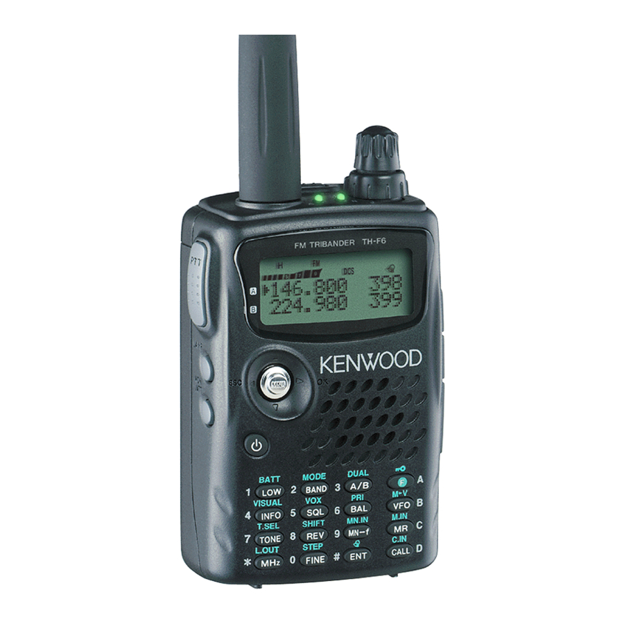
Page 9: Chapter 3 Getting Acquainted
GETTING ACQUAINTED KEYS AND CONTROLS PTT switch LAMP Key Multi-scroll MONI Key Power Switch Antenna Tuning Control VOL Control FM TRIBANDER TH-F6 Display SP/MIC jack Speaker/ Mic. DC IN jack Keypad Battery release A/ B-band status LEDs Green : Busy : Transmitting Orange: Charging... -
Page 10: Display
DISPLAY q EL Appears when the transmit output power is set to Low (“L”) or Economic Low (“EL”) {pages 7, 41}. Appears when the transmit output power is set to High (“H”) {pages 7, 41}. e LSB Appears when lower side band (LSB) is selected for B-band {page 34}. -
Page 11: Basic Operation Switching Power On/ Off
3 GETTING ACQUAINTED BASIC OPERATION SWITCHING POWER ON/ OFF 1 Press [ ] (POWER) briefly to switch the transceiver power ON. • Upon power up, a high pitched double beep sounds, followed by the frequencies and other indicators. 2 To switch the transceiver OFF, press [ (POWER) again. -
Page 12: Transmitting
TRANSMITTING 1 To transmit, hold the transceiver approximately 5 cm (2 inches) from your mouth, then press and hold the PTT switch and speak into the microphone in your normal tone of voice. • The status LED on the top panel lights red and bar-graph meter appears. - Page 13 3 GETTING ACQUAINTED Example 1 (100 MHz < f < 1000 MHz) To enter 438.320 MHz: Key in Display [ENT] – – – – – – [4], [3], [8] 4 3 8. – – – [3], [2], [0] 4 3 8. 3 2 0 Note: You do not have to press [MHz] when you are entering 3-digit MHz number.
-
Page 14: Chapter 4 Menu Setup
MENU SETUP WHAT IS A MENU? Many functions on this transceiver are selected or configured via a software-controlled Menu, rather than through the physical controls of the transceiver. Once familiar with the Menu system, you will appreciate the versatility it offers. You can customize the various timings, settings, and programming functions on this transceiver to meet your needs without using many controls and switches. - Page 15 4 MENU SETUP i n i o l l t f i i t c e l i t t i c i t v i t y t i s i t v i t —...
-
Page 16: Alphabetical Function List
ALPHABETICAL FUNCTION LIST — — 4 MENU SETUP —... -
Page 17: Chapter 5 Operating Through Repeaters
The default offset frequency on the 2 m band is 600 kHz (all models); the default on the 70 cm band is 5.0 MHz (TH-F6A) or 1.6 MHz (TH-F7E); the default on the 1.25 m band is 1.6 MHz (TH-F6A). -
Page 18: Activating Tone Function
This function automatically selects an offset direction, according to the frequency that you select on the 2 m and 1.25 m (TH-F6A only) bands. The transceiver is programmed for offset direction as shown below. To obtain an up-to-date band plan for repeater offset direction, contact your national Amateur Radio association. -
Page 19: Reverse Function
5 OPERATING THROUGH REPEATERS REVERSE FUNCTION The reverse function exchanges a separate receive and transmit frequency. So, while using a repeater, you can manually check the strength of a signal that you receive directly from the other station. If the station’s signal is strong, both stations should move to a simplex frequency and free up the repeater. -
Page 20: Chapter 6 Memory Channels
MEMORY CHANNELS In memory channels, you can store frequencies and related data that you often use. Then you need not reprogram those data every time. You can quickly recall a programmed channel through simple operation. A total of 400 memory channels are available for storing the frequencies, modes and other operating conditions of the A and B-bands. -
Page 21: Recalling A Memory Channel
6 MEMORY CHANNELS RECALLING A MEMORY CHANNEL There are 2 ways of recalling the desired memory channel. Using the Tuning Control or / 1 Press [MR] to enter Memory Recall mode. • The memory channel used last is recalled. 2 Turn the Tuning control or press [ ]/ [ ] to select your desired memory channel. -
Page 22: Naming A Memory Channel
NAMING A MEMORY CHANNEL You can name memory channels using up to 8 alphanumeric characters. When you recall a named memory channel, its name appears on the display in place of the stored frequency. Names can be call signs, repeater names, cities, names of people, etc. 1 Press [MR] to recall your desired memory channel. -
Page 23: Memory Channel Groups
6 MEMORY CHANNELS MEMORY CHANNEL GROUPS 400 memory channels have been divided into 8 groups of 50. Group 0 contains memory channel numbers 0 ~ 49, group 1 is 50 ~ 99, group 2 is 100 ~ 149, and so on. You can categorize each group to store similar data, same frequency bands or same modes for ease of use. -
Page 24: Call Channel
The default Call channel frequencies are 144.000 MHz for the 2 m band, 223.000 MHz for 1.25 m band (TH-F6A), 430.000 MHz (TH-F7E)/ 440.000 MHz (TH-F6A) for the 70 cm band. Each Call channel can be reprogrammed either as a simplex or odd-split channel. -
Page 25: Information Channels
6 MEMORY CHANNELS INFORMATION CHANNELS 10 Information channels are available for storing radio broadcasting service frequencies, such as weather radio stations and community FM broadcasting stations. For your conveniences, pressing [INFO] instantly recalls the Information channel to B-band. The following frequency data is stored by default. -
Page 26: Channel Display
CHANNEL DISPLAY While in this mode, the transceiver displays only memory channel numbers (or memory names if stored) instead of frequencies. 1 Press [A/B]+[ ] (POWER). • The transceiver displays the memory channel number in place of the operating frequencies. 2 Turn the Tuning control or press [ ]/ [ ] to select your desired memory channel number. -
Page 27: Chapter 7 Scan
SCAN Scan is a useful function for hands-off monitoring of your favorite frequencies. By becoming comfortable with all types of Scan, you will increase your operating efficiency. This transceiver provides the following types of scans. l l a - l l l l a y t i f i c... -
Page 28: Program Scan
PROGRAM SCAN You can limit the scanning frequency range. There are 10 memory channel pairs (L0/U0 ~ L9/U9) available for specifying the start and end frequencies. It monitors the range between the start and end frequencies that you have stored in memory channels L0/U0 to L9/U9. -
Page 29: Memory Scan
7 SCAN MEMORY SCAN Memory Scan monitors all memory channels in which you have stored frequencies (All-Channel Scan) or only a desired group of memory channels (Group Scan). ALL-CHANNEL SCAN The transceiver scans all of the memory channels in which you have stored frequencies. 1 Press [MR] (1 s). -
Page 30: Call Scan
CALL SCAN A Call channel can be stored for each amateur radio band, such as the 2 m, 70 cm, and 1.25 m (TH-F6A only) bands {page 19}. You can monitor one of these Call channels and the current operating frequency alternatively. -
Page 31: Information Channel Scan
7 SCAN Note: The signal being received on the B-band may become intermittent because the Priority Scan uses the B-band receiver to check the priority channel(s) activities. When a signal is received on a Priority channel with a CTCSS or DCS code programmed, the Priority channel is recalled even if a different selective tone/ code is detected. -
Page 32: Using Visual Scan (Memory Channel)
USING VISUAL SCAN (MEMORY CHANNEL) 1 Press [MR] to enter Memory Recall mode. 2 Turn the Tuning control or press [ ]/ [ ] to select your desired center memory channel. 3 Press [F], [INFO] to start the Visual Scan. •... -
Page 33: Chapter 8 Selective Call
SELECTIVE CALL CTCSS and DCS You may sometimes want to hear calls from only specific persons or groups. In this case, use the selective call function. This transceiver is equipped with CTCSS (Continuous Tone Coded Squelch System) and DCS (Digital Coded Squelch). These selective calls allow you to ignore (not hear) unwanted calls from other persons who are using the same frequency. -
Page 34: Ctcss Freq. Id Scan
CTCSS FREQ. ID SCAN This function scans through all CTCSS frequencies to identify the incoming CTCSS frequency on the received signal. You may find this useful when you cannot recall the CTCSS frequency that the other persons in your group are using. 1 While the CTCSS function is ON, press [F], [TONE] (1 s) to start the CTCSS Freq. -
Page 35: Dcs Code Id Scan
8 SELECTIVE CALL DCS CODE ID SCAN This function scans through all DCS codes to identify the incoming DCS code on the received signal. You may find this useful when you cannot recall the DCS code that the other persons in your group are using. 1 While in DCS mode, press [F], [TONE] (1 s) to start the DCS Code ID Scan function. -
Page 36: Chapter 9 Dtmf Functions
DTMF FUNCTIONS The keys on the keypad also function as DTMF keys; the 12 keys found on a touch-tone phone plus 4 additional keys (A, B, C, D). This transceiver also provides 10 dedicated DTMF memory channels. You can store a DTMF number (16 digits max.) with a memory name (8 digits max.) in each of the channels to recall later for speed dialing. -
Page 37: Transmitting A Stored Dtmf Number
9 DTMF FUNCTIONS • Pressing [ ] after selecting the 8th digit completes the programming. • To complete programming a name with less than 8 digits, press [MNU] or [ ] twice. • Each press of [ ] causes the cursor to move backward. -
Page 38: Chapter 10 Utilizing The B-Band
The frequency for the B-band appears on the bottom part of the display. Although the A-band transceiver covers only the 2 m/ 1.25 m (TH-F6A only)/ 70 cm amateur radio bands in FM mode, the B-band receiver can receive signals from 100 kHz to 470 MHz in SSB, CW, FM, or AM mode, and from 470 MHz to 1.3 GHz in FM or AM mode. -
Page 39: B-Band Frequency Coverage (Th-F7E)
10 UTILIZING THE B-BAND B-band Frequency Coverage (TH-F7E) Note: By default, the Fine Tuning function is activated automatically for 1.71 MHz ~ 29.7 MHz. SELECTING A MODE FOR THE B-BAND When using the B-band receiver, the following receiving mode is available. LSB/ USB/ CW/ AM/ FM/ WFM To select the receiving mode for the B-band: 1 Press [VFO]. -
Page 40: Fine Tuning
FINE TUNING When you operate the B-band in LSB, USB, CW, or AM mode, you can turn the Fine Tuning function ON. You can further configure the Fine Tuning frequency step size from 33 Hz, 100 Hz (default), 500 Hz, or 1000 Hz. -
Page 41: Chapter 11 Operator Conveniences
OPERATOR CONVENIENCES APO (Auto Power OFF) The transceiver switches OFF automatically if no keys or controls are pressed or adjusted, and no signal is received for 30 minutes (default). 1 minute before the transceiver switches OFF, warning beeps sound for a few seconds and “APO” blinks. Then, the transceiver turns OFF automatically. -
Page 42: Battery Saver
Note: Use the PB-42L (Lithium battery pack) within the temperature range of –10 C ~ 50 C (14 F ~ 122 F). BATTERY SAVER Battery Saver extends the operating time of the transceiver. It automatically activates when the squelch is closed and no key is pressed for more than 10 seconds. -
Page 43: Lamp
(or key combination) functions. The default assignments are as follows. Mic [1]: A/B Mic [2]: VFO/ MR Mic [3]: CALL (TH-F6A)/ 1750 Hz (TH-F7E) Note: Turn the transceiver OFF before connecting the optional speaker microphone. If the LOCK switch on the rear of the microphone is ON, you must move the switch to the OFF position to program the keys. -
Page 44: Monitor
You can also operate the transceiver in narrow band FM deviation ( 2.5 kHz) mode on 2 m, 1.25 m (TH-F6A only), and 70 cm bands for both A and B-bands. To operate the transceiver in narrow band FM: 1 Press [MNU]. -
Page 45: Single Band Operation
11 OPERATOR CONVENIENCES • The current programmable frequency range for the band appears. 6 Press [ ] or [MNU]. 7 Turn the Tuning control or press [ ]/ [ ] to select the lower limit frequency in MHz. 8 Press [ ] or [MNU] to store the lower limit frequency. -
Page 46: Tx Power
TX POWER To change the transmission output power: Press [LOW]. • Each time you press [LOW], the icon cycles from EL, and then goes back to H. The output power varies depending on the battery type and operating voltage. The table below shows the approximate output power when the transceiver operates with different types of battery or DC power source. -
Page 47: Vox On Busy
11 OPERATOR CONVENIENCES From the Menu: 1 Press [MNU]. 2 Turn the Tuning control or press [ ]/ [ ] to select Menu No. 21 (VOX GAIN). 3 Press [ ] or [MNU]. 4 Turn the Tuning control or press [ ]/ [ ] to select the desired VOX Gain (default is 4). -
Page 48: Chapter 12 Wireless Remote Control
WIRELESS REMOTE CONTROL (TH-F6A ONLY) If you also have a KENWOOD multi-band mobile transceiver, you can control one of its bands by sending DTMF tones from this portable transceiver. You will find this function useful when you want to control your mobile transceiver from a location outside your vehicle. -
Page 49: Optional Accessories
OPTIONAL ACCESSORIES BT-13 EMC-3 Battery Case (4 AA/ LR6) Clip Microphone with Earphone PB-42L PG-2W Li-ion Battery Pack DC Power Cable (7.4 V, 1550 mAh) SMC-33 SMC-34 Speaker Microphone (with Speaker Microphone (with PF keys) PF keys and VOL control) HMC-3 KHS-21 Headset (with VOX/ PTT) -
Page 50: Chapter 14 Interfacing To Peripherals
{page 38}. TH-F6A/ TH-F7E Note 1: Voltage is developed across a 100 resistor on the 3.5 V line in the transceiver. When 2 mA flows, approximately 3.3 V is developed. - Page 51 PC, access Menu No. 9 and select “PC”. PC with a serial (COM) port PC Interface cable TH-F6A/ TH-F7E For your information, the following diagram shows how the TH-F6A/ TH-F7E communicates to the PC using a serial (COM) port. TH-F6A/ TH-F7E 2.5 mm Plug 3.5 mm...
-
Page 52: Chapter 15 Troubleshooting
You may return your transceiver for service to the authorized KENWOOD dealer from whom you purchased it or any authorized KENWOOD service center. A copy of the service report will be returned with the transceiver. Please do not send subassemblies or printed circuit boards. -
Page 53: Troubleshooting
15 TROUBLESHOOTING TROUBLESHOOTING The problems described in the following table are commonly encountered operational malfunctions. These types of difficulties are usually caused by improper hook-up, accidental incorrect control settings, or operator error due to incomplete programming. These problems are usually not caused by circuit failure. Please review this table, and the appropriate section(s) of this instruction manual, before assuming your transceiver is defective. - Page 54 s t i c t i c t i “ ” n i l t f i . t r c i t s ’ s t i S “ f ” 15 TROUBLESHOOTING i t c i t c t f i t f i “...
-
Page 55: Microprocessor Reset
• A-band: 144.000 MHz/ FM • B-band: 440.000 MHz/ FM (TH-F6A) B-band: 430.000 MHz/ FM (TH-F7E) The Memory channels have no data stored. Refer to pages 19 and 20 for the Call Channels and Information Channels default values. -
Page 56: Operation Notices
15 TROUBLESHOOTING BEAT AND NOISE When you have the same 2 m, 1.25 m (TH-F6A only), and 70 cm band frequencies for both A and B-band receivers, the Visual Scan may indicate the signals on the bar-graph display even if no signal is monitored on the A-band receiver. -
Page 57: Internal Beats Frequency Formula
(A-band receive freq. – 59.85 MHz) x 9 – (70 cm band receive freq. on the B-band – 57.6 MHz) x 9 = 59.85 MHz or 57.6 MHz (A-band receive freq. – 59.85 MHz) x 10 – (70 cm band receive freq. on the B-band – 57.6 MHz) x 10 = 59.85 MHz or 57.6 MHz TH-F6A only Excluding the TH-F6A... -
Page 58: Specifications
SPECIFICATIONS l i b y t i t t i Specifications are guranteed within 438 ~ 450 MHz. v i t – – ( – – ( – ( – l a i " 3 " 4 " 2 " 3 "... - Page 59 16 SPECIFICATIONS v i t y t i v i t y t i v i t y t i – – < <...
-
Page 60: Tv Channels (Vhf)
APPENDIX TV CHANNELS (VHF) i r f i l i — — i r t... -
Page 61: Tv Channels (Uhf)
17 APPENDIX TV CHANNELS (UHF) i r f... -
Page 62: Marine Channels (Vhf)
MARINE CHANNELS (VHF) * Pacific coast only CITIZEN BAND CHANNELS 17 APPENDIX... -
Page 63: Index
INDEX A-band ... 6 All-channel Scan ... 24 Alkaline Batteries, Installing ... 1 APO (Auto Power OFF) ... 36 AM ... 34 AM Band ... 33, 34 ASC ... 14 Attenuator ... 36 Automatic Dialer... 31 Automatic Repeater Offset ... 13 Automatic Simplex Check ...