Kenwood TH-D7A Instruction Manual
Fm dual bander
Hide thumbs
Also See for TH-D7A:
- Instruction manual (30 pages) ,
- Sercie manual (61 pages) ,
- Operation manual (8 pages)
Table of Contents
Advertisement
Quick Links
Download this manual
See also:
Operating Manual
Advertisement
Table of Contents

Related Manuals for Kenwood TH-D7A


Summary of Contents for Kenwood TH-D7A
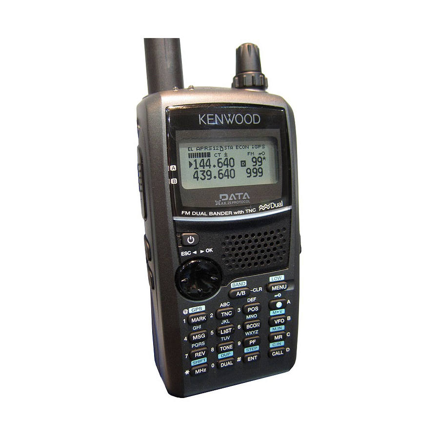
- Page 1 INSTRUCTION MANUAL 144/440 MHz FM DUAL BANDER TH-D7A 144/430 MHz FM DUAL BANDER TH-D7E STA CON PACKET96BCONDUP KENWOOD CORPORATION B62-1004-00 (K,E) (A) 09 08 07 06 05 04 03 02 01 00...
- Page 2 • Enhances the functions of an optional VC-H1 Interactive Visual Communicator designed for plug-and-play color slow-scan television (SSTV). • Utilizes Sky Command System 2 designed to control a KENWOOD HF transceiver at a remote location (TH-D7A only).
- Page 3 Nickel-Cadmium batteries must be replaced or disposed of properly. State laws may vary regarding the handling and disposal of Nickel-Cadmium batteries. Please contact your authorized KENWOOD dealer for more information. One or more of the following statements may be applicable: FCC WARNING This equipment generates or uses radio frequency energy.
-
Page 4: Table Of Contents
RECALLING A MEMORY CHANNEL ... 28 CLEARING A MEMORY CHANNEL ... 28 NAMING A MEMORY CHANNEL ... 29 CALL CHANNEL (TH-D7A ONLY) ... 30 Recalling the Call Channel ... 30 Reprogramming the Call Channel ... 30 MEMORY-TO-VFO TRANSFER ... 31 CHANNEL DISPLAY ... - Page 5 AUTOMATIC POWER OFF (APO) ... 49 BATTERY SAVER ... 49 POWER-ON MESSAGE ... 50 TRANSCEIVER LOCK ... 50 TX INHIBIT ... 51 SWITCHING AM/FM MODE (TH-D7A ONLY) ... 51 ADVANCED INTERCEPT POINT (AIP) ... 51 SWITCHING TX DEVIATION (TH-D7E ONLY) ... 51 CHAPTER PACKET OPERATION CONNECTING WITH A PERSONAL COMPUTER ..
- Page 6 WIRELESS REMOTE CONTROL (TH-D7A ONLY) PREPARATION ... 81 CONTROL OPERATION ... 82 CHAPTER SKY COMMAND 2 2 2 2 2 (TH-D7A ONLY) CONNECTING THE TRANSPORTER WITH THE HF TRANSCEIVER ... 84 PREPARATION FLOW ... 85 PROGRAMMING CALL SIGNS ... 86 PROGRAMMING A TONE FREQUENCY ...
-
Page 7: Supplied Accessories
SUPPLIED ACCESSORIES ) " PB-39 (9.6 V, 600 mAh) PB-38 (6 V, 650 mAh) Use this accessory to modify the cable end of your GPS receiver {page 61}. CONVENTIONS FOLLOWED IN THIS MANUAL The writing conventions described below have been y t i followed to simplify instructions and avoid unnecessary repetition. -
Page 8: Preparation
INSTALLING THE NiCd BATTERY PACK 1 Position the two grooves on the inside bottom corners of the battery pack over the corresponding guides on the back of the transceiver. Guide 2 Slide the battery pack along the back of the transceiver until the release latch on the base of the transceiver locks the battery pack in place. -
Page 9: Installing The Antenna
The following table shows the approximate battery life (hours) relative to the transmit output power. Note: Charge the NiCd battery pack within an ambient temperature of between 5 C and 40 C (41 F and 104 F). Charging outside this range may not fully charge the pack. -
Page 10: Installing Alkaline Batteries
INSTALLING ALKALINE BATTERIES With an optional BT-11 battery case, you can use commercially available alkaline batteries in such occasions as camping or emergency operations. 1 To open the battery case cover, push on the locking tab, then pull the cover. Locking tab 2 Insert four AA (LR6) alkaline batteries. -
Page 11: Connecting With A Regulated Power Supply
DC IN jack Note: Only use the power supplies recommended by your authorized KENWOOD dealer. The supply voltage must be between 5.5 V and 16 V to prevent damaging the transceiver. If input voltage exceeds approximately 18 V, warning beeps sound and a warning message appears. -
Page 12: Chapter 2 First Qso
The 7 steps given here will get you on the air in your first QSO right away. So, you can enjoy the exhilaration that comes with opening a brand new transceiver. Press the POWER switch for 1 second or longer. Turn the VOL control clockwise to the 11 o’clock position. -
Page 13: Switching Power On/Off
SWITCHING POWER ON/OFF 1 Press the POWER switch (1 s) to switch ON the transceiver. • A double beep sounds. 2 To switch OFF the transceiver, press the POWER switch (1 s) again. ADJUSTING VOLUME Turn the VOL control clockwise to increase the audio level and counterclockwise to decrease the audio level. -
Page 14: Adjusting Squelch
ADJUSTING SQUELCH Selecting the correct squelch level relieves you from listening to background noise output from the speaker when no signals are present. The appropriate squelch level depends on ambient noise conditions. You can program a different level for band A and B. (Squelch opened) The current squelch level is incorrect. -
Page 15: Transmitting
Also, transmitting near a poorly regulated power supply, that is not recommended by KENWOOD, may cause the power supply to output an extremely high voltage. This voltage could damage both your transceiver and any other equipment connected to the power supply. -
Page 16: Chapter 4 Getting Acquainted
ORIENTATION PTT switch POWER switch LAMP key MONI key Cursor keys GETTING ACQUAINTED Antenna Tuning control VOL control SP jack Display MIC jack PC jack GPS jack Speaker/ Microphone Keypad DC IN jack TX/RX indicator... -
Page 17: Indicators
INDICATORS On the upper section of the display you will see various indicators that show what you have selected. TH-D7E only Shows the strength of received signals. While transmitting, shows the current relative battery charge. Note: Electromagnetic fields, such as those produced by static electricity, may occasionally cause the display to function abnormally. -
Page 18: Cursor Keys
A and band B. The band A default is VHF (144 MHz) and the band B default is UHF. In band A you can also recall a 118 MHz sub-band (TH-D7A only). In band B you can also recall a VHF (144 MHz) sub-band. -
Page 19: Basic Transceiver Modes
BASIC TRANSCEIVER MODES This section introduces you to the basic modes you can select on this transceiver. VFO mode Press [VFO] to select. In this mode you can change the operating frequency by pressing [UP]/ [DWN] or entering digits directly from the keypad {page 45}. Memory Recall mode Press [MR] to select. - Page 20 Full Duplex mode Press [DUP] to select. In this mode the transceiver is capable of simultaneously transmitting and receiving signals. So, it is possible to transmit audio on the current band while receiving packet data on another band. For further information, refer to “FULL DUPLEX” {page 55}.
-
Page 21: Keypad Direct Entry
KEYPAD DIRECT ENTRY The keypad allows you to make various entries depending on which mode the transceiver is in. In VFO or Memory Recall mode, use the keypad to select a frequency {page 45} or memory channel number {page 28}. Press [ENT] first. In Menu mode, use the keypad to select a menu item. -
Page 22: Chapter 5 Menu Set-Up
The Menu system on this transceiver consists of 3 levels. Level 1 Level 2 Level 3 1 2 1 2 1 2 3 4 1 2 1 2 3 4 5 6 7 Menu 1–3–1 MENU ACCESS 1 Press [MENU] to enter Menu mode. •... -
Page 23: Menu Configuration
MENU CONFIGURATION c i t c i t —... - Page 24 t i s t c i l a i / l l — l a i / l l — — — — — — — — e l i o l i e l i...
- Page 25 t i s o l l o l l o l l — — — — — — — —...
-
Page 26: Chapter 6 Operating Through Repeaters
Repeaters, which are often installed and maintained by radio clubs, are usually located on mountain tops or other elevated locations. Generally they operate at higher ERP (Effective Radiated Power) than a typical station. This combination of elevation and high ERP allows communications over much greater distances than communications without using repeaters. -
Page 27: Programming Offset
The default offset frequency on the VHF band is 600 kHz no matter which market version; the default on the UHF band is 5 MHz (TH-D7A) or 1.6 MHz (TH-D7E). 1 Press [F], [5] to select “F–5 (OFFSET)”. PACKET96BCONDUP 2 Press [UP]/ [DWN] to select the appropriate offset frequency. -
Page 28: Activating Tone Function
Activating Tone Function Press [F], [1] to switch the Tone function ON (or OFF). • “ ” appears when the Tone function is ON. Note: You cannot use the Tone and CTCSS functions simultaneously. Switching the Tone function ON after activating the CTCSS deactivates the CTCSS. -
Page 29: Automatic Repeater Offset
AUTOMATIC REPEATER OFFSET This function automatically selects an offset direction, according to the frequency that you select on the VHF band. The transceiver is programmed for offset direction as shown below. To obtain an up-to-date band plan for repeater offset direction, contact your national Amateur Radio association. -
Page 30: Reverse Function
REVERSE FUNCTION The reverse function exchanges a separate receive and transmit frequency. So, while using a repeater, you can manually check the strength of a signal that you receive directly from the other station. If the station’s signal is strong, both stations should move to a simplex frequency and free up the repeater. -
Page 31: Tone Freq. Id
TONE FREQ. ID This function scans through all tone frequencies to identify the incoming tone frequency on a received signal. You may use the function to find which tone frequency is required by your local repeater. 1 Press [F], [2] (1 s) to activate the function. •... -
Page 32: Chapter 7 Memory Channels
In memory channels, you can store frequencies and related data that you often use. Then you need not reprogram those data every time. You can quickly recall a programmed channel by simple operation. A total of 200 memory channels are available for bands A and B. SIMPLEX &... -
Page 33: Storing Simplex Frequencies Or Standard Repeater Frequencies
STORING SIMPLEX FREQUENCIES OR STANDARD REPEATER FREQUENCIES 1 Select the desired band. 2 Press [VFO]. 3 Press [UP]/ [DWN] to select the desired frequency. • You can also directly enter digits from the keypad. See page 45. 4 If storing a standard repeater frequency, select the following data: •... -
Page 34: Recalling A Memory Channel
RECALLING A MEMORY CHANNEL 1 Select the desired band. 2 Press [MR] to enter Memory Recall mode. • The memory channel used last is recalled. 3 Press [UP]/ [DWN] to select the desired memory channel. • You cannot recall an empty memory channel. •... -
Page 35: Naming A Memory Channel
NAMING A MEMORY CHANNEL You can name memory channels using up to 8 alphanumeric characters. When you recall a named memory channel, its name appears on the display instead of the stored frequency. Names can be call signs, repeater names, cities, names of people, etc. 1 Recall the desired memory channel. -
Page 36: Call Channel (Th-D7A Only)
CALL CHANNEL (TH-D7A ONLY) The Call channel can always be selected quickly no matter what mode the transceiver is in. For instance, you may use the Call channel as an emergency channel within your group. In this case, the Call/VFO scan {page 38} will be useful. -
Page 37: Memory-To-Vfo Transfer
MEMORY-TO-VFO TRANSFER You may sometimes want to search for other stations or a clear frequency, near the frequency stored in a memory channel or the Call channel. In this case first transfer the contents of a memory channel or the Call channel to the VFO. -
Page 38: Partial Or Full Reset
Partial Reset nor Full Reset. VHF Band Defaults UHF Band Defaults 1 Press [F]+ POWER ON. • “RESET?” appears. • You can also use Menu 1–5–7 (TH-D7A) or Menu 1–5–9 – – 2 Press [UP]/ [DWN] to select Partial (VFO) Reset or Full Reset. - Page 39 CTCSS tone that you selected. Starting Scan switches OFF the Automatic Simplex Check. SCAN This transceiver provides the following types of scans: l l a / l l TH-D7A only Stop f l l f l l f l l...
-
Page 40: Selecting Scan Resume Method
SELECTING SCAN RESUME METHOD The transceiver stops scanning at a frequency (or memory channel) on which a signal is detected. It then continues scanning according to which resume mode you select. You can choose one of the following modes. The default is Time-operated mode. •... -
Page 41: Vfo Scan
VFO SCAN VFO Scan monitors all frequencies tunable on the band, using the current frequency step size. 1 Select the desired band. 2 Press [VFO] (1 s). • Scan starts at the frequency currently displayed. • The 1 MHz decimal blinks while scanning is in progress. •... -
Page 42: Locking Out A Memory Channel
Locking Out a Memory Channel Select memory channels that you prefer not to monitor while scanning. 1 Recall the desired memory channel. 2 Press [F], [0] to switch Lockout ON (or OFF). • A star appears above the channel number when the channel is locked out. -
Page 43: Program Scan
PROGRAM SCAN Program Scan is identical with VFO Scan except that you select the frequency range of the scan. Setting Scan Limits You can store up to 10 scan ranges in memory channels L0/U0 to L9/U9. 1 Select the desired band. 2 Press [VFO]. -
Page 44: Using Program Scan
If the current VFO frequency is within more than one programmed scan range, the range stored in the smallest channel number is used. CALL/VFO SCAN (TH-D7A ONLY) Use Call/VFO Scan to monitor both the Call channel and the current VFO frequency on the selected band. -
Page 45: Selecting A Ctcss Frequency
CONTINUOUS TONE CODED SQUELCH SYSTEM (CTCSS) You may sometimes want to hear calls from only specific persons. The Continuous Tone Coded Squelch System (CTCSS) allows you to ignore (not hear) unwanted calls from other persons who are using the same frequency. First select the same CTCSS tone as selected by the other persons in your group. -
Page 46: Using Ctcss
USING CTCSS 1 Press [A/B] to select band A or B. • If necessary, press [F], [A/B] to recall the sub-band. 2 Press [F], [3] to switch the CTCSS function ON (or OFF). • “CT” appears when CTCSS is ON. You will hear calls only when the selected tone is received. -
Page 47: Manual Dialing
DUAL TONE MULTI-FREQUENCY (DTMF) FUNCTIONS The keys on the keypad also function as DTMF keys; the 12 keys found on a push-button telephone plus 4 additional keys (A, B, C, D). This transceiver provides 10 dedicated memory channels. You can store a DTMF number (16 digits max.) with a memory name (8 digits max.) in each of the channels to recall later for a quick call. -
Page 48: Automatic Dialer
AUTOMATIC DIALER If you use the 10 dedicated memory channels to store DTMF numbers, you need not remember a long string of digits. Storing a DTMF Number in Memory Note: Audible DTMF tones from other transceivers near you (or from your own speaker) may be picked up by your microphone. -
Page 49: Transmitting A Stored Dtmf Number
Transmitting a Stored DTMF Number 1 Press [PTT]+[MENU]. STA CON PACKET96BCONDUP 2 Release only [MENU], then press [UP]/ [DWN] to select the desired DTMF memory channel. 3 While still holding [PTT], press [MENU] again. • The number stored in the channel scrolls across the display accompanied by DTMF tones from the speaker. -
Page 50: Chapter 11 Microphone Control
MICROPHONE CONTROL The key functions you can assign are shown below: Press [F] first. Press [F] first. TH-D7A only Note: Turn OFF the transceiver power before connecting the optional speaker microphone. If the LOCK on the speaker microphone is ON, you cannot reprogram the Programmable Function keys. -
Page 51: Direct Frequency Entry
DIRECT FREQUENCY ENTRY If the desired operating frequency is far from the current frequency, using the keypad is the quickest way to change frequency. 1 Press [A/B] to select band A or B. • If necessary, press [F], [A/B] to recall the sub-band. 2 Press [VFO]. -
Page 52: Changing Frequency Step Size
Tuning control or [UP]/ [DWN]. The default step size on the VHF band is 5 kHz (TH-D7A) or 12.5 kHz (TH-D7E). The default on the UHF band is 25 kHz no matter which market version. -
Page 53: Tone Alert
TONE ALERT Tone Alert provides an audible alarm when signals are received on the frequency you are monitoring. In addition, it shows the number of hours and minutes elapsed after signals were received. If you use Tone Alert with CTCSS, it alarms only when a received CTCSS tone matches the tone you selected. -
Page 54: Adjusting Volume Balance
ADJUSTING VOLUME BALANCE While simultaneously receiving on 2 bands, you may sometimes feel that audio output on either band is too noisy. You can adjust the volume on the noisy band. 1 Press [BAL]. • The balance scale appears with a blinking cursor. 2 Press [UP]/ [DWN] to change the setting. -
Page 55: Automatic Power Off (Apo)
AUTOMATIC POWER OFF (APO) Automatic Power Off is a background function that monitors whether any keys have been pressed, or whether any control has been turned. After the predetermined time passes with no operations, APO turns OFF the power. However, 1 minute before the power turns OFF, “APO”... -
Page 56: Power-On Message
POWER-ON MESSAGE Each time you switch the transceiver ON, “HELLO !!” appears and stays for approximately 1 second. You can program your favorite message in place of the factory default. 1 Press [MENU] to enter Menu mode. 2 Press [1], [1], [1] to select “1–1–1 (PWR ON MSG)”. •... -
Page 57: Tx Inhibit
You may use this function when operating on the VHF band. Access Menu 1–5–6 (TH-D7A) or Menu 1–5–8 (TH-D7E) and select “ON”. Note: This transceiver does not allow you to use the AIP on the UHF band. -
Page 58: Chapter 13 Packet Operation
Packet is a unit of data transmitted as a whole from one computer to another on a network. Packets can be transmitted on radio waves as well as on communications lines. Besides a transceiver and a computer, all you need is a terminal node controller (TNC). -
Page 59: Connecting With A Personal Computer
CONNECTING WITH A PERSONAL COMPUTER You can use an optional PG-4W cable to connect the transceiver with a personal computer. For this cable, contact your authorized KENWOOD dealer. Note: Turn OFF the transceiver power before making the connection. To PC jack... -
Page 60: Preparation Flow
PREPARATION FLOW The following steps should guide you to a good start of packet operation. The shaded steps indicate operations on your personal computer. First connect the transceiver to the personal computer {page 53}. Note: You may switch Battery Saver OFF {page 49} to prevent the initial portion of a received packet from being missed. -
Page 61: Selecting Data Band
SELECTING DATA BAND This transceiver is capable of receiving packet data on one band (data band) while receiving audio on another band. Select band A or B as the data band for receiving or transmitting packets. “ ” indicates the current data band;... -
Page 62: Chapter 14 Dx Packetclusters Monitor
DX PacketClusters are networks which consist of nodes and stations who are interested in DXing and contesting. If one station finds a DX station on the air, he (or she) sends a notice to his (or her) node. Then this node passes the information to all its local stations besides another node. -
Page 63: Chapter 15 Slow-Scan Television (Sstv) With Vc-H1
VC-H1 monitor. You can also select colors for those information. Note: Use an optional PG-4V cable to connect the VC-H1 to this transceiver. For this cable, contact your authorized KENWOOD dealer. The cable that comes with the VC-H1 allows only image transfer from/ to other stations. -
Page 64: Entering Call Sign/ Message/ Rsv
ENTERING CALL SIGN/ MESSAGE/ RSV Use the following procedures to enter a call sign, a message, or an RSV report. RSV stands for readability, signal strength, and video. If you receive a clear image free from noise, the RSV report should be 595. Note: The only difference among Menus 3–1, 3–3, and 3–5 is the maximum number of digits that you can enter. -
Page 65: Selecting Color For Call Sign/ Message/ Rsv
SELECTING COLOR FOR CALL SIGN/ MESSAGE/ RSV You can select white (default), black, blue, red, magenta, green, cyan, or yellow to color the call sign, message, or RSV report. 1 Press [MENU] to enter Menu mode. 2 Press [3], [2] to select “3–2 (MY CALL COL)”, or [3], [4] to select “3–4 (MESSAGE COL)”, or [3], [6] to select “3–6 (RSV COLOR)”. -
Page 66: Vc-H1 Control
VC-H1 CONTROL If you have another transceiver that has the Tone function, you can use it as a remote control for the VC-H1. Transmit a subaudible tone from the remote control to this transceiver connected with the VC-H1 for more than 1 second. Then this transceiver causes the VC-H1 to capture an image, executes the superimposition, and transmits the image to the target station. - Page 67 AUTOMATIC PACKET/ POSITION REPORTING SYSTEM The Automatic Packet/ Position Reporting System (APRS ) is a software program and registered trademark of Bob Bruninga, WB4APR. He has made packet communications much more exciting than before. This program allows you to track mobile stations on a map which you recall on a computer screen.
-
Page 68: Operation Flow
OPERATION FLOW The following steps should guide you to a good start of APRS operation. q Press [TNC] to switch ON the TNC. • “ ” appears. w Access Menu 1–4–1 to select band A or B as the data band {page 55}. e On the data band select the same frequency as other stations in your group. -
Page 69: Receiving Aprs Data
RECEIVING APRS DATA Each time new APRS data is received, the frequency display is interrupted to show information as below: STA CON 96BCONDUP • The received APRS data may include information on an object such as a hurricane or tornado. In this case, the name of the object appears instead of a call sign. -
Page 70: Accessing Received Aprs Data
ACCESSING RECEIVED APRS DATA This transceiver is capable of receiving and storing APRS data from up to 40 stations in memory. You can select the desired station and access the desired information, by switching the display. 1 Press [LIST]. • The display for selecting a station appears. •... - Page 71 q Position q Grid square locator q Latitude/ longitude w Distance from comment (or status text) the station (mile or km) Mobile station Fixed station q Moving direction q Transmit power q Transmit range w Moving speed w Height of antenna m: Mile/hour (elevation) k: km/hour...
-
Page 72: Programming A Call Sign
PROGRAMMING A CALL SIGN To transmit APRS data, first program your call sign using a maximum of 9 alphanumeric characters. 1 Press [MENU] to enter Menu mode. 2 Press [2], [1] to select “2–1 (MY CALL)”. • The display for entering characters appears; the first digit blinks. -
Page 73: Selecting Your Station Icon
SELECTING YOUR STATION ICON Select an icon which will be displayed on the monitors of other stations as your ID. You may select an icon depending on your current location. 1 Press [MENU] to enter Menu mode. 2 Press [2], [5] to select “2–5 (ICON)”. STA CON 3 Press [UP]/ [DWN] to select from 15 icons plus “OTHERS”. -
Page 74: Entering Latitude/ Longitude Data
ENTERING LATITUDE/ LONGITUDE DATA This transceiver allows you to manually enter latitude and longitude data to transmit to other stations. 1 Press [MENU] to enter Menu mode. • You may press [POS] instead. Then you can skip step 2. 2 Press [2], [3] to select “2–3 (My Pos)”. STA CON 96BCONDUP 3 Press [UP]/ [DWN] to switch between north latitude... -
Page 75: Selecting A Position Comment
SELECTING A POSITION COMMENT The APRS data which you transmit always include one of the 8 predetermined position comments. Select an appropriate comment depending on your situation. 1 Press [MENU] to enter Menu mode. 2 Press [2], [4] to select “2–4 (POS COMMENT)”. STA CON 3 Press [UP]/ [DWN] to select the desired comment. -
Page 76: Entering Status Text
ENTERING STATUS TEXT You can also transmit any comment (status text) with the latitude/ longitude data. If you want, enter a desired comment using a maximum of 20 alphanumeric characters. Note: Attaching a long comment can double the size and length of the packet. -
Page 77: Programming A Group Code
It does not matter whether or not the subsequent 4 digits match. The default on this transceiver is APK001; K001 stands for KENWOOD Ver.1. Note: APRS packets, which are generated via various methods, include various codes instead of group codes. Using “All calls” allows you to receive packets which include the following codes. -
Page 78: Programming A Packet Path
PROGRAMMING A PACKET PATH A packet path specifies how APRS data should be transferred via one or more repeaters. A repeater, which is used for packet transfer, is commonly called a digipeater. This came from a digital repeater. A digipeater is usually located on a mountain top or high building. - Page 79 Let us describe four basic methods for editing a packet path. Method 1 (Specific path): Program the call signs of one or more digipeaters in the sequence of transfer relay; ex. “KD6ZZV,KF6RJZ”. Method 2 (Generic path): Program “RELAY” and/or “WIDE”; ex. “RELAY,WIDE”. In this example, APRS data is transferred to any relay-type digipeater near your position first, then to any wide-type digipeater.
-
Page 80: Selecting Beacon Transmit Method
SELECTING BEACON TRANSMIT METHOD Select the operation method for transmitting APRS data. The table concludes how operations differ depending on the selection: 1 Press [MENU] to enter Menu mode. 2 Press [2], [9] to select “2–9 (DATA TX)”. 3 Press [UP]/ [DWN] to select Manual (default), PTT, or Auto. -
Page 81: Selecting Beacon Transmit Interval
SELECTING BEACON TRANSMIT INTERVAL Select an interval for automatically transmitting APRS data. The default is 5 minutes. 1 Press [MENU] to enter Menu mode. 2 Press [2], [7] to select “2–7 (TX INTERVAL)”. STA CON 3 Press [UP]/ [DWN] to select the desired interval. •... -
Page 82: Chapter 17 Aprs ® Message
The APRS supports a function for transmitting and receiving a message independent of position reports. You can transmit a message to a single station only or a bulletin to all other stations in your group. If you specify a station, the entered message is transmitted up to 5 times until a reception acknowledgment is returned. -
Page 83: Receiving A Message
RECEIVING A MESSAGE Each time a proper message is received, the frequency display is interrupted to show information as below: STA CON 96BCONDUP Indicator • The display shows only the first 24 characters of the message. • The transceiver restores the frequency display after approximately 10 seconds pass or when you press any key. -
Page 84: Accessing Received Aprs Messages
ACCESSING RECEIVED APRS MESSAGES This transceiver is capable of storing a maximum of 16 messages in memory. You can access the desired massage by switching the display. 1 Press [MSG]. 2 Press [UP]/ [DWN] to select “LIST”. 3 Press [OK]. 4 Press [UP]/ [DWN] to select the desired station. -
Page 85: Entering A Message
ENTERING A MESSAGE You can enter a message or bulletin using up to 45 alphanumeric characters. To transmit a message, first enter the call sign of the target station. To transmit a bulletin to all other stations in your group, enter “BLN ” as the call sign;... -
Page 86: Transmitting A Message
TRANSMITTING A MESSAGE When entry of a message (or bulletin) is completed, this transceiver automatically transmits it 5 times (max.) at intervals of 1 minute. For a message: The transceiver repeats transmitting up to 5 times until a reception acknowledgment is returned. 96BCONDUP STA CON For a bulletin:... -
Page 87: Chapter 18 Wireless Remote Control (Th-D7A Only) Preparation
WIRELESS REMOTE CONTROL (TH-D7A ONLY) If you also have a KENWOOD multi-band mobile transceiver, you can control one of its bands by sending DTMF tones from this handy transceiver. You will find this function useful when you want to control your mobile transceiver from a location outside your vehicle. -
Page 88: Control Operation
10 Make the transceiver enter Remote Control mode. • For the method, refer to the instruction manual for the mobile transceiver. If not described, consult your authorized KENWOOD dealer, customer service, or service center. CONTROL OPERATION When in Remote Control mode, the keys of the handy transceiver will function as below. - Page 89 TH-D7As and the optional cables which connect one TH-D7A to the HF transceiver. You will use one TH-D7A as both a remote control and speaker microphone. This TH-D7A is called “Commander”. The TH-D7 connected with the HF transceiver is called “Transporter”.
-
Page 90: Connecting The Transporter With The Hf Transceiver
CONNECTING THE TRANSPORTER WITH THE HF TRANSCEIVER You can use the optional cables (PG-4R) to connect the Transporter with the HF transceiver. For these cables, contact your authorized KENWOOD dealer. Note: Switch OFF both the Transporter and HF transceiver before making the connection. -
Page 91: Preparation Flow
PREPARATION FLOW The following steps should guide you to a good start of Sky Command operation. First connect the Transporter to the HF transceiver {page 84}. q On the Commander Select the same VHF and UHF and Transporter frequencies. w On the Commander Access Menu 4–1 to program a call sign (9 digits max.) for the Commander {page 86}. -
Page 92: Programming Call Signs
PROGRAMMING CALL SIGNS The built-in TNCs of the Commander and Transporter communicate each other when you send a control command from the Commander. So you must program different call signs (9 digits max.) on these transceivers as the IDs of the TNCs. Use the following Menu Nos. -
Page 93: Control Operation
CONTROL OPERATION When in the Sky Command mode, the keys of the Commander will function as below. Only the functions of [LAMP], [MONI], and the VOL control will not change. First switch ON the HF transceiver and press [SYNC] on the Commander. - Page 94 When [SYNC] is pressed, the Commander shows the current settings of the HF transceiver as below: q HF frequency w A (VFO A), B (VFO B), 00 ~ 99 (memory channel number) e RIT, XIT r OFF, –9.99 ~ +9.99 t “FS”...
-
Page 95: General Information
You may return this product for service to the authorized KENWOOD dealer from whom you purchased it, or any authorized KENWOOD service center. Please do not send subassemblies or printed circuit boards. Send the complete product. -
Page 96: Troubleshooting
TROUBLESHOOTING The problems described in this table are commonly encountered operational malfunctions and are usually not caused by circuit failure. Problem Nothing appears on the 1 Low supply voltage display when the transceiver is switched 2 If using the optional DC cable: ON, or the display is blinking ON and OFF. - Page 97 Problem You cannot transmit by 1 You selected a frequency outside pressing the PTT the allowable transmit frequency switch. range. 2 You selected a transmit offset that places the transmit frequency outside the allowable range. 3 TX Inhibit is ON. 4 Tone Alert is ON.
- Page 99 o l l c t i e l i Note: When two received frequencies have relationships per the equation below or other similar relationships, an internal heterodyne may be heard. This is not a defect. 2 (f – 45.05) – 4 (f + 38.85) = 38.85 or 45.05 –...
-
Page 100: Chapter 21 Optional Accessories
SMC-32 SMC-33 Speaker Remote Control Microphone Speaker Microphone EMC-3 Clip Microphone with Earphone BC-17 Wall Charger OPTIONAL ACCESSORIES SMC-34 Remote Control Speaker Microphone (with Volume Control) PB-38 PB-39 Standard Battery Pack High-power Battery Pack (6 V/ 650 mAh) (9.6 V/ 600 mAh) BC-19 SC-40 Rapid Charger... - Page 101 PG-3J VC-H1 Filtered Cigarette Interactive Visual Lighter Cable Communicator PG-4W Connection Cable to Computer (With a memory store program This software is mainly used to and a separate manual program memory channels via a (document file) personal computer. This manual gives further detailed information on specialized communications including Packet and APRS.
-
Page 102: Chapter 22 Equipment Connections
CONNECTING EQUIPMENT FOR REMOTE CONTROL Make connections as shown when remotely controlling equipment. Ø2.5 SP jack plug Ø3.5 MIC jack plug Note 1 Note 2 10 F Note 1: Voltage is developed across the 100 in the transceiver. When 2 mA flows, approximately 3.3 V is developed. -
Page 103: Specifications
– l i b y t i – With one band blanked (TNC OFF): Approx. 45 mA With one band blanked (TNC OFF): Approx. 25 mA Projections not included Antenna, belt hook, and hand strap included SPECIFICATIONS e l l e l l e l l e l l... - Page 104 v i t y t i v i t y t i v i t y t i – ( v i t y t i – ( VHF sub-band: 0.28 V or less Specifications are subject to change without notice due to advancements in technology. t t i –...
-
Page 105: Appendix
TNC COMMANDS LIST The commands supported by the built-in TNC are listed below. You must enter a space between a command name (or short-form) and a parameter, or between two parameters; ex. AU OFF, BEACON EVERY 18. — — — —... - Page 106 — — f i t — f i c “ ” y c i t f i c f i c f i c y f i l a i n i l i r r c i t l l a i f i t l i t s i l...
- Page 107 — f i c 1 l l f i c l l a l l a . . . l l a f i c f i c f i c f i c f i c 1 l l 2 l l 9 l l k i l...
- Page 108 — — f i c — f i c — f i c y l t f i c f i c r i t f i c f i c 1 l l f i c l l a l l a .
-
Page 109: Quick Reference Guide
Note: Not all functions are covered by this guide. i t c c i t QUICK REFERENCE GUIDE / l l l l a s t i i t c ) l l l l a c t i... - Page 110 First select the desired band. l l a c t i l l a s t i TH-D7A only Press [MENU] first to access the APRS Menu Nos. i t c i t c l l a s t i...
- Page 111 Call/VFO ... 38 Memory ... 35 MHz ... 36 Program ... 37 Resume Method ... 34 VFO ... 35 Sky Command 2 (TH-D7A only) ... 83 Slow-Scan Television (SSTV) ... 57 Specifications ... 97 Squelch, Adjusting ... 8 TNC ... 53 Tone Activating ...