Table of Contents
Advertisement
Quick Links
Advertisement
Table of Contents

Related Manuals for Bosch MON172CL20


Summary of Contents for Bosch MON172CL20
- Page 1 MON172CL20 Instruction Manual_en...
- Page 2 AutoDome, Bilinx, Bosch, the Bosch logo, DiBos, FastAddress and VIDOS are registered trademarks of Bosch Security Systems, inc. The following trademarks are registered with the United States Patent and Trademark Office: Pentium is a registered trademark of Intel Corporation .NET, DirectX, Internet Explorer, Microsoft, Windows, Windows 2000 and Windows XP are registered trademarks of Microsoft Corporation Due to the nature of this material, this document refers to numerous hardware and software products by their trade names, In most, if not all cases, these designations are claimed as trademarks or registered trademarks by their respective companies in the United States of America.
-
Page 3: Important Safeguards
Unauthorized substitutions may result in fire, electrical shock or other hazards. 9. Safety Check - Upon completion of servicing or repairs to the unit, ask the service technician to perform safety checks to ensure proper operating condition. Bosch Security Systems, Inc. -
Page 4: Safety Precautions
The equipment must not exceed its maximum operating temperature requirements. 2. Mechanical Loading - When rack-mounting the equip- ment, ensure that a hazardous condition is not created by uneven mechanical loading. Bosch Security Systems, Inc. - Page 5 Federal Com- munications Commission, helpful: How to Identify and Resolve Radio-TV Interference Problems. This booklet is available from the U.S. Government Printing Office, Washington, DC 20402, Stock No. 004-000-00345-4. Bosch Security Systems, Inc.
- Page 6 | MON172CL20 Preface This guide describes how to install the MON172CL20 monitor. Audience This guide is intended for qualified installation and service personnel who are familiar with the applicable national and local electrical codes. Document Conventions Convention Meaning Bold Denotes a part, item, or assembly.
- Page 7 For additional information, see www.boschsecurity.com Related Publications Refer to the latest Bosch Security Systems, Inc. Databook for the most up-to-date datasheets. To obtain a copy of the Databook, please contact your local Bosch representative. You can also visit the Bosch Security Systems World Wide Web site at: http://www.boschsecurity.com to view a cur- rent listings of our publications.
- Page 8 | MON172CL20 F01U064552 | 1.0 | 2007.02 Instruction Manual Bosch Security Systems, Inc.
-
Page 9: Table Of Contents
Table of Contents | en Table of Contents Unpacking Parts List Exploded View Description Features Power Installing the MON172CL20 Mounting the MON172CL20 4.1.1 Desktop Installation 4.1.2 Wall Mount Installation 4.1.3 Extension Cable Installation Connecting the Composite Video Signal to the Monitor... - Page 10 | Table of Contents MON172CL20 On-screen Display Menu Reference Maintenance Specifications F01U064552 | 1.0 | 2007.02 Instruction Manual Bosch Security Systems, Inc.
-
Page 11: Unpacking
Verify that all the parts listed in the Parts List below are included. If any items are missing, notify your Bosch Security Systems Sales or Customer Service Representative. The original packing carton is the safest container in which to transport the unit and must be used if returning the unit for service. -
Page 12: Exploded View
| Exploded View MON172CL20 Exploded View Fig. 2.1 Front Panel MON172CL20 Reference Button Description Input Button Selects the signal to be displayed Menu Button Selects the on-screen display (OSD) Adjusts the brightness Scrolls up in the OSD Adjusts the contrast... - Page 13 MON172CL20 Exploded View | en Fig. 2.2 Back Panel MON172CL20 Reference Button Power input connector from base or optional power supply DVI-I connector PC audio input The base unit contains the main connectors that supply power to the monitor. 100-240 VAC,...
-
Page 14: Description
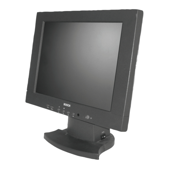
MON172CL20 Description The MON172CL20 17-inch (43-cm) Color Panel Display Monitor displays PAL or NTSC stan- dard color pictures in CCTV systems. The MON172CL20 monitor includes two (2) looping Composite Video BNC connector inputs, two (2) looping Audio RCA inputs, and two (2) loop- ing Y/C (S-Video) input using a 4-pin mini-DIN. -
Page 15: Installing The Mon172Cl20
4.1.1 Desktop Installation The MON172CL20 monitor is delivered with a 3-pole US-style power cord and a 3-pole Euro- style power cord. Use the US-style power cord where 120 VAC, 60 Hz power is available; and use the Euro-style power cord where 230 VAC, 50 Hz power is available. The monitor automat- ically adjusts to either power input voltage. - Page 16 | Installing the MON172CL20 MON172CL20 Remove the power bayonet connector from the panel (see Figure 4.2 on page 6), while sliding the base off the monitor. Fig. 4.2 Removing the Power Bayonet Mount the unit to the mounting device (not provided) using the four (4) mounting holes on the rear panel.
-
Page 17: Extension Cable Installation
4.1.3 Extension Cable Installation Use the Extension Cable (included with the MON172CL20) to place the power supply/base unit up to 1.5 m (5 ft) from the LCD panel for wall mount or rack mount installations. Follow the instructions in Section 4.1.2: Wall Mount Installation to remove the power sup- ply/base from the LCD panel section. -
Page 18: Connecting The Composite Video Signal To The Monitor
| Installing the MON172CL20 MON172CL20 Connecting the Composite Video Signal to the Monitor There are two (2) BNC connectors located on the rear of the monitor for composite video input and two (2) BNC connectors for composite video outputs (Figure 2.2 on page 3). -
Page 19: Connecting The Pc Audio To The Monitor
Connect the digital DVI-I signal by using the DVI cable (DVI-D to DVI-D) provided. Fig. 4.8 DVI-I Input and Audio Connector Identifying the DVI Cable The MON172CL20 has a DVI-I connector which supports digital (DVI) and analog (VGA) sig- nals. The unit is supplied with two (2) different DVI cables. 4.7.1 DVI-A to VGA (D-SUB) If the source has a VGA connector use the VGA cable (DVI-A to D-SUB) provided. -
Page 20: Dvi To Dvi
| Installing the MON172CL20 MON172CL20 4.7.2 DVI to DVI If the source has a DVI-I or DVI-D connector, use the DVI-D to DVI-D cable provided. Fig. 4.10 DVI-I to either DVI-D or DVI-I Reference # Description MON172CL20 DVI-I Female Connector... -
Page 21: Using A Quad Output Adapter / Dms-59 Connection
MON172CL20 Installing the MON172CL20 | en 4.7.3 Using a Quad Output Adapter / DMS-59 Connection A quad output adapter (not supplied) can be used to connect up to four LCD monitors. The best connection would require a DMS to DVI splitter cable for two (2) monitors or two (2) splitter cables to support up to four (4) monitors. -
Page 22: Ventilation
| Installing the MON172CL20 MON172CL20 Ventilation To prevent overheating, ensure that the ventilation openings on the rear of the monitor are not covered. Single / Multiple Monitor Configuration Fig. 4.12 Single Monitor Configuration Fig. 4.13 Multiple Monitor Configuration F01U064552 | 1.0 | 2007.02 Instruction Manual Bosch Security Systems, Inc. -
Page 23: Navigating The Monitor
Navigating the Monitor | en Navigating the Monitor Navigating the Front Panel Use the front panel to make any necessary OSD adjustments to the MON172CL20. To navigate the set up menus, see Figure 5.1 on page 13. Fig. 5.1 Front Panel Buttons... -
Page 24: Navigating The Monitor On-Screen Display (Osd)
To access the OSD menus, press the Menu button. Use the front panel of the MON172CL20 to make any necessary adjustments to the OSD. To navigate the set up menus, follow the steps below: Connect the CVBS, VGA, or DVI cable. -
Page 25: On-Screen Display Menus
Enables or disables the input selec- tions. Selects the video source. Choices include: VGA, S-Video, or CVBS. Volume Adjusts the volume for the audio inputs. Exit Exits the OSD menu. Bosch Security Systems, Inc. Instruction Manual F01U064552 | 1.0 | 2007.02... -
Page 26: Video Mode
Enables or disables the 3D Comb Filter. When disabled, a 2D Comb Filter is applied. PIP Menu Selects the picture-in-picture application. Power-on VIDEO 1 Selects the video input to be displayed upon power-up after a power Options interruption. F01U064552 | 1.0 | 2007.02 Instruction Manual Bosch Security Systems, Inc. -
Page 27: Vga Mode
Enables factory default settings for brightness, contrast, tint, color, and volume. PIP Menu Selects the picture-in-picture application. Power-on VIDEO 1 Selects the video input to be displayed upon power-up after a power Options interruption. Bosch Security Systems, Inc. Instruction Manual F01U064552 | 1.0 | 2007.02... -
Page 28: Special Features
Fig. 6.1 Channel Title Submenus Submenu Default Setting Definition Title Editing Edits the 16-character title for VIDEO 1, VIDEO 2, and S- Video Channel Title Disable Enables/disables the channel title F01U064552 | 1.0 | 2007.02 Instruction Manual Bosch Security Systems, Inc. -
Page 29: Pip Menu (Video And Vga)
PIP, PAP, and Channel Title can not be combined. Only one can be enabled at a time. PIP MENU PIP INPUT PIP INPUT VIDEO 1 PIP LOCATION VIDEO 2 PIP SIZE S-VIDEO DISABLE DISABLE HV KEYSTONE EXIT EXIT Fig. 6.2 Pip Input Submenu Bosch Security Systems, Inc. Instruction Manual F01U064552 | 1.0 | 2007.02... -
Page 30: Pip Location
EXIT Fig. 6.4 HV Keystone Submenu Submenu Default Setting Definition Horizontal Keystone 0 Adjusts the horizontal position (-40 - +40) Vertical Keystone Adjusts the vertical position (-40 - +40) F01U064552 | 1.0 | 2007.02 Instruction Manual Bosch Security Systems, Inc. -
Page 31: Display Setting Menu (Vga)
*Values within the Image Setup and Image Position menus are automatically adjusted to match the graphics adapter of the PC when power is applied. Therefore, the value displayed when entering the menu is within the specified range. Bosch Security Systems, Inc. Instruction Manual F01U064552 | 1.0 | 2007.02... -
Page 32: On-Screen Display Menu Reference
| On-screen Display Menu Reference MON172CL20 On-screen Display Menu Reference This chapter outlines the menus for the Video and VGA mode (NTSC only) for the MON172CL20 Series. F01U064552 | 1.0 | 2007.02 Instruction Manual Bosch Security Systems, Inc. - Page 33 MON172CL20 On-screen Display Menu Reference | en Bosch Security Systems, Inc. Instruction Manual F01U064552 | 1.0 | 2007.02...
- Page 34 | On-screen Display Menu Reference MON172CL20 F01U064552 | 1.0 | 2007.02 Instruction Manual Bosch Security Systems, Inc.
- Page 35 MON172CL20 On-screen Display Menu Reference | en VGA Mode Bosch Security Systems, Inc. Instruction Manual F01U064552 | 1.0 | 2007.02...
- Page 36 | On-screen Display Menu Reference MON172CL20 F01U064552 | 1.0 | 2007.02 Instruction Manual Bosch Security Systems, Inc.
- Page 37 The error message “PC Out of Range” is displayed in the VGA/DVI mode if the PC is operating with either a resolution or timing mode that is not supported by the MON172CL20. Change the PC settings to one of the valid combinations below:...
-
Page 38: Maintenance
Ketone type materials – Ethyl alcohol – Ethyl acid – Tolulene – Methyl chloride – Ammonia Use of these materials may permanently damage the polarizer due to a chemical reaction. F01U064552 | 1.0 | 2007.02 Instruction Manual Bosch Security Systems, Inc. -
Page 39: Specifications
MON172CL20 Specifications | en Specifications Bosch Security Systems, Inc. Instruction Manual F01U064552 | 1.0 | 2007.02... - Page 40 +31 40 2577 200 Singapore 577180 Phone +1 800 289 0096 Fax: +31 40 2577 202 Phone +65 6319 3450 +1 585 223 9180 nl.securitysystems@bosch.com +65 63139 3499 www.boschsecurity.us www.boschsecurity.nl www.boschsecurity.com www.boschsecurity.com © Bosch Security Systems, Inc., 2007; F01U064552 | 1.0 | 2007.02...