
Related Manuals for Empyre Pro Series 200

Summary of Contents for Empyre Pro Series 200
- Page 1 Empyre Pro Series Empyre Pro Series Models 100, 200 and 400 Installation and Installation and Operation Operation Instructions Instructions Phase II Wood Gasifier...
-
Page 3: Table Of Contents
TABLE OF CONTENTS Introduction ............................3–4 The Empyre Pro Series Hot Water Furnace ..................3 How The Empyre Pro Series Works ....................3 Model & Serial Number Information ....................4 Safety ..............................5–7 Safety Precautions ..........................5 Safety Alert Symbol ........................... 6 Signal Words ............................ - Page 4 During Heating Season ........................22 End of Heating Season ........................22 Reference ............................23–25 Operating the Digital Temperature Switch (DTS) ................23 Hot Water Wood Furnace Wiring Diagram - Empyre Pro Series 200 and 400 ......24 Furnace Specifications ........................25 Troubleshooting ..........................26–27 Warranty ..........................Back Cover...
-
Page 5: Introduction
It has been specially designed to produce highly efficient heat with emissions well below environmental standards, and we are proud to offer a 10 year limited warranty! To ensure maximum benefit from your new Empyre Pro Series furnace, read the Installation and Operation Instruction Manual cover to cover and follow all instructions carefully. -
Page 6: Model & Serial Number Information
Pro Series 100/200 #702112153 or #702111396, Pro Series 400 #70625938 Pro Series 100/200 no702112153 ou no 702111396, Pro Series 400 no 70625938 Pro Series 100/200 no702112153 ou no 702111396, Pro Series 400 no 70625938 EMPYRE PRO SERIES INSTALLATION AND OPERATION MANUAL – 2009... -
Page 7: Safety
Adhere to installation clearance and restrictions. In the event of loss of electrical power: • The Empyre Pro Series rear access door is 1. Open all flow-check and zone valves in the system. equipped with a latch locking bolt. Because of an Depending on system design, this may allow con- electrocution hazard and hot surfaces keep children vective circulation. -
Page 8: Safety Alert Symbol
WARNING: Indicates a potentially hazardous situation that, if not avoided, COULD result in death or serious injury if proper precautions are not taken. CAUTION CAUTION: Indicates a potentially hazardous situation that, if not avoided, MAY result in minor or moderate injury if proper practices are not taken, or serves as a reminder to follow appropriate safety practices. EMPYRE PRO SERIES INSTALLATION AND OPERATION MANUAL • 2009... - Page 9 1. Ensure the fi rebox door is tightly closed. 2. Close all the combustion air inlets on the furnace. To cool an overheated furnace: 1. Turn all thermostats to their highest temperature setting. 815546 EMPYRE PRO SERIES INSTALLATION AND OPERATION MANUAL • 2009...
-
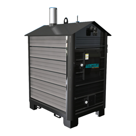
Page 10: Features
FEATURES Identifying Main Components (see item list on page 9) Pro Series 100 Pro Series 200/400 EMPYRE PRO SERIES INSTALLATION AND OPERATION MANUAL • 2009... -
Page 11: Installation
Ash Rake dealer for details. Fork Lift Lifting Guides Drain Installation Requirements Junction/Receptacle Box 1. The Empyre Pro Series furnace must be installed Probe on a level, noncombustible floor pad, such as Snap Disc concrete or patio blocks. Heat Exchange Flues Baffle 2. -
Page 12: Foundation Dimensions
5. Lay down 14-2 underground wire approved for underground installation. Obtain the required electrical permit and confirm local electrical code requirements prior to installation. EMPYRE PRO SERIES INSTALLATION AND OPERATION MANUAL • 2009... -
Page 13: Outdoor Furnace Installation
Add them and round the exhaust, thereafter use the properly insulated total to the nearest 1000 BTU per hour. chimney. 3. Determine whether the space is ‘confined’ or EMPYRE PRO SERIES INSTALLATION AND OPERATION MANUAL • 2009... -
Page 14: Water Line Hookup
(see Figure 4). Electrical Hookup Run wire into junction box. See wiring diagram for details (see page 24). NOTE: The receptacle is provided solely to run the circulating pumps. EMPYRE PRO SERIES INSTALLATION AND OPERATION MANUAL • 2009... -
Page 15: Typical Installation
These drawings should help in establishing a list of material required for a typical installation. All parts should be available from your Empyre Pro Series provider. Ask your dealer for a parts list. EMPYRE PRO SERIES INSTALLATION AND OPERATION MANUAL • 2009... -
Page 16: Hookup To The Existing Heat System (Water To Air)
For garage or shop, wire pump through an in-line thermostat. 2. Each zone can be manually adjusted with the restrictor valves on the supply header. 3. Adjust mixing valve to run supply water temperature between 110˚F - 120˚F (43˚C - 49˚C) in concrete floor installation. Figure 3 EMPYRE PRO SERIES INSTALLATION AND OPERATION MANUAL • 2009... -
Page 17: Side Arm Installation
To top of hot water tank Figure 2 Stainless Steel Water to Water Heat Exchanger, Figure 2, can be used in place To domestic of a side arm. heating system Hot water in from Pro Series furnace From bottom of hot water tank EMPYRE PRO SERIES INSTALLATION AND OPERATION MANUAL • 2009... -
Page 18: Auxiliary Heat (Water To Water)
Note: The existing furnace functions as a standby. automatically cuts in when the Empyre Pro Series The aquastat on an in-house furnace should be Outdoor Furnace runs out of wood, Figure 3. turned lower than the aquastat at the Empyre Pro Series. EMPYRE PRO SERIES INSTALLATION AND OPERATION MANUAL • 2009... -
Page 19: Baseboard Distribution
24 V Transformer From pool or spa From furnace Common Header Set Up Pump can be wired through an in-line thermostat. Each zone can be manually adjusted with the ball valves on the supply header. Adjust mixing valve to run entering water temperature between 110°F - 120°F (43°C - 49°C) in concrete floor installations. EMPYRE PRO SERIES INSTALLATION AND OPERATION MANUAL • 2009... -
Page 20: First Fill
(See pg WOOD INTO THE FIREBOX! 8 No.22). Turn on the water and open drain valve. NOTE: The Empyre Pro Series has been pressure tested at the factory for water leaks. Some condensation Check all lines and connectors for leaks. may be observed in the firebox while the furnace is heating after the water has become completely cold. -
Page 21: Understanding The Gasification Process
7 inches in the Pro Series 400. It is good to mix the dry and wet wood when possible. When using the recommended seasoned wood where the moisture EMPYRE PRO SERIES INSTALLATION AND OPERATION MANUAL • 2009... -
Page 22: Cleaning Out Ash
When ignited this creosote makes an extremely 3. Reach the ash rake to the back of the chamber and hot fire. To reduce the amount of creosote, a small pull ash forward into a steel container. EMPYRE PRO SERIES INSTALLATION AND OPERATION MANUAL • 2009... -
Page 23: Fire Brick & Insulation
Do not carelessly throw heavy pieces of wood onto the brick. Power Outages Gently rake ashes out of secondary burn The Empyre Pro Series furnace, unlike a gas or chamber. oil fired appliance, does not stop generating heat when the power is interrupted even though the 3. Do not damage brick while stirring the fire. -
Page 24: Maintenance
Note the small air holes at dealer for authorized supplies. It is the responsibility each of the brick slots. Ensure that air is free to flow to of the owner to maintain yearly water sample results each air hole. Also inspect the vertical air tube, if there on file. EMPYRE PRO SERIES INSTALLATION AND OPERATION MANUAL • 2009... -
Page 25: Reference
DTS Display Messages In normal operation, the probe temperature will be shown on the display. In case of an alarm or error, the following messages will be shown: Er = Memory error - - = Short-circuit probe error ∞ = Open probe error EMPYRE PRO SERIES INSTALLATION AND OPERATION MANUAL • 2009... -
Page 26: Hot Water Wood Furnace Wiring Diagram - Empyre Pro Series 200 And 400
REFERENCE Hot Water Wood Furnace Wiring Diagram - Empyre Pro Series 100, 200 and 400 CAUTION DO NOT CONNECT THE ELECTRICAL COMPONENTS OF THIS UNIT TO ANY OTHER ELECTRICAL APPLIANCE. EMPYRE PRO SERIES INSTALLATION AND OPERATION MANUAL • 2009... -
Page 27: Furnace Specifications
Order replacement parts through your local dealer. Identify parts by referring to components on pages 8, 9 and 24. Replacement parts must be purchased through Pro-Fab Industries by your local dealer in order to maintain the furnace warranty. EMPYRE PRO SERIES INSTALLATION AND OPERATION MANUAL • 2009... -
Page 28: Troubleshooting
Place logs centered over all the brick slots/ incorrect length and loading. air passages on the firebox floor. Note: If one brick slot is left with no wood the air bypasses the wood and exits through this slot. EMPYRE PRO SERIES INSTALLATION AND OPERATION MANUAL • 2009... -
Page 29: Troubleshooting
Possible buildup on the door frame socket). With ash rake scrape door bottom. frame bottom. Wood is too wet. Burn only seasoned wood. Furnace is not sitting level. Level furnace. EMPYRE PRO SERIES INSTALLATION AND OPERATION MANUAL • 2009... -
Page 30: Warranty
Installation and Operation Instruction Manual (see page curred due to faulty installation, operation or maintenance; e) Any cost 22); c) The Empyre Pro Series Furnace has been altered in any way; d) incurred for replacing or repairing of parts not manufactured by Pro- Any material other than Pro-Fab approved fuel has been used;...