Panasonic UB-7325 Installation Manual
Electronic board
Hide thumbs
Also See for UB-7325:
- Operating instructions manual (44 pages) ,
- Operating instructions manual (28 pages)
Table of Contents
Advertisement
Quick Links
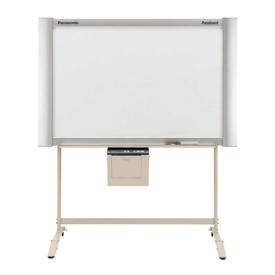
[Stand (option)]
[Wall-mounting (option)]
Stand and Wall-mounting kit are optional.
• Please ask your dealer regarding assembly of the electronic board and instruction for wall-mounting.
Before installing this set, please read this manual completely.
Electronic Board
Installation Manual
(for qualified service personnel)
English . . . . . . . . . . . . . . . . .
Français . . . . . . . . . . . . . . . . 17- 32
Deutsch . . . . . . . . . . . . . . . . 33- 48
Español . . . . . . . . . . . . . . . . 49- 64
Italiano . . . . . . . . . . . . . . . . . 65- 80
Nederlands. . . . . . . . . . . . . . .81- 96
Svenska . . . . . . . . . . . . . . . . .97-112
中 文 . . . . . . . . . . . . . . . . . .113-128
Русский . . . . . . . . . . . . . . . .129-144
UB-7325
Model No.
1- 16
Advertisement
Table of Contents

Related Manuals for Panasonic UB-7325


Summary of Contents for Panasonic UB-7325
- Page 1 [Stand (option)] [Wall-mounting (option)] (for qualified service personnel) Stand and Wall-mounting kit are optional. UB-7325 Model No. English ....1- 16 Français ....17- 32 Deutsch .
-
Page 2: Table Of Contents
Table of Contents page Assembling the Electronic Board ......3 ●Accessories for assembling ....... . 3 ●Assembly . -
Page 3: Assembling The Electronic Board
Assembling the Electronic Board ■ Accessories for assembling The package includes the parts for setting up the electronic board shown below. Make sure that all of these parts are included in the package before proceeding. Part Name Illustration Q’ty Remarks Power cord For wall-mounting Wall-mounting... -
Page 4: Assembly
Assembling the Electronic Board ■ Assembly Assemble the optional stand or wall-mounting kit. ■ If you are using a stand, refer to page 9. ■ If you are using a wall-mounting kit, refer to page 13. Remove the electronic board from the shipping box. Remove the joints, then remove the electronic board from the shipping box. - Page 5 Assembling the Electronic Board ■ Using the wall-mounting kit (option) Install the electronic board. 1) Hang the electronic board on the optional wall- Install the electronic board using the stand (option) mounting fixtures. or wall-mounting kit (option). ■ Using the stand (option) 1) Hang the electronic board on the optional stand.
-
Page 6: Electronic Board Operations Check
Assembling the Electronic Board Connect the power cord. Check operations. 1) Securely fit the supplied power cord into the Refer to “Electronic Board Operations AC inlet on the printer unit. Check” on page 7. 2) Fit the power cord into the cable holder. Cable holder Wipe the screen film surface. -
Page 7: Electronic Board Operations Check
Electronic Board Operations Check After assembling the electronic board, perform the procedures presented in the following table to make sure it functions properly. Points to Check Step Symptom Solutions Turn on the power switch. “ ” flashes after “ ” lights up. (Normal operation) (If not) Check power cord. -
Page 8: Repacking
Repacking Perform Assembly Steps 2 through 4 on pages 4 - 6 in reverse to repack the electronic board and accessories. Use the joints to fasten the shipping box. Shipping box Thermal transfer film Power cord Markers Eraser Manuals, CD-ROM Joints Electronic board Joints... -
Page 9: Assembling The Optional Stand (Kx-B061)
Assembling the Optional Stand (KX-B061) ■ Accessories The package box for the optional stand includes the parts noted below; please confirm that all parts are present before beginning installation Part name Illustration Q’ty Part name Illustration Q’ty Stand base Wing bolt M5 x 12 mm ( ”) Support... -
Page 10: Assembly
Assembling the Optional Stand (KX-B061) ■ Assembly Assembling the stand ■ Assembling the fall-prevention extension legs The fall-prevention extension legs increase the safety of the electronic board. • Caster locks are attached to Fall-prevention extension legs the back side. Caution •... - Page 11 Assembling the Optional Stand (KX-B061) ■ Assembling the stand Assemble with the holes toward the front. Pull the fall-prevention extension legs Locking down (fall-prevention extension legs casters side will be fixed by the lock pin.) (rear) Locking casters side (rear) Note Do not tighten the screw too much.
- Page 12 Assembling the Optional Stand (KX-B061) Attach the fixtures with the four wing-bolts. Assemble and install the electronic board. Refer to page 4.
-
Page 13: Optional Wall-Mounting Kit (Kx-B063)
UB-7325 is 215 kgf (474 lbs.). 2. The position of the intended installation is of adequate size for the selected Panaboard. UB-7325 is 1,516 mm (H) × 1,648 mm (W) [5' (H) × 5' 5" (W)]. 3. An outlet is within 3 m (9' 10 "... -
Page 14: Wall-Mounting Procedure
Caution The wall must be capable of supporting at least 2,108N [215 kgf (474 lbs.)] for UB-7325. Tape the Wall-mounting template on the wall. • Do not use the template included in the wall-mounting kit (KX-B063), but rather the one included with the electronic board (UB-7325). -
Page 15: Attaching The Wall-Mounting Fixtures
Optional Wall-mounting Kit (KX-B063) ■ Attaching the wall-mounting fixtures The electronic board must be mounted with the method most suited to the material of the wall. Three methods are presented here. (Other options may be available in your area.) ● Attaching to metal or concrete walls Stud plugs (sold in stores) are needed. - Page 16 Optional Wall-mounting Kit (KX-B063) ● Attaching to plasterboard walls Split-wing toggles (sold in stores) are needed. Split-wing toggle Insert each bolt through a hole Wall-mounting in the wall-mounting fixture and Plasterboard fixture into the hole in the wall beneath so that the arms of the split- Bolt wing toggle are horizontal.