Table of Contents
Advertisement
Installation Manual Included (for qualified service personnel)
• To assemble this unit, please refer to the Installation Manual on pages 37 through 60.
• Before operating this unit, please read these instructions completely and keep them carefully for future
reference.
• This unit is designed for installation by a qualified servicing dealer.
Installation performed by non-authorized individuals could cause safety-related problems with the operation of
this equipment.
For U.S.A. only:
• To locate the closest authorized dealer in your area, please call 1-800-449-8989.
Operating Instructions
(For Basic Operations)
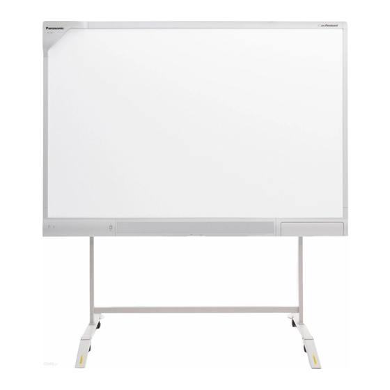
UB-T781
Stand is sold separately.
Electronic Board
(elite Panaboard)
UB-T781
Model No.
UB-T781W
UB-T761
Advertisement
Table of Contents

Related Manuals for Panasonic UB-T781


Summary of Contents for Panasonic UB-T781
-
Page 1: Operating Instructions
Installation performed by non-authorized individuals could cause safety-related problems with the operation of this equipment. For U.S.A. only: • To locate the closest authorized dealer in your area, please call 1-800-449-8989. Operating Instructions (For Basic Operations) Electronic Board (elite Panaboard) Model No. UB-T781 Stand is sold separately. UB-T781 UB-T781W UB-T761... - Page 2 Introduction Introduction Thank you for purchasing the Panasonic Electronic Board. For optimum performance and safety, please read these instructions carefully. Feature Highlights By connecting the elite Panaboard to a computer and using a projector to display the contents of the computer’s screen on the elite Panaboard, you can do the following.
- Page 3 Things you should keep a record of Attach your sales receipt here For your future reference Date of purchase Serial number Dealer’s name Dealer’s address Dealer’s tel no. About the Operating Instructions There are 2 separate operating manuals for the elite Panaboard. For Basic Operations (this document) For Software...
- Page 4 Introduction Abbreviations Windows refers to the Microsoft ® Windows 2000 refers to the Microsoft ® Windows XP refers to the Microsoft ® Windows Vista refers to the Microsoft ® DirectX refers to the Microsoft ® Trademarks • Microsoft, Windows, Windows Vista, DirectX, and Windows Media are either registered trademarks or trademarks of Microsoft Corporation in the United States and/or other countries.
-
Page 5: System Requirements
Warning about saving data When the system storage device or any of its optional storage device is adversely effected by operational errors, static electricity, electrical noise, vibration, dust or when the power has been cut off due to malfunction, repair or inadvertently, the memory contents may be lost or changed. Before operating the system, make a point of reading the precautionary notes in the Operating Instructions and the help information, and observe them during operation. - Page 6 Introduction Exemption of Liability Panasonic Communications Co., Ltd. is not responsible for accidents or injuries caused by, but not limited to, the following: Altering the device or improper installation construction. Using the device for purposes beyond its intended use. Earthquake, fire, flood, tidal wave, hurricane, lightning or other natural phenomena.
-
Page 7: Table Of Contents
Table of Contents For Your Safety ...8 For Your Safety ...8 For Users ...8 Safety Information (For United Kingdom Only) ...11 Precautions ...12 Warning Label ...13 Usage ...14 Included Accessories ...14 Names and Uses of the Parts ...15 Connecting External Components ...18 Installing the elite Panaboard software ...22 Setting the Projector ...23 Setting Your System (Calibration) ...24... -
Page 8: For Your Safety
For Your Safety For Your Safety To prevent severe injury and loss of life, read this section carefully before using the unit to ensure proper and safe operation of your unit. • This section explains the graphic symbols used in this manual. - Page 9 Plug the power cord firmly into an AC outlet. Otherwise, it can cause fire or electric shock. Do not pull, bend, rest objects on, or chafe the power cord and plug. Damage to the power cord or plug can cause fire or electric shock.
- Page 10 For Your Safety Make sure that the battery is installed with the correct polarity as indicated on the battery holder. Incorrectly installed batteries may burst or leak, resulting in injuries. Batteries that seem worn down or damaged should not be used. Using worn down or damaged batteries may result in leaking.
-
Page 11: Safety Information (For United Kingdom Only)
If you lose the fuse cover, the plug must not be used until a replacement cover is obtained. A replacement fuse cover can be purchased from your local Panasonic Dealer. IF THE FITTED MOULDED PLUG IS UNSUITABLE FOR THE SOCKET OUTLET IN YOUR PREMISES, THEN THE FUSE SHOULD BE REMOVED AND THE PLUG CUT OFF AND DISPOSED OF SAFELY. -
Page 12: Precautions
For Your Safety As the colours of the wire in the mains lead of this apparatus may not correspond with the coloured markings identifying the terminals in your plug, proceed as follows. The wire that is coloured GREEN-AND-YELLOW must be connected to the terminal in the plug which is marked with the letter E or by the Earth symbol or coloured GREEN or GREEN-AND-YELLOW. -
Page 13: Warning Label
For Your Safety Warning Label WARNING: TO PREVENT ELECTRIC SHOCK, DO NOT REMOVE COVER. NO USER-SERVICEABLE PARTS INSIDE. REFER SERVICING TO QUALIFIED SERVICE PERSONNEL. PBQAA0582ZA Operating Instructions (For Basic Operations) -
Page 14: Usage
Usage Included Accessories Check that all of the following items are included with your elite Panaboard. In the event that an item is missing, please contact your dealer. List of Accessories Power Cord (3 m [9 ft. 10 in.]) AAA Battery (LR03) (Disposable) Operating Instructions (For Basic Operations) -
Page 15: Names And Uses Of The Parts
Names and Uses of the Parts Screen Front View Position Sensor Detects the position of the electronic pen. Do not block the sensor while operating the elite Panaboard. Screen Board Project the contents of a computer screen using a projector. Power Switch Pen Tray Push the center of the door to open the pen tray,... - Page 16 Usage Rear View Notice • The elite Panaboard is designed exclusively for projector images. Do not write on the screen board with a white-board marker. • The operation of external devices connected via the USB hub is not guaranteed. • External devices connected via the USB hub that require a lot of power, such as scanners or CD/ CD-Rs, may not operate properly.
- Page 17 Notice • Use the electronic pen by holding it at a right angle to the screen board. Holding it at an angle can cause its position to be read incorrectly. • Do not use multiple pens at the same time. This can result in erroneous operation. •...
-
Page 18: Connecting External Components
Usage Connecting External Components Set the power switch to "O" (OFF), connect the power cord (included) to the elite Panaboard, and plug the power cord into an AC outlet. Power Cord (Included) • Plug the power cord into an outlet that is close to the elite Panaboard and in a location that is easy to unplug. - Page 19 Connect the elite Panaboard to a computer using the USB cable (included). • elite Panaboard: Plug the B connector (smaller connector) into the elite Panaboard's USB port. Computer: Plug the A connector (larger connector) into a USB port on the computer. •...
- Page 20 Usage Connecting External Devices Connect the external device to the elite Panaboard using a USB cable (sold separately). • elite Panaboard: Plug the A connector (larger connector) into the elite Panaboard’s USB port. External device: Plug the B connector (smaller connector) into a USB port on the external device. To USB Port About the Usage Location •...
- Page 21 Volume Control • The volume of the USB speaker on the elite Panaboard can be controlled using the Volume Dial, the volume of Windows, and the volume of the application being used. To adjust the volume, use the Volume Dial, or adjust the volume of the application.
-
Page 22: Installing The Elite Panaboard Software
When installation has finished, click [Finish]. • Restart your computer if you are prompted to do • The group [elite Panaboard] will be created in the [Panasonic] group in the program menu. • The following items will appear in the [elite Panaboard] group: –... -
Page 23: Setting The Projector
The electronic pen may not function correctly within 50 mm (2 in.) of the position sensor in the upper-left corner of the screen board. UB-T781 / UB-T761 5 mm ( in.) 50 mm (2 in.) -
Page 24: Setting Your System (Calibration)
Usage • If the image is projected trapezoidally, the position of the electronic pen may not be read correctly. Adjust the projector so that the projected image is a rectangle. Refer to your projector's documentation for information on adjusting the projected image. Set the Proper Resolution •... -
Page 25: Starting The Elite Panaboard Software And Performing Calibration
Starting the elite Panaboard software and Performing Calibration Turn on the elite Panaboard. Connect the elite Panaboard to your computer with the USB cable. • The elite Panaboard software starts automatically. • When you start the elite Panaboard software for the first time, the calibration screen is displayed. -
Page 26: Uninstalling The Elite Panaboard Software
Select [Add or Remove Programs] from the Control Panel. • In Windows 2000, select [Add/Remove Programs], and in Windows Vista, select [Uninstall a program]. Select Panasonic elite Panaboard, then remove Follow the on-screen instructions. When uninstallation is complete, restart your computer. -
Page 27: Viewing The Electronic Documentation
"Operating Instructions (For Software)". Turn on your computer and start Windows. Open "Operating Instructions (For Software)" from the Start menu. ([Start] ® [All Programs] ® [Panasonic] ® [elite Panaboard] ® [Operating Instructions for Software]) • The electronic documentation will be displayed. -
Page 28: Appendix
Appendix Daily Care When cleaning the elite Panaboard or inside the elite Panaboard, make sure to switch off the power and unplug the power cord from the AC outlet. Cleaning the elite Panaboard Gently wipe the elite Panaboard with a soft, moist cloth. Notice •... -
Page 29: Replacing The Penpoint Of The Electronic Pen
Appendix Replacing the Penpoint of the Electronic Pen As the penpoint of the electronic pen becomes worn, a hole will appear in the penpoint. Continuing to use the electronic pen in this condition can cause damage to the screen or unsatisfactory operation, so replace the penpoint with a new one as soon as possible. -
Page 30: Troubleshooting
Appendix Troubleshooting When experiencing problems, please refer to the table below for possible solutions. If the problem persists, contact your dealer. Symptom The LEDs do not light when the power switch is turned on. Red LED is blinking. The computer does not recognize the elite Panaboard. - Page 31 Symptom The message "The pen The electronic pen’s battery is weak. battery is low. Replace the → battery soon." is displayed Replace the electronic pen’s battery. on the computer screen. Because the elite Panaboard is designed exclusively for projector Marks written with a images, you cannot erase the marks with a standard eraser.
-
Page 32: Specifications
LR03 (AAA alkaline dry cell battery) × 1 30 hours (when used continuously at 25 °C [77 °F]) * When using Panasonic LR03 alkaline dry-cell batteries. Input level: 309 mVrms (1 KHz, 0 dB, 10 kW) Stereo 1 system, ø 3.5 mm ( 2 W + 2 W (maximum 4 W + 4 W) in.) stereo mini jack... - Page 33 Screen Board Size: Height ´ Width Interactive Effective Area: Height ´ Width Features UB-T781 1,340 mm ´ 1,752 mm ´ 89 mm in. ´ 5 ft. 9 in. ´ 3 (4 ft. 4 in.) 27 kg (59.52 lbs) 1,175 mm ´ 1,692 mm in.
- Page 34 Appendix Model Number General External Dimensions: Height ´ Width ´ Depth Weight Screen Board Size: Height ´ Input Unit Width Interactive Effective Area: Height ´ Width Features Operating Instructions (For Basic Operations) UB-T781W 1,340 mm ´ 1,899 mm ´ 89 mm in.
- Page 35 Model Number General External Dimensions: Height ´ Width ´ Depth Weight Input Unit Screen Board Size: Height ´ Width Interactive Effective Area: Height ´ Width Features UB-T761 1,142 mm ´ 1,489 mm ´ 89 mm (3 ft. 9 in. ´ 4 ft. 10 in.
-
Page 36: Supplies & Accessories
Appendix Supplies & Accessories Optional Device KX-B061 is not available for the UB-T761. • To purchase separately sold items, contact your dealer. Operating Instructions (For Basic Operations) Electronic Pen Stand Stand Install-Free Kit UE-608025 KX-B061 UE-608030 UE-608050... -
Page 37: Installation Manual
Before constructing or installing the elite Panaboard, please read "Installation Manual (for qualified service personnel)" carefully. Especially, please read "For Your Safety" carefully and install the elite Panaboard safely. Panasonic Communications Co., Ltd. cannot be held responsible for accidents or damage to property resulting from incorrect installation. •... - Page 38 Installation Manual Have the unit installed, removed and disposed of only by qualified service personnel. Operating Instructions (For Basic Operations) CAUTION After installing or moving the electronic board, lock the casters and set the fall-prevention extension legs. Locking the casters (Push this side) Push to lock If the unit is hung on a wall, confirm the...
-
Page 39: Included Accessories
Included Accessories Confirm that the following items are included with the elite Panaboard. Part Name Power Cord (3 m [9 ft. 10 in.]) USB Cable (5 m [16 ft. 4 in.]) CD-ROM Cable Holder Wall Mounting Plate (Left) Wall Mounting Plate (Right) Battery (LR03 AAA alkaline battery) Electronic Pen... - Page 40 Installation Manual Part Name Warranty Notice • Screws (8 count) for wall mounting are not included. Please purchase screws with a size of M6, appropriate for your type of wall (page 45). Operating Instructions (For Basic Operations) Illustration Q’ty Remarks May not be included depending on country/ area.
-
Page 41: Wall Mounting Construction
Wall Mounting Construction Checking the Wall When mounting on a wall, consult with your building's owner, caretaker or construction manager to determine if the wall strength is sufficient to install the elite Panaboard. For safety, install the elite Panaboard only after thoroughly understanding the type of walls, the appropriate types of screws and the construction method (Page 45). -
Page 42: Installing The Wall Mounting Plates
Ensure that the wall is strong enough to support the elite Panaboard. Rated strength: greater than 1,373 N (140 kgf) Using the measuring tape and level, mark the 8 locations to insert the screws. UB-T781 469.5 mm (1 ft. 6 in.) - Page 43 (2 ft. 6 in.) in.) 30 mm (1 in.) 44 mm (1 in.) 40 mm (1 UB-T781 / UB-T781W: 982 mm (3 ft. 2 UB-T761: 784 mm (2 ft. 6 30 mm (1 Operating Instructions (For Basic Operations) Installation Manual in.) in.)
- Page 44 Installation Manual Mount the elite Panaboard on the wall. See "Assembling the elite Panaboard" (For Wall Mounting ® page 52). Operating Instructions (For Basic Operations)
-
Page 45: Wall Types And Installation Procedures
Wall Types and Installation Procedures The method for attaching the wall mounting plates to the wall will vary depending on the wall's structure. Three available options are listed below. Other methods may be necessary depending on the wall. Metal or Concrete walls Stud plugs (not included) are needed. - Page 46 Installation Manual Plasterboard walls Split-wing toggles (not included) are needed. Split-wing toggle Plasterboard Arms Arms Wooden walls Wood screws (not included) are needed. Wooden wall Operating Instructions (For Basic Operations) Bolt Wall mounting plate Wood screw Insert the bolt through the hole in the wall mounting plate and into the hole in the wall so that the arms of the split-wing toggle are horizontal.
-
Page 47: Stand Assembly (Sold Separately)
Stand Assembly (Sold Separately) Included Parts Check that the following parts are included with the stand (KX-BP061). Part Name Stand Base Support Beam Cross Bar (A) Cross Bar (B) Screw (M6 ´ 45 mm [1 Two-wing Bolt (M5 ´ 12 mm [ Support Bracket Fall-prevention Extension Leg Screw (M6 ´... -
Page 48: Assembly Instructions
Installation Manual CAUTION Before assembly, be sure to lock the casters. Locking the casters (Push this side) Assembly Instructions Assemble the fall-prevention extension legs. Operating Instructions (For Basic Operations) - Page 49 Assemble the stand. Notice • Do not over-tighten the screw ( ). (Doing so can warp the support beams.) • Assemble the stand so that the locking casters are on the rear side. Assemble with the holes toward the front. REAR Locking caster side...
- Page 50 Installation Manual Pull the fall-prevention extension legs down. Note • When folding back the fall-prevention extension legs, release the lock as follows ( Mount the elite Panaboard. See "Assembling the elite Panaboard" (For Mounting on a Stand (Sold Separately) ® page 55). Operating Instructions (For Basic Operations)
-
Page 51: Assembly Instructions
Assembly Instructions Preparing for Removing the elite Panaboard from Its Packaging Open the box, remove the accessory box & packing foam and open the plastic sheet of the elite Panaboard. Notice • When handling the screen board, hold it by the edge frame and not the screen board itself. (Holding the screen board can result in damage.) •... -
Page 52: Assembling The Elite Panaboard
Installation Manual Assembling the elite Panaboard For Wall Mounting Loosely wrap the power cord with the cable tie, and plug the power cord into the AC inlet. • Connect the power cord to the elite Panaboard before installing on a wall. Power Cord Insert the end of the cable tie into the cable tie fastening hole behind the control-power... - Page 53 Remove the screw (A) of the attachment cover (B), which is fixed to the attachment board, and slide the attachment cover down. Ensure that the attachment cover and the screw hole (C) of the board attachment are aligned. After unscrewing the attachment cover screws (A), fix them in the holes after sliding the attachment cover down, as shown in the right-sided illustration above.
- Page 54 Installation Manual Disconnect the 2 connectors from the audio board (D). Fasten to the wall. Fasten the lower portion of the board attachment securely to the wall. Operating Instructions (For Basic Operations) Connect the 2 connectors of the USB speaker to the audio board (D).
- Page 55 Wipe the screen board surface. Gently wipe the screen board surface with a soft, moist cloth. Notice • Do not use thinner, benzene, or abrasive chemicals to clean. (Doing so can result in discoloration.) • Do not wipe the screen board with a dry cloth.
- Page 56 Installation Manual Hang the elite Panaboard on the stand with the screw heads. Secure the elite Panaboard to the stand frame using the two-wing bolts (M5 ´ 12 mm [ [2 count]) included with the stand. Note • After installation is complete, use the included cable holder to manage the power cord and USB cable.
-
Page 57: Confirming The Elite Panaboard Operation
Confirming the elite Panaboard Operation After assembling the elite Panaboard, confirm that it operates properly by following the procedure below. Action Turn on the power. Green LED lights. Green LED does not light, or red LED is blinking. Confirming the Interactive Features Following the procedure in "Installing the elite Panaboard software"... -
Page 58: Repackaging
Installation Manual Repackaging To repackage the elite Panaboard, perform steps in "Assembling the elite Panaboard" (For Wall Mounting ® page 52, For Mounting on a Stand (Sold Separately) ® page 55) in reverse. Package the unit as depicted in the diagram in "Preparing for Removing the elite Panaboard from Its Packaging" (page 51). Notice •... -
Page 59: Attaching The Install-Free Kit (Sold Separately)
Attaching the Install-Free Kit (Sold Separately) Attaching the Install-Free Kit Unscrew the 4 screws from the front lower frame cover. Lift the bottom of the front lower frame cover to remove it. Note • The main unit and the USB speakers on the front lower frame cover are connected with the cable. - Page 60 Installation Manual Disconnect the black cable and the white cable from the clamper (B). Unscrew the 7 screws and remove the hub PCB shield plate. Attach the install-free kit to the main unit as shown below. Operating Instructions (For Basic Operations) Attach the hub PCB shield plate to the main unit using the 7 screws and fix the black cable and white cable to their previous positions using the...
- Page 61 Notes Operating Instructions (For Basic Operations)
- Page 62 Notes Operating Instructions (For Basic Operations)
- Page 63 Notes Operating Instructions (For Basic Operations)
- Page 64 This symbol might be used in combination with a chemical symbol. In this case it complies with the requirement set by the Directive for the chemical involved. Panasonic Communications Company of North America Unit of Panasonic Corporation of North America One Panasonic Way, Secaucus, New Jersey 07094 Panasonic Canada Inc.