Table of Contents
Advertisement
Quick Links
Advertisement
Chapters
Table of Contents
Troubleshooting

Related Manuals for Ricoh B234


Summary of Contents for Ricoh B234
-
Page 1: Service Manual
B234/B235/B236 D101/D102/D103 SERVICE MANUAL (Book 1 of 2) 002671MIU MAINFRAME... - Page 5 B234/B235/B236 D101/D102/D103 SERVICE MANUAL BOOK 1 OF 2 MAINFRAME 002671MIU...
- Page 7 It is the reader's responsibility when discussing the information contained within this document to maintain a level of confidentiality that is in the best interest of Ricoh Americas Corporation and its member companies. NO PART OF THIS DOCUMENT MAY BE REPRODUCED IN ANY FASHION AND DISTRIBUTED WITHOUT THE PRIOR PERMISSION OF RICOH AMERICAS CORPORATION.
- Page 9 Ricoh Technical Training Program. Untrained uncertified users utilizing information contained in this service manual to repair or modify Ricoh equipment risk personal injury, damage to property or loss of warranty protection. Ricoh Americas Corporation...
- Page 11 LEGEND PRODUCT COMPANY CODE GESTETNER LANIER RICOH SAVIN B234 DSm790 LD190 Aficio MP9000 8090 B235 DSm7110 LD1110 Aficio MP1110 8110 B236 DSm7135 LD1135 Aficio MP1350 8135 D101 Pro 906EX Pro 906EX Aficio Pro 906EX Pro 906EX D102 Pro 1106EX Pro 1106EX...
-
Page 13: Table Of Contents
Top View....................1-4 Side Views ....................1-4 1.1.5 POWER REQUIREMENTS ...............1-6 1.2 BEFORE YOU BEGIN… ................1-7 1.2.1 B234/B235/B236 OVERVIEW OF OPTIONAL PERIPHERALS ..1-7 1.2.2 D101/D102/D102 OVERVIEW OF OPTIONAL PERIPHERALS ..1-8 Configuration 1: Booklet Finisher B836..........1-8 Configuration 2: Perfect Binder D391 ...........1-9 1.2.3 SPECIAL POINTS ABOUT INSTALLATION ........1-10 1.3 COPIER (B234/B235/B236/D101/D102/D103).........1-11... - Page 14 BOOKLET FINISHER BK5000 (B836)..........1-91 1.10.1 ACCESSORIES .................1-91 1.10.2 INSTALLATION .................1-92 Docking the Booklet Finisher B836 .............1-94 Connecting the Booklet Finisher B836..........1-96 1.11 FINISHER SR5000 (B830) ..............1-97 1.11.1 ACCESSORIES .................1-97 1.11.2 INSTALLATION .................1-98 Docking the Finisher B830..............1-100 Connecting the Finisher B830............1-103 B234/B235/B236/D101/D102/D103...
- Page 15 Seal Check and Removal ..............1-138 Installation..................1-139 1.15.8 BROWSER UNIT (B828) ............1-141 Accessories ..................1-141 Installation..................1-141 1.15.9 VM CARD TYPE C (B861)............1-142 Accessories ..................1-142 Installation..................1-142 1.15.10 FILE FORMAT CONVERTER (B609) ........1-143 Accessories ..................1-143 Installation..................1-143 1.15.11 USB 2.0 HOST INTERFACE (B825) ........1-145 B234/B235/B236/D101/D102/D103...
- Page 16 2.2.2 ADF ....................2-11 2.2.3 FINISHER SR5000 B830 ..............2-11 2.2.4 PUNCH UNIT PU5000 B831 ............2-11 2.2.5 LCIT RT5000 B832................2-12 2.2.6 MULTI-BYPASS TRAY B833 ............2-12 2.2.7 LCIT RT5010 B834................2-12 2.2.8 COVER INTERPOSER TRAY CI5000 B835 ........2-13 2.2.9 BOOKLET FINISHER BK5000 B836..........2-13 B234/B235/B236/D101/D102/D103...
- Page 17 3.4.1 ADF COVERS .................3-16 3.4.2 ADF ORIGINAL TRAY..............3-17 Original Tray ..................3-17 Original Table Cover ................3-17 Bottom Plate ..................3-17 3.4.3 FEED UNIT AND SEPARATION ROLLER........3-18 3.4.4 FEED BELT..................3-19 3.4.5 PICK-UP ROLLER................3-20 3.4.6 ADF SENSORS................3-21 Entrance Sensor and Length Sensor ..........3-21 Registration Sensor ................3-22 B234/B235/B236/D101/D102/D103...
- Page 18 3.8 DEVELOPMENT AND TONER SUPPLY ..........3-64 3.8.1 DEVELOPMENT UNIT REMOVAL..........3-64 Re-installing the Development Unit.............3-65 3.8.2 TONER HOPPER REMOVAL ............3-66 3.8.3 DEVELOPER REPLACEMENT............3-67 Initializing the TD Sensor ..............3-70 3.8.4 CLEANING THE DOCTOR BLADE..........3-71 3.8.5 DEVELOPMENT ENTRANCE, FRONT, REAR SIDE SEALS..3-74 3.8.6 TONER DENSITY SENSOR ............3-75 B234/B235/B236/D101/D102/D103...
- Page 19 CIS Image Position Adjustment: Normal Paper ........3-115 3.10.19 TANDEM FEED TRAY PAPER SIZE CHANGE....3-116 Setting the Paper Size for the Right Tandem Tray ......3-116 Setting the Paper Size for the Left Tandem Tray......3-117 3.10.20 TANDEM TRAY SIDE REGISTRATION ......3-119 B234/B235/B236/D101/D102/D103...
- Page 20 PSU-E (ENGINE): A, B ............3-165 3.14.6 PPG, CGB POWER PACKS............3-166 3.14.7 AC DRIVE BOARD ..............3-167 3.15 CONTROLLER BOARDS, HDD ............3-168 3.15.1 CONTROLLER BOX COVER ..........3-168 3.15.2 CONTROLLER BOARD, NVRAM..........3-169 3.15.3 INTERFACE BOARD...............3-170 3.15.4 IPU...................3-171 3.15.5 SD CARD UNIT ...............3-172 B234/B235/B236/D101/D102/D103 viii...
- Page 21 4.1.1 OVERVIEW ..................4-1 4.1.2 RECOVERY METHODS ..............4-1 4.1.3 DOWNLOAD ERROR CODES............4-2 4.1.4 PAPER JAM CODES ................4-5 Copier B234/B235/B236 ...............4-6 Paper Jam Locations – Finisher B830 ..........4-7 Cover Interposer Tray B835..............4-7 Booklet Finisher B836................4-8 Paper Jam Locations – Z-Fold Unit B660 ..........4-8 4.2 SERVICE CALL CONDITIONS ..............4-9...
- Page 22 5.5.1 MAIN MACHINE OUTPUT CHECK: SP5804 ........5-178 Main Machine Output Check (SP5-804) ...........5-178 5.5.2 ADF OUTPUT CHECK: SP6008 ...........5-180 5.5.3 FINISHER OUTPUT CHECK SP6113 (B830) .......5-181 5.5.4 BOOKLET FINISHER OUTPUT CHECK: SP6207 ......5-182 5.5.5 COVER INTERPOSER (B835) OUTPUT CHECK: SP6401..5-182 5.6 SMC LISTS.....................5-184 B234/B235/B236/D101/D102/D103...
- Page 23 PRINTER BIT SWITCH SETTINGS..........5-218 DETAILED DESCRIPTIONS SECTION 6. DETAILED DESCRIPTIONS ............6-1 6.1 COMPONENT LAYOUT ................6-1 6.2 PAPER PATH.....................6-2 6.3 COPY PROCESS..................6-3 6.4 DRIVE LAYOUT ..................6-5 6.5 ELECTRICAL COMPONENT DESCRIPTIONS .........6-6 6.5.1 COPIER ENGINE ................6-6 6.5.2 ADF ....................6-17 6.6 ADF ......................6-18 B234/B235/B236/D101/D102/D103...
- Page 24 Settings Adjustable for Each Original Mode........6-53 6.9.6 RELATION BETWEEN THE SP AND UP SETTINGS.....6-54 6.10 LASER EXPOSURE ................6-56 6.10.1 OVERVIEW ................6-56 6.10.2 LASER EXPOSURE MECHANISM ...........6-57 6.10.3 LD SAFETY SWITCHES ............6-58 6.10.4 MULTI-BEAM LINE EXPOSURE ..........6-59 6.10.5 POLYGON MIRROR MOTOR ...........6-60 B234/B235/B236/D101/D102/D103...
- Page 25 Toner Collection Bottle..............6-107 6.14 PAPER FEED ...................6-109 6.14.1 OVERVIEW ................6-109 6.14.2 DRIVE..................6-111 Tray Components (Example: 3rd Tray)..........6-112 Vertical Paper Path ................6-112 6.14.3 PAPER LIFT – TRAYS 2 & 3 ...........6-113 6.14.4 PICK-UP AND FEED – TRAYS 1, 2, 3 ........6-115 xiii B234/B235/B236/D101/D102/D103...
- Page 26 Fusing Temperature Control at Power On (Cold/Warm Starts)..6-152 Fusing Temperature Control During Standby and in Energy Saver Mode6-153 Fusing Temperature Control During Machine Operation ....6-153 Fusing Temperature Control for Low Power Mode (During and Immediately After)................6-157 Low Speed Mode (CPM Down) ............6-157 B234/B235/B236/D101/D102/D103...
- Page 27 What happens in the off mode ............6-186 Returning to stand-by mode..............6-186 Disabling the off mode ..............6-186 6.19.5 SLEEP MODE .................6-187 Entering sleep stand-by and sleep modes ........6-187 What happens in sleep stand-by and sleep modes ......6-187 Returning to stand-by mode..............6-187 B234/B235/B236/D101/D102/D103...
- Page 28 RING BINDER RB5000 (D392)..........7-20 7.1.15 Z-FOLDING UNIT ZF4000 (B660) ..........7-20 7.1.16 D101/D102/D103 MACHINE CONFIGURATION.......7-21 7.1.17 B234/B235/B236 MACHINE CONFIGURATION .......7-22 Z-FOLDING UNIT (B660) SEE SECTION B660 FOR DETAILED TABLE OF CONTENTS FINISHER (B830) SEE SECTION B830 FOR DETAILED TABLE OF CONTENTS LCIT (B832)
- Page 29 COVER INTERPOSER TRAY (B835) SEE SECTION B835 FOR DETAILED TABLE OF CONTENTS BOOKLET FINISHER (B836) SEE SECTION B836 FOR DETAILED TABLE OF CONTENTS xvii B234/B235/B236/D101/D102/D103...
- Page 31 INSTALLATION PREVENTIVE MAINTENANCE REPLACEMENT AND ADJUSTMENT LCIT B832 LCIT B834 TROUBLESHOOTING Z-FOLDING UNIT B660, FINISHER B830 SERVICE TABLES DETAILED DESCRIPTIONS MULTI BYPASS TRAY B833 SPECIFICATIONS COVER INTERPOSER TRAY B835...
-
Page 33: Important Safety Notices
IMPORTANT SAFETY NOTICES PREVENTION OF PHYSICAL INJURY 1. Before disassembling or assembling parts of the copier and peripherals, make sure that the copier power cord is unplugged. 2. The wall outlet should be near the copier and easily accessible. 3. Note that some components of the copier and the paper tray unit are supplied with electrical voltage even if the main power switch is turned off. -
Page 34: Laser Safety
SAFETY AND ECOLOGICAL NOTES FOR DISPOSAL 1. Do not incinerate toner bottles or used toner. Toner dust may ignite suddenly when exposed to an open flame. 2. Dispose of used toner, developer, and organic photoconductors in accordance with local regulations. (These are non-toxic supplies.) 3. - Page 35 Conventions in this Manual This manual uses several symbols. Symbol What it means Refer to section number See Core Tech Manual for details Screw Connector E-ring Clip ring North America EUR/A Europe/Asia LEFSEF.WMF...
-
Page 37: Installation
INSTALLATION INSTALLATION REVISION HISTORY Page Date Added/Updated/New 09/07/2006 Updated Information – Completing the Installation 46 ~ 47 10/09/2007 Updated Information – Adjusting Image Position Sensor 09/07/2006 Updated Information – Key Counter 11/21/2006 Updated Information – MFP Controller Options 03/23/2007 Updated Information – MFP Controller Options 134 ~ 137 02/01/2007 Updated Information –... -
Page 39: Installation Procedures
3) Directly exposed to heat from a heater 7. Do not place the machine where it will be exposed to corrosive gases. 8. Do not install the machine at any location over 2,000 m (6,500 feet) above sea level. B234/B235/B236/D101/D102/D103... -
Page 40: Machine Level
Within 5 mm (0.2") of level 1. Front to back: Within 5 mm (0.2") of level 2. Right to left: NOTE: The machine legs may be raised or lowered in order to level the machine. Set a carpenter’s level on the exposure glass. B234/B235/B236/D101/D102/D103... -
Page 41: Minimum Space Requirements
NOTE: The controller box door [A] and PSU door [B] on the back of the machine swing open and can be removed. Both doors can be removed to allow the machine to pass through a narrow doorway. ( 1.3.4) B234/B235/B236/D101/D102/D103... -
Page 42: Dimensions
1270 (50) 980 (38.6) 800 (31.5) 600 (23.6) 870 (34.3) 850 (33.5) 540 (21.3) 177 (7) d101i 910 164 (6.5) D101I910.WMF Approximate space required (With Booklet Finisher B836) Meters Feet With A3/DLT LCT B833 11.4 With A4/LT LCT B832 10.4 B234/B235/B236/D101/D102/D103... - Page 43 980 (38.6) 800 (31.5) 870 (34.3) 850 (33.5) 540 (21.3) 860 (33.8) 177 (7) d101i 912 164 (6.5) D101I912.WMF Approximate Space Required (All Options with Ring Binder D392) Meters Feet With A3/DLT LCT B833 12.2 With A4/LT LCT B832 11.2 B234/B235/B236/D101/D102/D103...
-
Page 44: Power Requirements
2. Avoid multi-wiring. 3. Be sure to ground the machine. 4. Never set anything on the power cord. Input Voltage Level Machine Area Europe/Asia B234/D101 208~240V 60 Hz Minimum 220~240V 50/60 Hz Minimum 16A B235/D102 B236/D103 Permissible voltage fluctuation: CAUTION Never turn off the main power switch when the power LED is lit or flashing. -
Page 45: Before You Begin
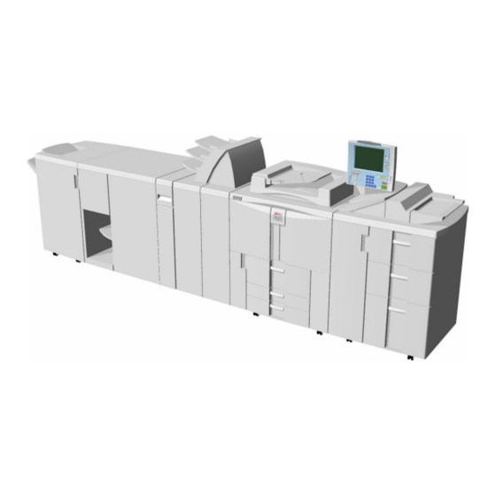
Before You Begin… BEFORE YOU BEGIN… 1.2.1 B234/B235/B236 OVERVIEW OF OPTIONAL PERIPHERALS B833 B234/235/236 Finisher Copier A4/LT LCT A3/DLT LCT Booklet Finisher Cover Interposer Z-Fold Unit B234I412C.WMF There are many peripherals available for this machine. Install them in this order:... -
Page 46: D101/D102/D102 Overview Of Optional Peripherals
• To prevent the Cover Interposer Tray from falling, always install the next peripheral device in line before installing the tray unit of the Cover Interposer Tray. Cover Interposer Tray (Tray Unit) Booklet Finisher BK5000 (B836) Finisher SR5000 (B830) B234/B235/B236/D101/D102/D103... -
Page 47: Configuration 2: Perfect Binder D391
• To prevent the Cover Interposer Tray from falling, always install the next peripheral device in line before installing the tray unit of the Cover Interposer Tray. Cover Interposer Tray (Tray Unit) Finisher SR5000 (B830) B234/B235/B236/D101/D102/D103... -
Page 48: Special Points About Installation
Item Comments 1.3 Copier • First, install the copier ( section 1.3.2). (B234/B235/B236/D101/D102/D103) 1.4 A3/11"x17" Tray Unit (B331-11) 1.5 LCIT RT5000 (B832) The CIS of the image position sensor unit in the LCT must be calibrated at installation for both LCT 1.6 LCIT RT5010 (B834) -
Page 49: Copier (B234/B235/B236/D101/D102/D103)
COPIER (B234/B235/B236/D101/D102/D103) COPIER (B234/B235/B236/D101/D102/D103) 1.3.1 ACCESSORIES B234I001.WMF 1-11 B234/B235/B236/D101/D102/D103... - Page 50 COPIER (B234/B235/B236/D101/D102/D103) Check the quantity and condition of the accessories in the box against the following list: Description Q'ty 1. Operation Panel..............1 2. Lower Cover - Operation Panel Holder ........1 3. Upper Cover - Operation Panel Holder ........1 4.
-
Page 51: Installation
COPIER (B234/B235/B236/D101/D102/D103) 1.3.2 INSTALLATION CAUTION Rating Voltage for Peripherals Make sure to plug the cables into the correct sockets. “Rating Voltage of Output Connector for Accessory: “Rating Voltage of Output Max. DC 24 V” Connector for Accessory: Max. DC 24 V”... -
Page 52: External Tape And Retainers
COPIER (B234/B235/B236/D101/D102/D103) External Tape and Retainers The installation procedure is not packed with the copier. Always bring this service manual with you. CAUTION Before performing the following procedures, make sure that the machine is unplugged from the power source. B234I006.WMF B234I004.WMF... - Page 53 COPIER (B234/B235/B236/D101/D102/D103) B070I005.WMF B234I024.WMF 3. Remove all tape and retainers from under the ADF [A]. 4. Remove A3 paper [B]. 5. Set the leveling shoes [C] (x 4) under the feet [D], then level the machine. 1-15 B234/B235/B236/D101/D102/D103...
-
Page 54: Internal Tape And Retainers: Paper Trays
COPIER (B234/B235/B236/D101/D102/D103) Internal Tape and Retainers: Paper Trays B234I003.WMF B234I019.WMF 1. Pull out the tandem tray (1st tray) completely, remove the tray lock plate [A] ( x 1) and remove the cushion [B]. 2. Push in the right tray of the tandem tray, then remove the cushion [C]. -
Page 55: Internal Tape And Retainers: Fusing Unit
COPIER (B234/B235/B236/D101/D102/D103) Internal Tape and Retainers: Fusing Unit B234I002.WMF B234I002A.WMF 1. Open the front doors and remove all visible tape and retainers from inside the machine [A]. 2. Press down lever D2 [B], pull out the fusing unit [C], and remove all tape and... -
Page 56: Internal Tape And Retainers: Transfer Unit
COPIER (B234/B235/B236/D101/D102/D103) Internal Tape and Retainers: Transfer Unit B234I002B.WMF 1. Lower the lever C1 [A]. 2. Remove all tape, tags, and retainers [B] from the transfer unit ( x1). B234/B235/B236/D101/D102/D103 1-18... -
Page 57: Internal Tape And Retainers: Drum Cleaning Unit
COPIER (B234/B235/B236/D101/D102/D103) Internal Tape and Retainers: Drum Cleaning Unit 1. Open the right front door. 2. Remove the black screws at x3). 3. Take off the inner cover NOTE: These illustrations show removal using the hex driver provided to the customer. - Page 58 COPIER (B234/B235/B236/D101/D102/D103) 6. Remove the faceplate. B234I110A.WMF 7. Pull the purple handle toward you until the drawer stops. NOTE: The development unit will shift slightly to the right as you pull the drawer out. B234i111.WMFF B234/B235/B236/D101/D102/D103 1-20...
- Page 59 COPIER (B234/B235/B236/D101/D102/D103) 8. Remove the drum cleaning unit. • Raise the purple lever and pull the cleaning unit to the left until it disengages the lever • Lift the unit out of the drawer Important: Grasp the cleaning unit by its handles as shown and lift it straight B234I113.WMF...
-
Page 60: Pouring Developer
COPIER (B234/B235/B236/D101/D102/D103) Pouring Developer 1. Lift the development unit [A] by its purple handle and hold it level as you remove it. B234i112.WMFF 2. Remove the shipping tape from the inner cover [B]. RIMGI901.BMPP 3. Place the development unit on the spread paper as shown. - Page 61 COPIER (B234/B235/B236/D101/D102/D103) 4. Remove the bracket [A] ( x1). 5. Disconnect the toner hopper [B] 6. Tilt the hopper slightly when you remove it. B234I902.WMFF 7. Pour the developer into the development unit. • Move the toner packet [C] from side...
- Page 62 COPIER (B234/B235/B236/D101/D102/D103) Reinstalling the Development Unit Important: When you reinstall the development unit, handle it carefully. • Never allow the development roller to hit the OPC drum or any other part of the frame of the development unit drawer. • Scratches or other damage to either...
-
Page 63: Operation Panel
COPIER (B234/B235/B236/D101/D102/D103) Operation Panel B234I012.WMF B234I013.WMFMF 1. Remove the right upper cover [A] ( x 4). 2. Pass the harness [B] through the arm [C]. 3. Install the arm [C] ( x 9). 1-25 B234/B235/B236/D101/D102/D103... - Page 64 COPIER (B234/B235/B236/D101/D102/D103) B234I014.WMF B234I015.WMF 4. Pull the harness [A] through the top of the arm and connect it to the operation panel [B] ( x2). 5. Secure the harness clamp [C] on the operation panel ( x 1, M4 x 6 brass pan head).
-
Page 65: Filters, Original Exit Tray
COPIER (B234/B235/B236/D101/D102/D103) Filters, Original Exit Tray B234I017.WMF B234I016.WMF 1. Install the upper cover [A] ( x 3) 2. Install the lower cover [B] ( x 3). 3. Set the drum dust filter [C]. 4. Loosen the bottom knob, adjust the view angle of the operation panel, then tighten the knob. - Page 66 COPIER (B234/B235/B236/D101/D102/D103) B070I506.WMF B234I018.WMF 6. Set the optics dust filter [A]. 7. Loosen the two screws of the bracket [B]. 8. Attach the original exit tray at [C] ( x 2) and [D] ( x 1) 9. Re-tighten the screws of the bracket [B] ( x 2).
-
Page 67: Testing The Copier Breaker Switch
COPIER (B234/B235/B236/D101/D102/D103) Testing the Copier Breaker Switch 1. Plug the copier power cord into its power source. NOTE: Do not turn on the copier. The copier should be off. 2. Use the tip of a small screwdriver to push the breaker test button. -
Page 68: Initializing The Machine
COPIER (B234/B235/B236/D101/D102/D103) Initializing the Machine Important: • Before you do this procedure, make sure that the front doors of the machine are closed. 1. Plug in the power cord and turn the main switch on. 2. Install the toner bottles. -
Page 69: Connecting The Copier Tray Heaters
COPIER (B234/B235/B236/D101/D102/D103) Connecting the Copier Tray Heaters The machine comes from the factory with the tray heaters already installed but disconnected. Tray heater connection is optional. The heaters should be connected if the location has high humidity. Consult with the customer before connecting the tray heaters. - Page 70 COPIER (B234/B235/B236/D101/D102/D103) To supply power 24 hours a day Doing the connection in the previous procedure assures that power is supplied to the machine for the heaters even after the copier is switched off with the main power switch (for example, in auto off mode). However, with only this connection, the heaters do not operate while the copier is operating.
-
Page 71: Completing The Installation
COPIER (B234/B235/B236/D101/D102/D103) 1.3.3 COMPLETING THE INSTALLATION Setting Paper Sizes for the Paper Trays 1. Set the required paper sizes for all paper trays. Unit Name Setting Copier 1st Tray SP5019 002 2nd Tray Automatic side fence detection. 3rd Tray Automatic side fence detection. -
Page 72: Controller Box, Psu Box Removal
COPIER (B234/B235/B236/D101/D102/D103) 1.3.4 CONTROLLER BOX, PSU BOX REMOVAL Remove the controller box and PSU box only if the machine is too large to pass through a narrow door or passageway. Controller Box Removal B234I904.WMFF B234I905.WMFF 1. Open the controller box [A] ( x 3 with washers). -
Page 73: Psu Box Removal
COPIER (B234/B235/B236/D101/D102/D103) PSU Box Removal 1. Open the PSU box [A] ( x 2). B234I906.WMFF 2. Disconnect ground wire [B] ( x 1). 3. Remove duct [C] ( x 3) 4. Disconnect [D] ( x1). 5. Remove the cover x 3). -
Page 74: Transporting The Copier
COPIER (B234/B235/B236/D101/D102/D103) 1.3.5 TRANSPORTING THE COPIER To prevent blockages in the toner supply path, always follow the procedure below before transporting the copier. If this procedure is not done, SC592 (Toner Bank Motor Error) or SC495 (Toner Bottle Unit Error) may be displayed, requiring replacement of the toner transport hose and coil. -
Page 75: After Moving The Copier
COPIER (B234/B235/B236/D101/D102/D103) After Moving the Copier 1. Turn the main power switch on. 2. Load the toner bottles into the toner bank. 3. Start to supply toner from the toner bank to the toner hopper: 1) Select SP2207 002 (Toner Bank Toner Setup). -
Page 76: A3/11"X17" Tray Unit Tk5000 (B331-11)
A3/11"X17" TRAY UNIT TK5000 (B331-11) 1.4.1 ACCESSORIES B331I001.WMF Check the quantity and condition of the accessories in the box against the following list: Description Q'ty 1. A3/DLT Tray ................1 2. Short Connector................ 1 3. Paper Size Decal ..............1 B234/B235/B236/D101/D102/D103 1-38... - Page 77 [C] ( x 4). 4. Remove the fences and adjust their positions for the paper to be loaded: front fence [D] ( x 1), back fence [E] ( x 1), and end fence [F] ( x 1) 1-39 B234/B235/B236/D101/D102/D103...
- Page 78 5. Open the front doors. 6. Pull out the tandem feed tray [A] completely. 7. Push the right tandem tray [B] into the machine. 8. Remove the left tandem tray [C] ( x 2 left, x 3 right). B234/B235/B236/D101/D102/D103 1-40...
- Page 79 A3/11"x17" Tray Unit TK5000 (B331-11) B331I002A.WMF B331I709.WMF 9. From the left tandem tray, remove the front cover [A] ( x 2). 10. Pull out the right tandem tray [B] then remove it. ( x 2). 1-41 B234/B235/B236/D101/D102/D103...
- Page 80 [D], center rail [E], left rail [F]. NOTE: You must use the short, silver screws on the left and right rails. If you use one of the longer screws, it will block the movement of the tray on the rails. B234/B235/B236/D101/D102/D103 1-42...
- Page 81 13. Re-install the front cover [A] ( x 2). 14. Use SP5019 002 to select the paper size for Tray 1 (A3 or DLT). 15. After selecting the paper size, switch the machine off and on to change the indicator on the operation panel. 1-43 B234/B235/B236/D101/D102/D103...
-
Page 82: Lcit Rt5000 (B)
6. Upper Joint Pins ............... 2 7. Philips Screw - M4 x 8 .............. 1 Installation Procedure – English (not shown)........1 NOTE: The tab paper end fence (3) is located in the LCT unit, mounted on hooks behind the front door. B832I101.WMF B234/B235/B236/D101/D102/D103 1-44... -
Page 83: Lcit Rt5000 (B832)
Unplug the power cord before starting the following procedure. 1. Remove the visible tape and other items [A] from the covers and left side of the LCT. 2. Open the LCT door and remove the shipping retainers and tape [B] holding the levers. 1-45 B234/B235/B236/D101/D102/D103... - Page 84 3. Remove the covers [A] from the right upper side. 4. Remove the covers [B] from the right lower side. 5. Install the pins with the grooved rings [C] on the right upper cover. 6. Install the other pins [D] on the right lower cover. B234/B235/B236/D101/D102/D103 1-46...
- Page 85 9. Turn over the ground plate and use the screws to fasten it to the same holes as shown ( x 2). Important! • If you are going to install the Multi Bypass Tray B833, it must be installed before the LCT is docked to the mainframe. ( 1.7) 1-47 B234/B235/B236/D101/D102/D103...
- Page 86 15. Fasten screw [C] to lock the LCT to the side of the copier. 16. Attach connector [D]. 17. Insert the leveling shoes [E] (x 3) under the leveling feet and level the LCT. 18. Attach the appropriate decals to the trays. B832I108.WMF B234/B235/B236/D101/D102/D103 1-48...
-
Page 87: Adjusting Image Position Sensor Strength And Side-To-Side Registration
20 and 40, the CIS may be defective. 9. Exit the SP mode and turn OFF the main power switch. 10. Remove the paper from the machine. 11. Reattach the LCT to the side of the copier. 12. Turn ON the main power switch. 1-49 B234/B235/B236/D101/D102/D103... -
Page 88: Cis Image Position Adjustment: Normal Paper (Lcit)
19. Exit the SP mode. Push [User Tools]> [Adjust Settings for Operators]. 20. Do SP1911 again (CIS Image Position Adjustment: Feed Setting) and reset the values for Trays 4, 5, 6, and 7 to "1" (ON). 2 mm B234I999.WMF B234/B235/B236/D101/D102/D103 1-50... -
Page 89: Lct B832 Tray Heaters
LCIT RT5000 (B832) 1.5.4 LCT B832 TRAY HEATERS Accessories Description 1. Relay Harness ............. 1 2. Heaters ................ 2 3. Cover Plate ..............1 4. Screws ................. 7 5. Harness Clamps ............3 B832I901A.WMF 1-51 B234/B235/B236/D101/D102/D103... -
Page 90: Installation
6. Pass the relay harness [E] through the right side of the LCT and connect it to the heaters ( x2). 7. Attach the cover plate [F] ( x3). 8. Load paper in the bottom paper tray. 9. Push the bottom paper tray into the LCT. 10. Reattach the right cover ( x6). B234/B235/B236/D101/D102/D103 1-52... - Page 91 14. Reconnect the ground wire [C] to the mainframe ( x1). 15. Dock the LCT to the mainframe. • Lock bar ( • Interface cable NOTE: Confirm that neither the relay harness nor ground wire is pinched between the mainframe and the LCT. 1-53 B234/B235/B236/D101/D102/D103...
-
Page 92: Lcit Rt5010 (B)
12. Decals – Paper Size..............1 13. Decals – Paper Size..............1 • Installation Procedure – English (not shown)........1 NOTE: The tab paper end fence (9) is located in the LCT unit, mounted on hooks behind the front door. B834I101.WMF B234/B235/B236/D101/D102/D103 1-54... -
Page 93: Lcit Rt5010 (B834)
1. Remove all the visible strips of tape and packing materials [A] from the covers and left side of the LCT. 2. Open the LCT door and remove the shipping retainers and strips of tape [B] holding the levers. 1-55 B234/B235/B236/D101/D102/D103... - Page 94 3. Remove the covers [A] from the right upper side. 4. Remove the covers [B] from the right lower side. 5. Install the pins with the grooved rings [C] on the right upper cover. 6. Install the other pins [D] on the right lower cover. B234/B235/B236/D101/D102/D103 1-56...
- Page 95 8. Turn over the ground plate and use the screws to fasten it to the same holes as shown ( x 2). Important! • If you are going to install the Multi Bypass Tray B833, it must be installed before the LCT is docked to the mainframe. ( 1.7) 1-57 B234/B235/B236/D101/D102/D103...
- Page 96 16. Insert the leveling shoes [E] (x 4) under the leveling feet and level the LCT. 17. Attach the appropriate decals to the trays. Important! • The CIS inside the LCT must be calibrated. Do this now. ( 1.5.3) B234/B235/B236/D101/D102/D103 1-58...
-
Page 97: Lct B834 Tray Heaters
LCIT RT5010 (B834) 1.6.3 LCT B834 TRAY HEATERS Accessories Description 1. Relay Harness ............. 1 2. Heaters ................ 2 3. Cover Plate ..............1 4. Screws ................. 7 5. Harness Clamps ............2 B834I901A.WMF 1-59 B234/B235/B236/D101/D102/D103... -
Page 98: Installation
6. Pass the relay harness [F] through the right side of the LCT and connect it to the heaters ( x2). 7. Attach the cover plate [G] ( x3). 8. Load paper in the paper trays. 9. Push the trays into the LCT. 10. Reattach the right cover ( x6). B234/B235/B236/D101/D102/D103 1-60... - Page 99 19. Reconnect the ground wire [B] to the mainframe ( x1). 20. Dock the LCT to the mainframe. • Lock bar ( • Interface cable NOTE: Confirm that neither the relay harness nor ground wire is pinched between the mainframe and the LCT. 1-61 B234/B235/B236/D101/D102/D103...
- Page 100 • The Multi Bypass Unit must be installed on top of the LCT B834 or B832 before the LCT is docked to the mainframe. • If the LCT is already installed, it must be disconnected from the mainframe before installation of the Multi Bypass Unit B833. B234/B235/B236/D101/D102/D103 1-62...
-
Page 101: Multi Bypass Tray (B833)
Be sure to follow the correct tray installation procedure depending on which LCIT will be installed. LCIT Type Mounting Connection • LCIT RT5000 B832 Do the procedure starting on page 1-64. Do the procedure starting on • LCIT RT5010 B834 page 1-68. Do the procedure starting on page 1-66. 1-63 B234/B235/B236/D101/D102/D103... -
Page 102: Lcit Rt5000 B832
2. Remove all other tape and shipping materials. 3. Remove the paper slot cover [B] ( x 2) and discard the screws. 4. Use the edge of a fine tip flathead screwdriver to remove the smaller three covers [C]. B234/B235/B236/D101/D102/D103 1-64... - Page 103 LCT. 8. Align the embossed arrows on the top left cover [E] of the bypass tray with the arrows on the LCT top. 9. Fasten the bypass tray to the right bracket [F] ( x 1). B833I107.WMF 1-65 B234/B235/B236/D101/D102/D103...
-
Page 104: Lcit Rt5010 B834
2. Remove all other tape and shipping materials. 3. Remove the paper slot cover [B] ( x 2) and discard the screws. 4. Use the edge of a fine tip flathead screwdriver to remove the smaller four covers [C]. B234/B235/B236/D101/D102/D103 1-66... - Page 105 10. Align the embossed arrows on the top left cover [G] of the bypass tray with the arrows on the LCT top. 11. Under the top of the LCT, attach the lock screw [H]. 12. Close Tray 1, then reattach the right cover. 1-67 B234/B235/B236/D101/D102/D103...
-
Page 106: Lcit Rt5000 B832/Lcit Rt5010 B834
4. Fasten the bypass tray rear frame [D] to the LCT ( x 1). 5. Fasten the bypass tray front frame [E] to the LCT ( x 1). 6. Connect the bypass tray harness [F] to the LCIT ( x4). 7. Re-attach the cover [B]. B234/B235/B236/D101/D102/D103 1-68... - Page 107 NOTE: Open the LCT front door. Hang the tab sheet fence on the hooks [C] on top of the LCT tab fence. When feeding tab sheets from the bypass tray, follow the decal instructions on the tab fence to install the fence. 1-69 B234/B235/B236/D101/D102/D103...
- Page 108 8. Front Docking Bracket ............1 9. Flat Knob Screw ..............1 10. Screw (M4 x 8)...............4 11. Screw (M3 x 6)...............2 12. Screw (M4 x 12)..............2 13. Knob Screw ................3 14. Base Cover (Tray Unit) ............1 15. Rear Cover ................1 B835I101.WMF B234/B235/B236/D101/D102/D103 1-70...
-
Page 109: Cover Interposer Tray Ci5000 (B835)
Unplug the power cord before starting the following procedure. 1. Remove all the tape and shipping materials from the tray unit [A]. 2. Remove cover [B]. 3. Remove all tape and shipping materials from the transport unit [C]. 1-71 B234/B235/B236/D101/D102/D103... - Page 110 NOTE: These are the docking plates for the next device to be installed in the paper feed line. 7. Attach the black mylar [D] to the relay guide plate [E] of the next finishing device to be installed to the left of the cover interposer tray (Z-folding unit, booklet finisher, or finisher). B234/B235/B236/D101/D102/D103 1-72...
- Page 111 9. Attach the relay guide plate [B] ( x2). 10. Remove the ground plate [C] from the bottom cross-piece ( x2). 11. Turn the ground plate over. 12. Reattach the ground plate with the same screws as shown ( x2). 1-73 B234/B235/B236/D101/D102/D103...
- Page 112 15. Attach the front docking bracket [C] ( x2). 16. If the Z-Folding Unit will be installed, loosen the screws for the rear runner [D] and front runner [E]. 17. Push the runners in and re-fasten them again with the screws. B234/B235/B236/D101/D102/D103 1-74...
- Page 113 22. Push in the locking lever. 23. Check that the top edges of the finisher are parallel with edges of the finisher (or copier) to the right. 24. Fasten the locking lever [A] ( x 1) 25. Close the front door. 1-75 B234/B235/B236/D101/D102/D103...
-
Page 114: Docking The Next Peripheral Device
1) before disconnecting either the cover interposer tray or the next peripheral device to the left, or 2) before doing any maintenance on either the cover interposer tray or the next peripheral device to the left. B234/B235/B236/D101/D102/D103 1-76... -
Page 115: Mounting The Tray Unit
2. Confirm that the connectors [B] are free. 3. Place the tray unit [C] on top of the cover interposer transport unit. 4. Attach the knob screw [D] ( x1). 5. Connect the harness connectors [E] ( 6. Reattach the rear cover. 1-77 B234/B235/B236/D101/D102/D103... - Page 116 12. Hold the lower L-pin [F] as shown, insert it halfway, push it up, then rotate it into its groove. 13. Hold the upper L-pin [G] as shown, insert it halfway, push it down, then rotate it into its groove. B234/B235/B236/D101/D102/D103 1-78...
- Page 117 14. Attach the spacer [A] to the rear of the transport unit ( x2). 15. Set the leveling shoes [B] (x4) under the feet. 16. Turn the nuts to adjust the height of the cover interposer until it is level. 1-79 B234/B235/B236/D101/D102/D103...
- Page 118 17. Screws M3 x 6 ..............8 18. Screws M4 x 6 ..............8 19 Leveling Shoes ............... 3 20. Drive Gear (Black – for B236/D103 135 cpm only) ..1 21. Drive Gear Assembly (Black – for B236/D103 135 cpm only) 1 B660I003A.WMF B234/B235/B236/D101/D102/D103 1-80...
-
Page 119: Z-Folding Unit Zf4000 (B660)
6. Open the right vertical transport cover [H] completely (2 steps). 7. Remove four spacers [I] by pulling on the string. NOTE: It may be necessary to remove the front inner cover if the string fails to remove the “U” shaped piece [I]. 1-81 B234/B235/B236/D101/D102/D103... -
Page 120: Replacing The Gear For B236/D103 (135 Cpm) Only
Z-FOLDING UNIT ZF4000 (B660) Replacing the Gear for B236/D103 (135 cpm) only Important: • This procedure is not required for the B234/D101 (90 cpm) or B235/D102 (110 cpm). • Do this procedure only for the B236/D103 (135 cpm). The gear... -
Page 121: Attaching The Brackets
Z-Folding Unit ZF4000 (B660) Attaching the Brackets B830/B836 B660I004A.WMF B234/B235/B236/D101/D102/D103 1. Attach the long connection bracket [A] to the unit (3000-Sheet Finisher B830 or Booklet Finisher B836) to the left of the Z-folding unit ( x4 M4x10). NOTE: Use the long screws provided with the Z-fold unit accessories. -
Page 122: Preparing For Docking
NOTE: The spacers align the top of the Z-folding unit with the edge of the Copier. 5. Reattach the top cover [B] ( x 4). NOTE: Make sure that the top cover is level with the tops of the rear and front spacers. B234/B235/B236/D101/D102/D103 1-84... - Page 123 6. Replace the entrance guide plate [A] with the longer guide plate [B] provided with the accessories ( x 2). Important: Attach the mylar as shown in the illustration only to the guide plate provided with the Cover Interposer Tray B835. 1-85 B234/B235/B236/D101/D102/D103...
-
Page 124: Testing The Breaker
• Confirm that the power cord is securely connected to the power supply. • Push the test button again. • If the breaker switch does not snap to the off position, the breaker switch must be replaced. 6. Reset the breaker switch to the on position. B234/B235/B236/D101/D102/D103 1-86... -
Page 125: Docking The Z-Folding Unit To The Cover Interposer Tray Or Copier
The Z-Folding Unit is docked to the Cover Interposer Tray B835, or to the Copier if the cover interposer tray is not used. Z-Fold Unit Cover Interposer Tray B835 B660I202.WMF 1. Attach the rear docking bracket [A]. 2. Attach the front docking bracket [B]. 3. Connect the Z-folding unit. 1-87 B234/B235/B236/D101/D102/D103... - Page 126 Z-FOLDING UNIT ZF4000 (B660) Z-Fold B660 Copier B660I201.WMF 1. Remove the connector plate [A]. 2. Attach the rear docking bracket [B]. 3. Attach the front docking bracket [C]. 4. Connect the Z-folding unit. B234/B235/B236/D101/D102/D103 1-88...
-
Page 127: Connecting The Z-Folding Unit B660
[C]. 11. Connect the Z-Folding unit to the copier. 12. Connect the Z-Folding unit power cord to the Z-folding unit and connect the other end of the cord to the power ac supply. 1-89 B234/B235/B236/D101/D102/D103... - Page 128 15. Reattach the bracket [C] ( x 1). CAUTION With the support retracted, the Z-folding unit tips easily! 16. Attach the I/F cable to the cover interposer tray (or Copier). 17. Connect the power cord to the Z-folding unit. B234/B235/B236/D101/D102/D103 1-90...
-
Page 129: Booklet Finisher Bk5000 (B836)
4. Output Tray................1 5. Joint Bracket ................1 6. Spacers (attached to base plate with screws)......2 7. Leveling Shoes ................. 3 8. Tapping Screw (M4 x 14)............4 9. Tapping Screw (M3 x 6)............8 B836I101.WMF 1-91 B234/B235/B236/D101/D102/D103... -
Page 130: Installation
2. Remove the tape from the interface connector [A]. 3. Open the small front door [B]. 4. Remove all tapes and packing materials. 5. Open the large front door [C]. 6. Pull the jogger unit [D] out of the finisher. 7. Remove all tapes and retainers. B234/B235/B236/D101/D102/D103 1-92... - Page 131 8. Remove the strip from the sponge cushion [A]. 9. Attach the cushion to the finisher as shown. 10. Use a short screwdriver to attach the grounding plate [B] ( x 2, M3 x 6). B836I105.WMF 11. Attach the output tray [C]. B836I107.WMF 1-93 B234/B235/B236/D101/D102/D103...
-
Page 132: Docking The Booklet Finisher B836
• Copier (if neither Z-folding unit nor cover interposer tray is installed). Booklet Finisher B836 Z-Folding Unit (B660) 1. Fasten the joint bracket to the Z- Folding Unit B660. ( x4 M4x10) 2. Dock the finisher. (Go to page 1-96.) B836I202.WMF B234/B235/B236/D101/D102/D103 1-94... - Page 133 M4x14) 2. Dock the finisher. (Go to page 1-96.) B836I201.WMF Booklet Finisher B836 Copier 1. Remove the connector cover 2. Fasten the joint bracket to the Copier x4 M4x14). 3. Dock the finisher. (Go to page 1-96.) B836I104.WMF 1-95 B234/B235/B236/D101/D102/D103...
-
Page 134: Connecting The Booklet Finisher B836
7. Fasten the locking lever [A] ( x 1) 8. Close the front door. 9. Set the leveling shoes [E] (x3) under the feet. 10. Turn the nuts to adjust the height of the finisher until it is level. B234/B235/B236/D101/D102/D103 1-96... -
Page 135: Finisher Sr5000 (B830)
8. Tapping Screws – M3 x 6.............. 8 9. Tapping Screws – M4 x 8.............. 2 10. Support Plate Pocket ..............1 11. Support Plate ................1 12. Side Tray..................1 13. Support Plate for Proof Tray ............1 B830I101.WMF 1-97 B234/B235/B236/D101/D102/D103... -
Page 136: Installation
1. Unpack the finisher and remove all tapes and shipping retainers. 2. Open the front door and remove the shipping retainers. 3. Remove the brackets, tags, and wires in this order: [A] [B] [C] ( x 2 each). B234/B235/B236/D101/D102/D103 1-98... - Page 137 B830I105.WMF 7. Install the entrance guide plate [G] ( x 2) (M3 x 6). 8. Insert the shift tray [H] properly into the grooves and fasten it ( x 4) (M3 x 6). B830I109.WMF 1-99 B234/B235/B236/D101/D102/D103...
-
Page 138: Docking The Finisher B830
• Copier (if Booklet Finisher B836, Z-Folding Unit B660, and Cover Interposer Tray B835 are all not installed.) Finisher B830 Booklet Finisher B836 1. Fasten the joint bracket to the Booklet Finisher B836. 2. Dock the finisher. (Go to page 1-103.) B830I205.WMF B234/B235/B236/D101/D102/D103 1-100... - Page 139 Folding Unit B660. 2. Dock the finisher. (Go to page 1-103.) B830I204.WMF Finisher B830 Cover Interposer Tray B835 1. Fasten the joint bracket to the Cover Interposer Tray B835. 2. Dock the finisher. (Go to page 1-103.) B830I203.WMF 1-101 B234/B235/B236/D101/D102/D103...
- Page 140 FINISHER SR5000 (B830) Finisher B830 Copier B234 1. Remove the connector cover 2. Fasten the joint bracket to the Copier. 3. Dock the finisher. (Go to page 1-103.) B830I201.WMF B234/B235/B236/D101/D102/D103 1-102...
-
Page 141: Connecting The Finisher B830
7. Fasten the locking lever [A] ( x 1) 8. Close the front door. 9. Set the leveling shoes [E] (x4) under the feet. 10. Turn the nuts to adjust the height of the finisher until it is level. 1-103 B234/B235/B236/D101/D102/D103... -
Page 142: Punch Unit Pu5000 (B831)
4. Spacer (2 mm) ................ 1 5. Knob ..................1 6. Step Screw ................1 7. Screw (M4 x 6) Black .............. 1 8. Screw (M3 x 10)..............2 9. Spring ..................1 10. Sensor Arm and Sensor............1 B831I101.WMF B234/B235/B236/D101/D102/D103 1-104... -
Page 143: Installation
5. Remove the inner cover [C] ( x 3). 6. Behind the inner cover at [D] and [E], press the lock tab to the right to release the inner cover from the frame. 7. Remove the plastic knockouts [F]. 1-105 B234/B235/B236/D101/D102/D103... - Page 144 8. Remove the paper guide [A] ( x 4). 9. Install the sensor arm [B] ( x 1, small step screw (M3 x 4). NOTE: Make sure that the sensor arm swings freely on the step screw. 10. Attach the spring [C]. B234/B235/B236/D101/D102/D103 1-106...
- Page 145 NOTE: These extra spacers can be used to adjust the position of the punch holes (front to rear, across the page). 13. At the front, fasten the punch unit knob [C] ( x 1). 1-107 B234/B235/B236/D101/D102/D103...
- Page 146 17. Slide the punch waste collection hopper [D] into the finisher. 18. Re-attach the inner cover and rear cover. 19. Close the front door and re-connect the finisher to the machine. B234/B235/B236/D101/D102/D103 1-108...
-
Page 147: Skew And Side-To-Side Adjustment
• Skew appears when the paper rotates away from the direction of paper feed. • If side-to-side registration shifts, the sheet remains straight but shifts left or right away from center. Side-to-Side Registration Shift Skew Feed Direction B234I912.WMF 1-109 B234/B235/B236/D101/D102/D103... -
Page 148: Where Skew And Side-To-Side Registration Are Measured
Important! Only one scale is read, depending on the type of paper. Be sure to read the correct scale for the paper size. Rear DLT (11" x 17") size paper only Front A3 size paper only B234/B235/B236/D101/D102/D103 1-110... -
Page 149: Where Skew And Side-To-Side Registration Are Adjusted
• If both the finisher (B830) and booklet finisher (B836) are installed, the adjustment can be done at First, do the adjustment at , and do another test. If there still a problem with skew or side-to-side registration, do the adjustment at B836 B830 B234I920.WMF 1-111 B234/B235/B236/D101/D102/D103... -
Page 150: System Configuration
±2 mm on the rear scale. No deviation in side-to-side registration. Deviation in side-to-side registration. The leading edge and trailing edge exit at the same point, but that point deviates more than ±2 mm from center on the rear scale. B234/B235/B236/D101/D102/D103 1-112... - Page 151 Deviation is more than 2 mm. Adjustment is necessary. Scale: 2 mm Example: Skew at Front Scale (A3) B234I914.WMF There is some deviation but no adjustment is necessary. Deviation is more than 2 mm. Adjustment is necessary. LE: Leading Edge TE: Trailing Edge 1-113 B234/B235/B236/D101/D102/D103...
- Page 152 Deviation is more than 2 mm. Adjustment is necessary. Example: Side-to-Side Shift at Front Scale (A3) B234I916.WMF There is some deviation but no adjustment is necessary. Deviation is more than 2 mm. Adjustment is necessary. LE: Leading Edge TE: Trailing Edge B234/B235/B236/D101/D102/D103 1-114...
-
Page 153: How To Adjust Skew, Side-To-Side Registration
4. If the leading/trailing edges are exiting at the same point slightly left or right of center, there is some deviation in the side-to-side registration. If the deviation is within 2 mm, no adjustment is necessary. -or- If the deviation is more than 2 mm, do the side-to-side registration adjustment (see below). 1-115 B234/B235/B236/D101/D102/D103... - Page 154 2) Insert one spacer [E] or [F]. 3) Do some more test prints to check the adjustment. If skew is still present, insert another spacer at the same location. B234I993.WMF B234/B235/B236/D101/D102/D103 1-116...
- Page 155 If the deviation from center was toward the front of the machine, slide the bracket to the front and fasten it with the screw. -or- If the deviation from center was toward the back of the machine, slide the bracket to the rear and fasten it with the screw. 1-117 B234/B235/B236/D101/D102/D103...
- Page 156 • Move the plate on the scales [C] and [D] by the same amount as the adjustment done above on the long bracket. • Retighten the screws. 4. Do some more test prints and repeat the adjustment until it is correct. B234/B235/B236/D101/D102/D103 1-118...
-
Page 157: Key Counter
6. Tapping Screws M4 x 8 ............3 7. Machine Screws M3 x 20............2 8. External Screw M3 x 20 ............1 9. Machine Screw (Flathead) M4 x 16 ........1 10. Extension Cable (for LCT Installation) ........1 11. Extension Cable Clamps (for LCT Installation) ......6 1-119 B234/B235/B236/D101/D102/D103... -
Page 158: Installation
[C] 2. Fasten the key counter holder [C] through the bracket plate to the counter plates [A] ( x 2). 3. Fasten the cover [D] to the key counter bracket [B] ( x 2). B234/B235/B236/D101/D102/D103 1-120... -
Page 159: Attaching The Key Counter To The Copier
5. Fit the keyhole of the key counter bracket [E] over the head of the shoulder screw, then slide it back. 6. Fasten the key counter assembly [F] to the copier ( x 1). 7. Do the User Tool and SP mode settings described at the end of this section. 1-121 B234/B235/B236/D101/D102/D103... -
Page 160: Attaching The Key Counter To The Lct
2. Remove the LCT right cover [B] ( x 6). 3. Remove the LCT rear cover [C] ( x 3). 4. On the right side of the LCT, attach 2 clamps [D]. 5. Attach the extension cable [E] to the 2 clamps. B234/B235/B236/D101/D102/D103 1-122... - Page 161 7. Route the cable [B] as shown. 8. On the left side of the LCT, attach 2 clamps [C]. 9. Route the cable [D] as shown. 10. If the cable from the right cover is too long, loop it [E] to make it shorter. 1-123 B234/B235/B236/D101/D102/D103...
- Page 162 14. Fit the keyhole of the key counter bracket [C] over the head of the shoulder screw, then slide it back. 15. Fasten the key counter assembly [D] to the LCT ( x 1). 16. On the right side of the copier, remove the small cover [E]. 17. Remove the jumper connector [F]. B234/B235/B236/D101/D102/D103 1-124...
-
Page 163: User Tool And Sp Mode Settings
2. Enter the SP mode • Confirm that the setting for SP5121 is “0” (Default: Paper Feed Count). This sets the counter for paper feed ("1" sets for paper exit). • Confirm that the setting for SP5113 is "0". 1-125 B234/B235/B236/D101/D102/D103... -
Page 164: Installation Of Mfp Controller Options
SD card. SD card for machine firmware update by the customer engineer. • Also for Browser Unit B828 Service • Also for VM Card B861 B234/B235/B236/D101/D102/D103 1-126... -
Page 165: Overview
• Never remove the System SD Card from Slot C1. • Before uploading to an SD card, always make sure that the write-protect switch is OFF. (It is very easy to accidentally turn on the write-protect switch when inserting or removing an SD card.) 1-127 B234/B235/B236/D101/D102/D103... -
Page 166: Merging Applications
• The original card can also be used to perform an undo procedure (SP 5873 002). Before you store an SD card, label it carefully so it can be identified easily if you need to do the undo procedure (see the next page). B234/B235/B236/D101/D102/D103 1-128... -
Page 167: Undo Exec
5. Go into the SP mode and do SP5873-002 (Undo Exec) 6. Follow the messages on the operation panel to complete the procedure. 7. Turn the main switch off. 8. Remove the SD cards from the slots. 9. Turn the main switch on. 1-129 B234/B235/B236/D101/D102/D103... -
Page 168: Common Procedures For Mfp Options
1. Open both front doors of the copier. 2. Remove the emblem cover [A] ( 3. Set the copied SD card [B] in one of the compartments. 4. Reattach the emblem cover and close the front doors. B234I501.WMF B234/B235/B236/D101/D102/D103 1-130... -
Page 169: Removing Slot Covers
1. Remove the SD card slot cover screw [A] ( 2. Lift the cover [B] and pull it away to remove it. To remove a board slot cover B234I207.BMP B234I208.BMP 1. Remove the board slot cover screws [A] ( 2. Pull out the cover and bracket [B]. 1-131 B234/B235/B236/D101/D102/D103... -
Page 170: Printer/Scanner Kit (B840)
8. Memory Chip 256 MB ............1 Important • Only one slot (C2) is available for applications on SD cards. If more than one application will be used, the applications must be merged onto one SD card with SP5873 001. ( 1.15.2) B234/B235/B236/D101/D102/D103 1-132... -
Page 171: Installation
• Only one slot (C2) is available for applications on SD cards. If more than one application will be used, the applications must be merged onto one SD card with SP5873 001. ( 1.15.2) B840I201.WMF 1-133 B234/B235/B236/D101/D102/D103... - Page 172 10. Plug in the power cable and turn the main power switch on. 11. Change SP 5985 001 and 002 from ‘0’ to ‘1’. 12. Turn the main power switch off and on. 13. Follow the instructions in the Operation Instructions to complete the installation for the printer/scanner option. B234/B235/B236/D101/D102/D103 1-134...
-
Page 173: Ieee 1284 Interface Board (B679)
Q’ty 1. IEEE 1284 Centronics Board ..........1 1. Switch the machine off. 2. Remove the cover [A] of Slot B2 ( 3. Insert the 1284 Centronics board [B] into Slot B2 and fasten it with the screws. B679I201.WMF 1-135 B234/B235/B236/D101/D102/D103... -
Page 174: Accessories
Make sure the SD Card is inserted and locked in place. If it is partially out of the slot, push it in gently until it locks in place. 4. Switch the machine on. B613I201.WMF B234/B235/B236/D101/D102/D103 1-136... -
Page 175: Data Overwrite Security Unit F (B735)
[User Tools]> "System Settings"> "Administrator Tools"> "Administrator Authentication Management"> "Available Settings NOTE: "Available Settings" is not displayed until Step 2 is done. If this setting is not selected tell the customer that this setting must be selected before you can do the installation procedure. 1-137 B234/B235/B236/D101/D102/D103... -
Page 176: Seal Check And Removal
2. If the surfaces of the tapes do not show “VOID”, remove them from the corners of the box. 3. After you remove each seal, the “VOID” marks [B] become visible. This prevents them from being reattached to the box. B234/B235/B236/D101/D102/D103 1-138... -
Page 177: Installation
If the numbers are not identical, this means the option was not installed correctly. • Confirm that the label on the box of the DOS option says "F". • If you have installed the incorrect type, replace the NVRAM. • Do the Data Overwrite Security unit installation again. 1-139 B234/B235/B236/D101/D102/D103... - Page 178 • The icon [A] changes to [B] when job data is stored in the hard disk. • The icon goes back to its usual shape [A] after this function has completed the data overwrite operation on the hard disk. B234/B235/B236/D101/D102/D103 1-140...
-
Page 179: Browser Unit (B828)
12. When you see "Ready to Install" check the information on the screen to confirm you previous selection. 13. Touch "OK". You will see "Installing…" then "Completed". 14. Touch "Exit" twice to return to the copy screen. 15. Remove the SD card from slot C3. 1-141 B234/B235/B236/D101/D102/D103... -
Page 180: Accessories
6. Set the heap size and stack size for the application. (In User Tools/Extended Features setting, see the Administrator Tools tab.) 7. Install the application using the installation procedure provided with the application. B234/B235/B236/D101/D102/D103 1-142... -
Page 181: Accessories
Installation 1. Switch the machine off. 2. Remove the cover [A] of Slot A3 ( 3. Insert the file format converter board [B] into Slot A3 and fasten it with the screws. 4. Switch the machine on. B609I100.WMF 1-143 B234/B235/B236/D101/D102/D103... - Page 182 Does not apply the features of the “1” setting when files are copied to Palm2. Note: This setting preserves the quality of the original image, especially with J2K files, but also requires more time for copying and requires more disk space to store the larger files. B234/B235/B236/D101/D102/D103 1-144...
-
Page 183: Accessories
3. Insert the USB 2.0 board [B] into Slot B1 and fasten it with the screws. 4. Print a configuration page to confirm that the machine recognizes the installed board for USB2.0: User Tools > Printer Features > List/Test Print > Configuration Page B825I100.WMF 1-145 B234/B235/B236/D101/D102/D103... -
Page 184: Accessories
4. Insert the wireless LAN board [C] into Slot B2 and fasten it with the screws. 5. Attach the cap [D]. 6. Switch the machine on and print a configuration page to confirm that the machine recognizes the installed board for IEEE 802.11b (Wireless LAN): User Tools> Printer Features> List/Test Print> Configuration Page B234/B235/B236/D101/D102/D103 1-146... -
Page 185: Accessories
B581I202.WMF and fasten it with the screws. 4. Switch the machine on and print a configuration page to confirm that the machine recognizes the installed board for IEEE 1394 (FireWire): User Tools> Printer Features> List/Test Print> Configuration Page 1-147 B234/B235/B236/D101/D102/D103... -
Page 186: Accessories
Only one PCI slot (B2) is available for one of these options: • Centronics 1284 • IEEE 1394 (FireWire) • IEEE 801.11b (Wireless LAN) • Bluetooth Interface Unit B826 • Cumin-M B818 Important • If another board is installed in B2, you must remove it before installing this card. B234/B235/B236/D101/D102/D103 1-148... - Page 187 6. Insert the interface board (with card and adapter inserted) into Slot B2. 7. Attach the card cover [E] (used to prevent static electricity). 8. Confirm that Bluetooth is installed correctly: User Tools> Printer Features> List/Test Print> Configuration Page 1-149 B234/B235/B236/D101/D102/D103...
-
Page 188: Cumin-M (B818)
B2 and fasten it with the screws x 1). B818I100.WMF 5. Enter the SP mode and note the settings of the following SP codes: SP5816 Remote Service Note Setting 150 Selection Country 153 Selection: Dial/Push 154 Outside Line/Outgoing Number 161 Telephone Number B234/B235/B236/D101/D102/D103 1-150... - Page 189 Start device registration SP5816 207 9: Under registration Show device registration result Other error 3,4,5,6: Communication error 0: Succcess Finish B246I905.WMF 7. Confirm that the Cumin-M modem is installed correctly: User Tools> Printer Features> List/Test Print> Configuration Page 1-151 B234/B235/B236/D101/D102/D103...
-
Page 190: Gigabit Ethernet (G381)
1.15.16 GIGABIT ETHERNET (G381) Accessories Description Q’ty 1. Gigabit Ethernet B381...............1 2. Ferrite Core (not used for B234/B235/B236/D101/D102/D103)..1 1. Switch the machine off. 2. Remove the cover [A] of Slot B3 ( x 2). 3. Insert the Gigabit Ethernet Board [B] into Slot B3 and fasten it with the screws. -
Page 191: Copy Data Security Unit (B829)
1.15.17 COPY DATA SECURITY UNIT (B829) Accessories Description Q’ty 1. Copy Data Security Unit B829 (Board)........1 2. Screws ..................2 Installation B829I100.WMF 1. Switch the machine off. 2. Remove the controller box cover x8). 3. Remove the bracket [B] ( x2). DSCNI901.BMP 1-153 B234/B235/B236/D101/D102/D103... - Page 192 • Before removing the ICIB-2 board, repeat the setup procedure above and set "Data Security for Copying" to "OFF". • The machine will issue an SC error if the machine is powered on with the ICIB-2 removed and the "Data Security for Copying" feature set to "ON". B234/B235/B236/D101/D102/D103 1-154...
-
Page 193: Connection Kit B328
CONNECTION KIT B328 1.16.1 INTRODUCTION The B234 (90 cpm), B235 (110 cpm) and B236 (135 cpm) machines can be connected with the new Copier Connection Kit B328. When two machines are connected, the copy speed is doubled. The copiers can be used for copy jobs only, not print jobs. However, documents stored on the document server beforehand can be printed with the connected copiers. -
Page 194: Installation
Check the quantity and condition of the accessories in the box against the following list: Description Q’ty 7. Interface Cable 1394..............3 8. Repeater Hub 1394 ...............2 9. Connection PCB..............2 10. Power Repeater Cable ............2 11. “Other Function” Keytops (NA, EU 1 ea.).......2 B234/B235/B236/D101/D102/D103 1-156... -
Page 195: Preparation
This will depend on the distance between the two connected machines. See the following table: DISTANCE POWER REPEATER HUBS INTERFACE CABLES Up to 4.5 m None (14.8 ft.) 4.5 ~ 9.0 m (14.8 ~ 29.5 ft) 9.0 ~ 13.5 m (29.5 ~ 112.5 ft. 1-157 B234/B235/B236/D101/D102/D103... -
Page 196: Installation Procedure
4. Align the PCB with the bottom groove, and push the connection PCB [B] into the slot. NOTE: Make sure that the edge of the PCB is in the groove before you push the card into the machine. 5. Fasten the PCB with the attached screws [C]. B234/B235/B236/D101/D102/D103 1-158... - Page 197 6. Connect the power repeater cable [A] to the motherboard at CN593. 7. Connect the other end of the power repeater cable to the connection PCB [B]. 8. Re-attach the controller box cover. 9. Repeat Steps 1 thru 8 to install the connection PCB on the slave machine. 1-159 B234/B235/B236/D101/D102/D103...
- Page 198 14. Attach the other end of the connection cable to the connection PCB installed in the other machine. 15. Make sure that SYSTEM Ver. 1.07 or later is installed on both machines. For details about the download procedures for this software, Section 5 (“Service Tables”) of the Service Manual. B234/B235/B236/D101/D102/D103 1-160...
-
Page 199: Preventive Maintenance
PREVENTIVE MAINTENANCE PREVENTIVE MAINTENANCE REVISION HISTORY Page Date Added/Updated/New 09/07/2006 Updated Information – PM Tables... -
Page 201: Pm Counter
Clear all PM settings. Resets all PM counter settings to "0" at the same time. PM items can be reset one by one with the [Clear] button. ( Pg.2-4) Counter list print out. Prints the PM counter on paper. B234/B235/B236/D101/D102/D103... -
Page 202: Pm Parts Screen Details
[C]: PM yield buttons. Function is the same as the "PM yield indicator settings" button. ( Pg.2-4). [D]: Current PM counter value. [E]: Target PM interval. This can be changed by pressing a number button [A]. [F]: PM counter clear button. Function is the same as the [Clear current counter] button. B234/B235/B236/D101/D102/D103... -
Page 203: Number Button Submenu
• Latest 1. The latest PM count since the unit (or part) was replaced. • Latest 2. The previous PM count since the unit (or part) was replaced. • Latest 3. The previous but one PM count since the unit (or part) was replaced. B234/B235/B236/D101/D102/D103... -
Page 204: Parts List For Pm Yield Indicator
• The # mark denotes a unit. • Items without the # (for example, 065 ITB) denote individual components. • An asterisk will appear in the Exceed column [A] to show items that that have exceeded their target PM yields. B234/B235/B236/D101/D102/D103... -
Page 205: Pm Tables
Inspect. Clean, replace, or lubricate as needed. Adjust Cleaning required. Replacement required. Lubrication required. Expected service life. WARNING Turn off the main power switch and unplug the machine before performing any procedure in this section. Laser beams can seriously damage the eyes. B234/B235/B236/D101/D102/D103... -
Page 206: Main Machine
Toner suction bottle About Replace when near end or end alert is displayed. 3000K Toner suction motor About Replace when near end or end alert is displayed. 2500K K count assumes copying and printing on A4 LEF with 6% test chart. B234/B235/B236/D101/D102/D103... - Page 207 Alcohol, when transfer belt is replaced. Belt roller Transfer bias roller Alcohol, when transfer belt is replaced. Apply conductive grease to electrical contacts. Cleaning bias roller Cleaning when Transfer belt cleaning blade is replaced Ozone filter 15000K Carrier catcher Dry cloth B234/B235/B236/D101/D102/D103...
- Page 208 Vertical Relay Roller-Duplex Vertical Relay Roller Horizontal Exit Roller Transport Roller Driven :Horizontal Guide plate Transport Roller-Driven :Entrance Guide Transport Roller-Driven :Guide Plate-Exit Cooling Transport Belt Discharge Brush :Cooling Transport Blower Brush Belt Discharge Brush :Entrance Discharge Brush :Exit Guide Plate B234/B235/B236/D101/D102/D103...
- Page 209 PM Tables FUSING UNIT 500K 700K 750K Job Time Sensor Blower Brush Exit Sensor Drive Shaft Dry Cloth Cooling pipe Exit Motor Grease Barrierta-JFE 5 5/2 B234/B235/B236/D101/D102/D103...
- Page 210 Controller filter Blower brush 500K PSU filter Blower brush Exterior 500K Heat pipe cooling fan suction duct Blower brush OTHERS 1 Year Breaker Test the operation of the two breaker switches (main body, switches z-folder) once every year. B234/B235/B236/D101/D102/D103 2-10...
-
Page 211: Adf
Lubricate with Silicone or Launa oil if noisy. Sensors Blower brush. Jogger fences Make sure screws are tight. Staple unit 500K Staple Sheets Positioning roller Shift positioning roller 2.2.4 PUNCH UNIT PU5000 B831 Punch unit B531 1 million punches 2-11 B234/B235/B236/D101/D102/D103... -
Page 212: Lcit Rt5000 B832
2.2.7 LCIT RT5010 B834 The PM interval is for the number of sheets that have been fed. 500K 1000K Note Paper feed roller x3 Pick-up rollers x3 Separation rollers x3 Transport guide plate Grip rollers (drive, idle rollers) B234/B235/B236/D101/D102/D103 2-12... -
Page 213: Cover Interposer Tray Ci5000 B835
Blower brush Booklet Stapler Replace the unit if the staple count is 200K. 2.2.10 Z-FOLDING UNIT ZF4000 B660 As Needed Note Drive Rollers Dry cloth. Idle Rollers Dry cloth. Anti-Static Brush Dry cloth. Bushings Silicone Oil Sensors Dry cloth. 2-13 B234/B235/B236/D101/D102/D103... -
Page 214: Perfect Binder/Inserter D391
Area Inserter Unit Vertical Path (Covers from Inserter) Horizontal Paper Path Signature Path Stacking Tray Main Grip Unit Gluing Unit Cover Registration Unit Signature Rotation Unit Trimming Unit Trimming Buffer Unit Trimmings Box Book Buffer Book Output B234/B235/B236/D101/D102/D103 2-14... -
Page 215: Inserter Unit
Horizontal Transport 30,000 K sheets 1,000 K Jam, skew due to Roller 4 sheets deterioration in feed capability Horizontal Transport 30,000 K sheets 1,000 K Jam, skew due to Roller 5 sheets deterioration in feed 2-15 B234/B235/B236/D101/D102/D103... -
Page 216: Signature Path
Main Grip 100 K Main grip motor error, PCB Motors signatures damaged (blown fuse) Signature 50 K Signature thickness sensor Thickness signatures error. Sensor Use the Service Board DIP switches to adjust the signature thickness for 25 mm. B234/B235/B236/D101/D102/D103 2-16... -
Page 217: Gluing Unit
50 K signatures Motor Trimmings Catcher 40 K cuts Set the machine in Replacement Mode for replacement. Other Part Interval Predicted Deodorization Filters 1,000 K sheets Glue odor noticeable Deodorization Filters (Gluing 1,000 K sheets Glue odor noticeable Unit) 2-17 B234/B235/B236/D101/D102/D103... -
Page 218: Ring Binder D392
Drive rollers, idle rollers Damp cloth Switchback Unit Anti-static brushes Blower brush Switchback area sensors Blower brush Drive rollers, idle rollers Damp cloth Binder Unit Paddle roller Blower brush Transport path sensors Blower brush Drive rollers, idle rollers Damp cloth B234/B235/B236/D101/D102/D103 2-18... -
Page 219: Lubrication Points
LUBRICATION POINTS Types of Grease Grease – KS660 – SHIN-ETSU Grease Barrierta – JFE 5 5/2 2.3.1 TRANSFER No.1 No.2 B234P901.WMFF Lubrication Point Type of Grease Upper part of the bias roller terminal Rear end of the bias roller 2-19 B234/B235/B236/D101/D102/D103... -
Page 220: Fusing
Type of Grease Outer, inner surfaces of bushings Inner surface of both ends of the pressure roller where it contacts the ball bearing Fusing unit drive gears No. 4 Grease here B234P903.WMFF B234P902.WMFF No. 3 No. 3 B234P904.WMFF B234/B235/B236/D101/D102/D103 2-20... - Page 221 Lubrication Points No. 5 B234P906.BMPP 2-21 B234/B235/B236/D101/D102/D103...
-
Page 223: Replacement And Adjustment
REPLACEMENT AND ADJUSTMENT REPLACEMENT AND ADJUSTMENT REVISION HISTORY Page Date Added/Updated/New 114 ~ 115 10/09/2007 Updated Information – CIS Image Position Adjustment 147 ~ 192 05/19/2006 Added pages omitted from the original documentation 09/07/2006 Updated Information – PPG, CGB Power Packs... -
Page 225: General Cautions
If the drum unit is loose, poor contact of the drum connectors may cause electrical noise, resulting in unexpected malfunctions (RAM data change is the worst case). 3. To prevent drum scratches, remove the development unit before removing the drum unit. B234/B235/B236/D101/D102/D103... -
Page 226: Transfer Belt Unit
GENERAL CAUTIONS 3.1.3 TRANSFER BELT UNIT 1. Never touch the transfer belt surface with bare hands. 2. Take care not to scratch the transfer belt, because the surface is easily damaged. 3. Before installing the new transfer belt, clean all the rollers and the inner part of the transfer belt with a dry cloth to prevent the belt from slipping. -
Page 227: Charge Corona
8. When using a vacuum cleaner to clean the development unit casing, always ground the casing with your fingers to avoid damaging the toner density sensor with static electricity. 9. When replacing the TD sensor, replace the developer, then execute SP2801 (TD Sensor Initialization) and SP2962 (Auto Process Control Execution). B234/B235/B236/D101/D102/D103... -
Page 228: Cleaning
GENERAL CAUTIONS 3.1.8 CLEANING 1. When servicing the drum cleaning section, be careful not to damage the edges of the drum cleaning blade and 2nd cleaning blade. 2. Do not touch the cleaning blade with bare hands. 3. Before disassembling the cleaning section, place a sheet of paper under it to catch any toner falling from it. -
Page 229: Special Tools And Lubricants
Test Chart – S5S (10 pcs./set) A0299387 Digital Multimeter – FLUKE 87 B6455010 SD (Secure Digital) Card – 64 MB G0219350 Loop Back Connector 3.2.2 LUBRICANTS Part No. Description A2579300 Grease Barrierta – JFE 5 5/2 52039502 Silicon Grease G-501 B234/B235/B236/D101/D102/D103... -
Page 230: Common Procedures
COMMON PROCEDURES COMMON PROCEDURES 3.3.1 PULLING THE DEVELOPMENT UNIT DRAWER OUT NOTE: These illustrations show removal with the hex driver provided to the customer, but the screws can be removed with any Phillips head (+) screwdriver. 11. Open the right front door. 12. - Page 231 Important: Use a sheet of clean paper to cover the slit in the PCU where the drum is visible. This protects the photo-sensitive surface of the drum from overhead light and direct sunlight. B234R914.WMF B234/B235/B236/D101/D102/D103...
-
Page 232: Putting The Development Unit Drawer In
COMMON PROCEDURES 3.3.2 PUTTING THE DEVELOPMENT UNIT DRAWER IN 1. Gently and firmly push the purple handle into the machine until the drawer stops and locks. B234R915.WMF 2. Mount the faceplate holes over the pegs. B234R916.WMF 3. Push in on each corner and edge of the faceplate to make sure that it is locked and mounted correctly. - Page 233 B234R918.WMF 5. Reattach the ground plate ( x1). B234I110E.WMF 6. Mount the inner cover. • Attach screw first but do not tighten. • Attach the other screws. • Tighten all the screws. 7. Close the right front door. B234R920.WMF B234/B235/B236/D101/D102/D103...
-
Page 234: Front Doors
COMMON PROCEDURES 3.3.3 FRONT DOORS B234R945.WMF CAUTION Turn off the main power switch and unplug the machine before attempting any procedure in this section. 1. Open the left door [A]. 2. Bracket [B] ( x 1). 3. Lift up the left door and remove it. 4. -
Page 235: Right Covers
Common Procedures 3.3.4 RIGHT COVERS B234R921.WMF 1. Right upper cover [A] ( x 4). 2. Right lower cover [B] ( x 4). 3-11 B234/B235/B236/D101/D102/D103... -
Page 236: Left Covers
COMMON PROCEDURES 3.3.5 LEFT COVERS B234R910.WMF 1. Disconnect the optional finisher, if it is installed. 2. If the optional finisher was installed: • Remove the front joint bracket x 2) • Remove the and rear joint bracket x 2. 3. Left upper cover [A] ( x 4) 4. -
Page 237: Rear Upper Cover
Common Procedures 3.3.6 REAR UPPER COVER B234R911.WMF 1. Disconnect the ADF connector [A]. 2. Open the PSU box [B] ( x 3) 3. Rear upper cover [C] ( x 3). 3-13 B234/B235/B236/D101/D102/D103... -
Page 238: Controller Box
COMMON PROCEDURES 3.3.7 CONTROLLER BOX B234R155B.WMF B234R155.WMF 8. Open the controller box [A] ( x 3 with washers). 9. Remove 1st connector cover [B] ( x2). 10. Remove 2nd connector cover [C] ( 11. Disconnect [D], [E] ( 12. Disconnect the ground wire [F] ( 13. -
Page 239: Psu Box
6. Disconnect [C] ( NOTE: You do not need to remove the cover as shown. B234R971A.WMF 7. Disconnect connectors [D] ( x10) 8. Remove the hinge covers (top, bottom) [E] ( x 2) 9. Remove the PSU door [A] B234R156A.WMF 3-15 B234/B235/B236/D101/D102/D103... -
Page 240: Document Feeder
DOCUMENT FEEDER DOCUMENT FEEDER 3.4.1 ADF COVERS B234R922.WMF Front cover [A] ( x 2). Rear cover [B] ( x 2). Left cover [C] ( x 2, x 2). Original exit tray. ( 3.5.6) Right cover [D] ( x 4, x 2). Upper exit cover [E] ( x 1). -
Page 241: Adf Original Tray
2. Remove the original tray [A]. 3. Original table cover [B] ( x 2). Bottom Plate 1. Remove the ADF front and rear covers. ( 3.4.1) 2. Remove the original tray [A]. 3. Bottom plate [C] ( x 1, x 1). 3-17 B234/B235/B236/D101/D102/D103... -
Page 242: Feed Unit And Separation Roller
DOCUMENT FEEDER 3.4.3 FEED UNIT AND SEPARATION ROLLER B234R924.WMF 1. Open the left cover. 2. Clip [A]. 3. Remove the feed unit [B]. Pull the feed unit to the front, release the shaft at the rear, and release the front bushing. 4. -
Page 243: Feed Belt
NOTE: The springs [C] come off the feed belt cover easily. 4. Feed belt [D]. NOTE: When reinstalling the pick-up roller unit, make sure that levers [E] and [F] on the front and rear original guides are resting on the pick-up roller unit cover. 3-19 B234/B235/B236/D101/D102/D103... -
Page 244: Pick-Up Roller
DOCUMENT FEEDER 3.4.5 PICK-UP ROLLER B234R860.WMF 1. Open the left cover. 2. Feed unit ( 3.4.3) 3. Snap rings [A] ( x 2). 4. Two bushings [B]. 5. Pick-up roller [C]. NOTE: When reinstalling the pick-up roller, make sure that the one-way clutch [D] is not on the gear side. -
Page 245: Adf Sensors
DOCUMENT FEEDER 3.4.6 ADF SENSORS Entrance Sensor and Length Sensor B234R861.WMF Left cover. Guide plate [A] ( x 5). Entrance sensor [B] ( x 1). Length sensor bracket [C] ( x 2). Length sensor [D] ( x 1). 3-21 B234/B235/B236/D101/D102/D103... -
Page 246: Registration Sensor
DOCUMENT FEEDER Registration Sensor B234R950A.WMF B234R928.WMF 1. ADF front cover. ( 3.4.1) 2. ADF left cover. ( 3.4.1) 3. Release the entrance guide [A] ( x 2). 4. Release the transport belt unit [B] ( x 3). Sensor bracket [C] ( x 1). -
Page 247: Width Sensors
4. Guide plate [B] ( x 2). 5. Release the front end of the upper transport roller [C] (bushing x 1, x 1). 6. Sensor bracket [D] ( x 1). 7. Width sensors [E] ( x 1 each). 3-23 B234/B235/B236/D101/D102/D103... -
Page 248: Exit Sensor, Inverter Sensor
DOCUMENT FEEDER Exit Sensor, Inverter Sensor B234R927.WMF B234R930.WMF 1. Front and rear covers. ( 3.4.1) 2. Original tray. ( 3.4.2) 3. Exit guide unit [A] ( x 5, x 1). 4. Exit sensor [B] ( x 1). NOTE: When reinstalling the exit guide unit, make sure that the guide plate [C] on the exit unit is over the exit gate [D]. -
Page 249: Transport Belt
NOTE: When installing the transport belt, make sure that the belt passes under the upper and lower belt guide spacers [E]. 6. Execute SP6009 (DF Free Run) to do an ADF free run for 3 minutes. After the free run is finished, clean off any dust on the exposure glass. 3-25 B234/B235/B236/D101/D102/D103... -
Page 250: Adf Motors
DOCUMENT FEEDER 3.4.8 ADF MOTORS B234R934.WMF B234R936.WMF Bottom Plate Motor, Pick-up Motor 1. Rear cover. ( 3.4.1) 2. Bottom plate motor [A] ( x 2, x 1). 3. Pick-up motor [B] ( x 2, x 1). 3-26... -
Page 251: Feed-In, Transport, Feed-Out Motors
3. Connector [B] 4. Fins [C] 5. Transport motor [D] ( x 4, x 2). 6. Grounding wire [E] ( x 1). 7. Feed-out motor assembly [F] ( x 2, x 2). 8. Feed-out motor [G] ( x 2). 3-27 B234/B235/B236/D101/D102/D103... -
Page 252: Feed-In Clutch
DOCUMENT FEEDER 3.4.9 FEED-IN CLUTCH B234R943.WMF B234R944.WMF 1. Rear cover. ( 3.4.1) 2. Remove screw [A]. 3. Timing belt [B]. 4. Pulley [C] and bearing [D] from the feed-in drive shaft ( x 1, pin x 1). 5. Pulley [E] and bushing [F] from the pick-up roller cam shaft ( x 1, pin x 1) 6. - Page 253 8. Two bearings [A] from the feed-in clutch shaft ( x 1 each). 9. Pulley [B] ( x 1), pin and timing belt [C]. 10. Feed-in clutch [D]. NOTE: When re-installing the feed-in clutch, put the stopper screw [E] in the clutch hook. 3-29 B234/B235/B236/D101/D102/D103...
-
Page 254: Scanner Unit
SCANNER UNIT SCANNER UNIT 3.5.1 EXPOSURE GLASS B234R001.WMF 1. Left scale [A] ( x 3). 2. Rear scale [B] ( x 2). Slide in the direction of the arrow to remove. 3. Exposure glass [C]. NOTE: When positioning the exposure glass for re-installation, make sure that the white dot [D] is at the rear left corner. -
Page 255: Lens Block
• Disconnect the connectors from the relay board , then remove the lens block. 4. After reassembly, do the scanner and printer copy adjustments. ( 3.15) NOTE: There are no field adjustments for the lens block. 3-31 B234/B235/B236/D101/D102/D103... -
Page 256: Original Size Sensors
SCANNER UNIT 3.5.3 ORIGINAL SIZE SENSORS B234R052.WMF CAUTION Turn off the main switch and unplug the machine before performing this procedure. Laser beams can seriously damage the eyes. 1. Exposure glass. ( 3.5.1) 2. Lens block. ( 3.5.2) 3. Original width sensor [A] ( x 1, x 1). -
Page 257: Exposure Lamps
( 3.5.8) 3. Exposure lamp unit [A] x 2) 4. 1st exposure lamp [B] x 2, x 1, x4). 5. 2nd exposure lamp [C] x 2, x 1, x3). B234R050A.WMF 6. Exposure lamps [D] ( x1). B234R050B.WMF 3-33 B234/B235/B236/D101/D102/D103... -
Page 258: Lamp Regulators
SCANNER UNIT 3.5.5 LAMP REGULATORS B234R007A.WMF B234R007B.WMF 1. Exposure glass. ( 3.5.1) 2. Open the front door, then remove the top front cover. ( 3.5.8) 3. Remove [E]: Left inner cover ( x 2) [F]: Right inner cover ( x 2) [G]: Middle inner cover ( x 2) [H]: Lamp regulator cover (... -
Page 259: Optics Dust Filter
SCANNER UNIT 3.5.6 OPTICS DUST FILTER B234R006.WMF 1. Original exit tray [A] ( x 4). 2. Optics dust filter [B]. 3-35 B234/B235/B236/D101/D102/D103... -
Page 260: Scanner Hp Sensor
SCANNER UNIT 3.5.7 SCANNER HP SENSOR B234R017.WMF 10. Front upper cover ( 3.5.8) 11. Left lamp regulator ( 3.5.5) 12. Scanner HP sensor bracket [A] ( x 1). 13. Scanner HP sensor [B] ( x 1, Pawls x4). 3-36... -
Page 261: Scanner Motor
4. Remove the MCU [B] cover ( x 3). 5. Scanner motor assembly [C] ( x 2, x 3). 6. Scanner motor from the bracket [D] ( x 3). 7. After reassembly, do the copy image adjustments. ( 3.18) 3-37 B234/B235/B236/D101/D102/D103... -
Page 262: Scanner Drive Wires
SCANNER UNIT 3.5.9 SCANNER DRIVE WIRES Preparation B234R011.WMF B234R012.WMF 1. Remove the ADF ( x 2). 2. Original exit tray [A] ( x 4). 3. Exposure glass ( 3.5.1) 4. Top front cover [B] ( x 7). 5. Top rear cover [C] ( x 6). -
Page 263: Front, Rear Scanner Drive Wires
4. Wind the end of the wire with the ball as shown ( , , ). 5. Wind the end of the wire with the ring as shown ( , , ). 6. Install the tension spring on the tension bracket, and slightly tighten the tension bracket ( x 1). 3-39 B234/B235/B236/D101/D102/D103... - Page 264 SCANNER UNIT B234R015.WMF B234R013.WMF 7. Install the 1st scanner and adjust the position with the positioning tools [A]. 8. Secure the 1st scanner with the scanner wire bracket [B] ( x 1). 9. Tighten the tension bracket [C] and remove the tape. 10.
-
Page 265: Sib
SCANNER UNIT 3.5.10 B234R903.BMP Remove: ( 3.5.8) • Original exit tray • Top right cover • Filter • Bracket [A] SIB ( 3-41 B234/B235/B236/D101/D102/D103... -
Page 266: Laser Unit
LASER UNIT LASER UNIT WARNING • This laser unit employs 8 laser beams produced by a Class III LDA with a wavelength of 788 nm and intensity of 10 mW. Direct exposure to the eyes could cause permanent blindness. • Before any performing any replacement or adjustment of the laser unit, press the main power switch to power the machine off then unplug the machine from the power source. -
Page 267: Ld Unit
Before you remove the LD unit, take a careful note of where these spacers are. When replacing the LD unit, these spacers must be in exactly the same position. • Be sure to remove the mylar from the underside of the old LD unit and attach it to the new one. 3-43 B234/B235/B236/D101/D102/D103... - Page 268 LASER UNIT 7. After installing the LD unit, execute SP2115 001~009 to input the pitch settings for the main scan beams. NOTE: The correct settings for these SP codes are printed on a decal attached to the mounting bracket [C] of the LD unit. <LD Unit Lot No.>...
-
Page 269: Polygon Mirror Motor
NOTE: 1) When reinstalling, make sure that the polygon mirror opening faces the right. 2) Never touch the glass surface of the polygon mirror motor with bare hands. 7. After reassembly, do the scanner and printer copy adjustments. ( 3.15) 3-45 B234/B235/B236/D101/D102/D103... -
Page 270: Laser Synchronization Detector
LASER UNIT 3.6.4 LASER SYNCHRONIZATION DETECTOR B234R105.WMF 1. Turn off the main power switch and unplug the machine. 2. Exposure glass ( 3.5.1) 3. Lens block cover and lens block.( 3.5.2). NOTE: You do not need to remove the lens block completely. Lift it gently and move it to the right. -
Page 271: Around The Drum
5. Cover the drum with a sheet of clean paper to protect its photosensitive surface. Important: If you leave the drum exposed to direct sunlight or strong overhead light, this can cause its photosensitive surface to deteriorate and shorten its service life. B234R201.WMF 3-47 B234/B235/B236/D101/D102/D103... -
Page 272: Re-Installing The Drum
AROUND THE DRUM Re-installing the Drum B234R977.WMF Important • Apply a sufficient amount of setting powder to the drum as far as the edges. • You need to only apply the powder where the drum will be exposed to the cleaning blades. -
Page 273: Ptl (Pre-Transfer Lamp)
PTL (PRE-TRANSFER LAMP) B234R905.BMP B234R904.BMP 1. Drum. ( 3.7.1) NOTE: Wrap a protective sheet or a few sheets of paper around the drum to protect it from light. 2. PTL unit [A] ( x1 ) 3. PTL [B]. 3-49 B234/B235/B236/D101/D102/D103... -
Page 274: Pre-Charge Unit
AROUND THE DRUM 3.7.3 PRE-CHARGE UNIT B234R978.WMF B234R211.WMFMF • Inner cover ( 3.3.1) 1. Pre-charge unit [A] ( x 1) 2. Grid [B] ( x 1 M4 x 6). Important • Hold the grid carefully at both ends. • Do not touch the wire mesh and avoid bending it. 3. - Page 275 9. Corona wire [C] from the hook of the rear spring [D]. Important: • Always hold the wire by the eyelets on both ends. • Never touch any other part of the wire. • Handle the wire carefully to avoid bending it. 3-51 B234/B235/B236/D101/D102/D103...
-
Page 276: Charge Corona Unit
AROUND THE DRUM 3.7.4 CHARGE CORONA UNIT • Inner cover ( 3.3.1) 14. Charge corona unit [A] B234R979.WMF 15. Grid [B] ( x 1 M4 x 8) Important: • Always handle the grid carefully by its edges. • Never touch any part of the wire mesh. - Page 277 • Never touch any other part of the wire. • Handle the corona wire carefully to avoid bending it. 3. Turn the gear [C] to move the cleaner assembly [D] to a location where the cleaner is easy to access. 4. Cleaner pad [E] ( x1). 3-53 B234/B235/B236/D101/D102/D103...
- Page 278 AROUND THE DRUM Front Rear B234R209A.WMF Front Rear B234R980.WMF 5. Re-assemble the charge corona unit. Important: Check the following: • Make sure the corona wire [A] and cleaning pad [B] are positioned as shown. • Make sure that the lip of the snap ring [C] faces down toward the grid wire. 6.
-
Page 279: Drum Potential Sensor
• First, insert the drum potential sensor and harness through the hole • Next, fasten the drum potential sensor to its cover • Execute SP2962 (Auto Process Control Execution). NOTE: After replacing the drum potential sensor, you must always execute SP2962. 3-55 B234/B235/B236/D101/D102/D103... -
Page 280: Pick-Off Pawls
AROUND THE DRUM 3.7.6 PICK-OFF PAWLS B234R202.WMF B234R203.WMFMF Remove • Drum ( 3.7.1) 1. Cover [A] ( 2. Pick-off pawl unit screws 3. Pick-off pawl unit [B]. 3-56... -
Page 281: Id Sensor
5. Follow the same procedure to replace the other pick-off pawl. Important • Do not allow the pawl springs to catch inside the pick-off pawl. • After replacing the pick-off pawls, press down on each one to confirm that it moves freely. 3-57 B234/B235/B236/D101/D102/D103... - Page 282 AROUND THE DRUM B234R906.BMP Remove: • Drum ( 3.7.1) • Cover ( 3.7.5) 8. Pick-off pawl unit [ x2]. ( 3.7.6) 9. ID sensor [A] ( NOTE: After installing a new ID sensor, do SP3001 002 (ID Sensor Settings – ID Sensor Initialization).
-
Page 283: Cleaning Brush
3. Pull the cleaning brush shaft to the rear to release the cleaning brush [C], then remove it. Important • Never touch the soft surface of the cleaning brush. • When installing the cleaning brush, avoid bending or damaging the entrance seal with the cleaning brush. 3-59 B234/B235/B236/D101/D102/D103... -
Page 284: Cleaning Blades
AROUND THE DRUM 3.7.9 CLEANING BLADES B234R214.WMF B234R215.WMF • Remove the drum cleaning unit. ( 3.7.1) 1. 2nd cleaning blade [A] ( x1). 2. Cleaning blade [B] ( x2). 3-60... -
Page 285: Cleaning Unit Filters
2. Rear filter bracket [B] (Pawls x2) 3. Front filter [C] 4. Rear filter [D] Important: When you install the new filters, confirm that the notched corners [E] of the filters fit tightly to the beveled corners of the plastic below. 3-61 B234/B235/B236/D101/D102/D103... -
Page 286: Toner Filter
AROUND THE DRUM 3.7.11 TONER FILTER B234R907.BMP Remove: • Inner cover ( 3.3.1) 1. Drum filter [A]. 3-62... -
Page 287: Quenching Lamp Shield Glass
Around the Drum 3.7.12 QUENCHING LAMP SHIELD GLASS 1. Pull the development unit drawer out ( 3.3.1). 2. Stopper [A] ( x1). B234R908.BMP 3. Quenching lamp shield glass [B]. B234R909.BMP 3-63 B234/B235/B236/D101/D102/D103... -
Page 288: Development And Toner Supply
DEVELOPMENT AND TONER SUPPLY DEVELOPMENT AND TONER SUPPLY 3.8.1 DEVELOPMENT UNIT REMOVAL B234R981.WMF B234R982.WMF 1. Pull out the development unit drawer. ( 3.3.1) 2. Lift the development unit [A] by its purple handle and hold it level when you remove it. Important: Hold the development unit level to prevent spillage. -
Page 289: Re-Installing The Development Unit
B234R984.WMF front door. ( 3.3.2) 7. Reconnect the power cable and other cables. 8. Press the main power switch to turn the machine on and wait for the machine to warm up. 3-65 B234/B235/B236/D101/D102/D103... -
Page 290: Toner Hopper Removal
DEVELOPMENT AND TONER SUPPLY 3.8.2 TONER HOPPER REMOVAL B234R516.WMF • Development unit ( 3.8.1) [A] Bracket ( [B] Toner hopper [A] ( 3-66... -
Page 291: Developer Replacement
2. Turn the development unit [B] upside down. 3. Rotate the knob [C] counter-clockwise to push out the developer. Important: When you dispose of the developer, obey the local laws and regulations regarding the disposal of such items. B234R523.WMF 3-67 B234/B235/B236/D101/D102/D103... - Page 292 DEVELOPMENT AND TONER SUPPLY B234R517.WMF 4. Remove the entrance seal [A] ( x2) and clean it. 5. Clean the side seals [B]. Important: Handle the side seal carefully to avoid twisting or bending it. 6. Clean the development sleeves. 7. If you are installing a new development unit, go to the next step. –or- If you are only replacing the developer, clean the doctor blade before you pour in the developer ( 3.8.4).
- Page 293 DEVELOPMENT AND TONER SUPPLY B234R521.WMF 8. While turning knob [A] pour in one pack of developer evenly across the width of the development unit. 9. Reinstall the top cover and toner hopper. 3-69 B234/B235/B236/D101/D102/D103...
-
Page 294: Initializing The Td Sensor
DEVELOPMENT AND TONER SUPPLY Initializing the TD Sensor 1. Turn on the main switch and do SP2801 (TD Sensor Initial Setting). 2. Use the keys on the screen to enter the Developer Lot No, then press . (The Lot No. is embossed on the top edge of the developer packet.) 3. -
Page 295: Cleaning The Doctor Blade
To do this procedure, you need a special tool. Part Number Description A2949560 Paper Dust Cleaner - 5pcs/set NOTE: The tool is made of flexible plastic and can be re-used. However, before you use it, make sure that it is perfectly flat. 3-71 B234/B235/B236/D101/D102/D103... - Page 296 DEVELOPMENT AND TONER SUPPLY B234R518.WMF Important: • Always clean the doctor blade before refilling the development unit with new developer. • The paper dust cleaner is made of soft, thin plastic. • Always make sure that the dust cleaner is completely horizontal before you use it. 1.
- Page 297 13. Hold the development unit upside down, and shake it gently to remove any remaining paper dust or developer. 14. Clean the work area thoroughly with the vacuum cleaner. 15. To complete the procedure, return to Step 8 in Section 3.8.3. 3-73 B234/B235/B236/D101/D102/D103...
-
Page 298: Development Entrance, Front, Rear Side Seals
DEVELOPMENT AND TONER SUPPLY 3.8.5 DEVELOPMENT ENTRANCE, FRONT, REAR SIDE SEALS 1. Remove the developer and save it. 2. Replace the developer entrance seal [A] ( x 2, hooks x 2). B234R517.WMF 3. Replace the front side seals [B]. 4. Replace the rear side seals [C]. B234R517A.WMF Reassembly •... -
Page 299: Toner Density Sensor
4. Install new developer and reassemble the development unit. ( 3.8.3) 5. Execute SP2801 (TD Sensor Initial Setting). 6. Execute SP2962 (Auto Process Control Execution). NOTE: Do not make any copies until you have executed SP2801 (TD Sensor Initial Setting). 3-75 B234/B235/B236/D101/D102/D103... -
Page 300: Toner Hopper Sensor
DEVELOPMENT AND TONER SUPPLY 3.8.7 TONER HOPPER SENSOR B234R913.BMP 1. Take out the toner hopper. ( 3.8.2) 2. Toner hopper sensor [A] ( x 2). 3-76... -
Page 301: Development Unit Gears
DEVELOPMENT AND TONER SUPPLY 3.8.8 DEVELOPMENT UNIT GEARS • Development unit ( 3.8.1) B234R914.BMP Remove: [A] Idle gear 23Z ( x1) [B] Paddle roller gear 42Z [C] Development roller gears (x2) 21Z B234R915.BMP 3-77 B234/B235/B236/D101/D102/D103... -
Page 302: Toner Suction Bottle
DEVELOPMENT AND TONER SUPPLY 3.8.9 TONER SUCTION BOTTLE B234R165.WMF 1. Remove the right upper cover. ( 3.3.4) 2. Open the right front door. 3. Tap the hose [A] to clear toner from the opening of the hose. 4. Bracket [B] ( x 1). -
Page 303: Toner Suction Motor
TONER SUCTION MOTOR B234R163.WMF 1. Right upper cover ( x 4). 2. Toner suction motor unit [A] ( x 2, hoses x 2, x 2) 3. After replacing the toner suction motor, do SP2973 and reset it to "0". 3-79 B234/B235/B236/D101/D102/D103... -
Page 304: Development Motor Unit
DEVELOPMENT AND TONER SUPPLY 3.8.11 DEVELOPMENT MOTOR UNIT • Open the PSU box ( 3.3.8) • Rear cover ( Remove: [A] Flywheel ( [B] Harness bracket ( [C] Left duct unit ( B234R919A.WMF [C] Timing belt ( [D] Flywheel holder ( [E] Drum pulley ( B234R962.WMF [F] Development motor unit (... -
Page 305: Toner Pump Motor, Toner Pump Motor Sensor
[A] Toner pump motor unit ( B234R958.WMF [B] Toner pump unit ( [C] Disconnect the tube. NOTE: Keep the end of the tube pointing upwards, so that toner does not come out. B234R916.BMP Toner pump motor sensor ( B234R917.BMP 3-81 B234/B235/B236/D101/D102/D103... -
Page 306: Development Roller Shaft Cleaning
DEVELOPMENT AND TONER SUPPLY 3.8.13 DEVELOPMENT ROLLER SHAFT CLEANING B234R985.WMF 1. Remove the development unit. ( 3.1.7) 2. Use Teflon tape to remove toner and developer from the development roller shafts. 3-82... -
Page 307: Transfer Belt Unit
1. Rotate the lever [D] fully counterclockwise, then install the transfer belt unit. 2. Insert the gear [E] into the opening [F] in the rear frame. 3. Place the slot [G] in the transfer belt unit on the rail. 4. Connect the connector [C] ( x 1). 3-83 B234/B235/B236/D101/D102/D103... - Page 308 TRANSFER BELT UNIT B234R403.WMF 5. Attach the transfer belt unit holder [A] ( x 1). NOTE: Align the three holes with the three projections as shown with the arrows. 6. After installation, check the following points: • The transfer belt unit must move up and down smoothly. •...
-
Page 309: Transfer Belt
1. Remove the transfer belt unit. ( 3.9.1) 2. Raise knob [A], then disconnect the connectors [B] ( x 2). 3. Turn the transfer belt upper unit [C] 90 degrees counterclockwise, then raise and remove it. 4. Remove the screws x 2). 3-85 B234/B235/B236/D101/D102/D103... -
Page 310: Before Installing Or Replacing The Transfer Belt
TRANSFER BELT UNIT B234R023.WMF B234R556.WMF B234R524.WMF 5. Turn the belt drive roller holder [A] clockwise (front view) and remove the transfer belt [B]. 6. Clean both sides of the transfer belt with a dry cloth. Important: Do not use alcohol. Before Installing or Replacing the Transfer Belt Clean the following items with alcohol: [C] Belt drive roller... -
Page 311: Transfer Belt/Bias Roller Cleaning Blade
3. Install the new cleaning blade. NOTE: Never touch the edge of the cleaning blade. If the setting powder on the blade edge is accidentally removed at some point, apply setting powder or toner at that point before installation. 3-87 B234/B235/B236/D101/D102/D103... -
Page 312: Transfer Belt Bias Brush
TRANSFER BELT UNIT 3.9.4 TRANSFER BELT BIAS BRUSH B234R455.WMF • Remove transfer belt. ( 3.9.2) Remove: [A] Stopper ( [B] Transfer belt bias brush unit 3-88... -
Page 313: Paper Feed
1. Open the front doors. 2. Open the tandem feed tray [A] so the right tandem tray [B] fully separates from the left tray. 3. Push in the right tandem tray. 4. Left tandem tray [C] ( x 5). 3-89 B234/B235/B236/D101/D102/D103... - Page 314 PAPER FEED B234R986.WMF B234R710.WMF 5. Right tandem tray [A] ( x 2). NOTE: 1) When re-installing the right tandem tray, make sure that the wheels ride on the slide rail [B]. 2) When re-installing the right tandem tray, make sure that the tandem tray stopper [C] is set behind the stopper [D] on the copier frame.
-
Page 315: Universal Tray
PAPER FEED Universal Tray B234R711.WMF 1. Pull open tray 2 or tray 3 [A]. 2. Lift the tray [B] out of the drawer. 3-91 B234/B235/B236/D101/D102/D103... -
Page 316: Paper Feed Rollers
PAPER FEED 3.10.2 PAPER FEED ROLLERS B234R804.WMF 1. Turn off the main switch. 2. Paper tray for the appropriate feed unit. ( 3.10.1) 3. Pick-up roller [A] ( x 1). 4. Feed roller [B] ( x 1). 5. Remove separation roller [C] from the torque limiter [D] ( x 1). -
Page 317: Paper Feed Units 1, 2, 3
5. Lift the vertical transport guide [A] and remove it. 6. Remove knob [B] ( x 1). 7. Remove knob [C] ( x 1). 8. Pull out the three trays and remove the paper tray unit inner cover [D] ( x 2). 3-93 B234/B235/B236/D101/D102/D103... - Page 318 PAPER FEED 9. Upper gear bracket [A] ( x 3) 10. Inner vertical transport guide [B] ( NOTE: When re-installing the inner vertical transport guide, set the pin [C] of the inner vertical transport guide into the slot on the main body. B234R703A.WMF 11.
-
Page 319: Paper Feed, Paper End, Tray Lift Sensor
2. Remove: [K]: Tray lift sensor ( x 1, x 1). [L]: Paper end sensor assembly ( x 1, x 1) [M]: Paper end sensor [N]: Paper feed sensor ( x 1, x 1) [O]: Vertical transport sensor ( 3-95 B234/B235/B236/D101/D102/D103... -
Page 320: Rear Fence Return Sensor
PAPER FEED 3.10.5 REAR FENCE RETURN SENSOR B234R987.WMF 1. Turn off the main switch. 2. Pull out the left tandem tray. 3. Rear bottom plate [A] ( x 1). 4. Rear fence return sensor [B] ( x 1). 3-96... -
Page 321: Rear Fence Hp Sensor
2. Pull out the left tandem tray. 3. Rear bottom plate [A] ( x 1). 4. Rear fence transport gear [B] ( x 1). 5. Move the rear fence [C] to the right. 6. Rear fence HP sensor [D] ( x 1). 3-97 B234/B235/B236/D101/D102/D103... -
Page 322: 1St Tray Right Paper Sensor
PAPER FEED 3.10.7 1ST TRAY RIGHT PAPER SENSOR B234R999.WMF B234R989.WMF 1. Turn off the main switch. 2. Right tandem tray. ( 3.10.1) 3. Tandem tray cover [A] ( x 2). 4. Side fences [B] ( x 1 each). NOTE: When re-installing the side fences, make sure that the position of the side fences is correct. -
Page 323: Bottom Plate Lift Wire
2. Slightly lift the front bottom plate and unhook the wire stoppers [B], remove stopper [C] and actuator [D]. 3. Wire covers [E] ( x 1 each). 4. Bracket [F] ( x 1, x 1, bushing x 1) (Front Only). 5. Gear [G] (Front Only). 6. Bottom plate lift wire [H]. 3-99 B234/B235/B236/D101/D102/D103... - Page 324 PAPER FEED B234R991.WMF Re-installation When re-installing the bottom plate lift wire: 1. Set the positioning pin [A] in the hole [B]. 2. Set the projection [C] in the hole [D]. 3. Position the wire as shown [E]. NOTE: Do not cross the wires. 3-100...
-
Page 325: Paper Dust Tray, Registration Sensor, Double-Feed Sensor Cleaning
1) B234R919.BMP 5. Paper dust tray [D] ( x 2). 6. Use a clean dry cloth to remove the paper dust. 7. Use a blower brush to clean the double-feed sensor [E] and registration sensor [F]. B234R920.BMP 3-101 B234/B235/B236/D101/D102/D103... - Page 326 PAPER FEED 8. Double-feed sensor bracket [G] ( x2). B234R921.BMP 9. Clean the double-feed sensor LED. B234R922.BMP 3-102...
-
Page 327: Lift Motors
PAPER FEED 3.10.10 LIFT MOTORS B234R953.WMF 1st Tray Lift Motor • Remove AC drive unit ( 3.14.7) 1. 1st feed motor unit ( 3.10.12) 2. 1st tray lift motor [A] ( 3-103 B234/B235/B236/D101/D102/D103... -
Page 328: 2Nd, 3Rd Tray Lift Motors
PAPER FEED 2nd, 3rd Tray Lift Motors B234R955.WMF B234R956.WMF 1. Remove the BCU/IOB unit [A] ( 3.14.4) 2. 2nd tray lift motor [B] ( x 1, x 2). 3. 3rd tray lift motor [C] ( x 1, x 2). 3-104... -
Page 329: 2Nd, 3Rd Tray Size Switches
PAPER FEED 3.10.11 2ND, 3RD TRAY SIZE SWITCHES B234R923.BMP B234R924.BMP • BCU/IO unit ( ) 1. 2nd/3rd tray size switch bracket [A] ( 2. 2nd/3rd tray size switch [B] ( 3-105 B234/B235/B236/D101/D102/D103... -
Page 330: Feed Motors
PAPER FEED 3.10.12 FEED MOTORS Vertical Relay Motor B234R954.WMF • Remove the AC drive unit ( x3) ( 3.14.7) 1. Vertical relay motor unit [A] ( x3 M4x6, 2. Rotate the drive shaft [B] until the drive pin [C] is pointing up, then remove the motor unit. -
Page 331: Feed Motor, Grip Motor
NOTE: Rotate the drive shaft [D] until the drive pin [E] is pointing up, the remove the motor unit. 2. Feed motor [F] ( x3, Spring x1, Timing belt x1) 3. Grip motor [G] ( x3, Spring x1, Timing belt x1) 3-107 B234/B235/B236/D101/D102/D103... -
Page 332: Upper Relay Motor
PAPER FEED 3.10.13 UPPER RELAY MOTOR B234R957A.WMF 1. Open the PSU box ( x 2). ( 3.3.8) 2. Rear upper cover. ( 3.3.6) 3. Flywheel ( x 3). 4. Upper relay motor unit [A] ( x 3, x 1). 5. Upper relay motor [B] ( x3, Timing belt x1, Spring x1) 3-108... -
Page 333: Registration Motor
2. Rear upper cover. ( 3.3.6) 3. Flywheel ( x 3). 4. Timing belt [A]. 5. Registration motor unit [B] (Spring x1, x 3, x 1). 6. Registration motor [C] ( x 3, timing belt x 1, spring x 1). 3-109 B234/B235/B236/D101/D102/D103... -
Page 334: Development Fan Motor
PAPER FEED 3.10.15 DEVELOPMENT FAN MOTOR B234R939.WMF • Right upper cover ( x4) ( 3.3.4) 1. Tube cover [A] ( x1). 2. Fan motor unit [B] ( x 1, x1). 3. Fan motor ( x 2) 3-110... -
Page 335: Registration Unit
• Development fan motor ( 3.10.15) • Toner suction pump motor ( 3.8.2) • Upper relay motor [A] ( 3.10.13) • Guide plate solenoid [B] ( B234R957B.WMF 2. Registration motor [C] ( 3.10.14) B234R959.WMF 3. Registration unit [D] ( B234R940.WMF 3-111 B234/B235/B236/D101/D102/D103... -
Page 336: Lct Relay And Relay Sensors
PAPER FEED 3.10.17 LCT RELAY AND RELAY SENSORS 1. Right upper cover ( x 4). ( 3.3.4) 2. LCT relay sensor bracket [A] ( x 1, 3. LCT relay sensor [B]. B234R935.WMF 4. Upper relay sensor bracket [C] ( x 1, 5. -
Page 337: Image Position Sensors
• The left screws ( , ) are for paper widths of 140 – 330 mm. • The right screws ( , ) are for paper B234R940A.WMF widths of less than 140 mm. After replacement, the CIS must be calibrated. (See next page.) 3-113 B234/B235/B236/D101/D102/D103... -
Page 338: Procedure 3
PAPER FEED Procedure 3 CIS Image Position Adjustment: LED Strength CIS in Duplex Unit CIS in Tray 1. Turn OFF the main power 1. Turn OFF the main power switch. switch. 2. Remove the duplex inner 2. Remove the right upper cover. cover. -
Page 339: Cis Image Position Adjustment: Normal Paper
8. Exit the SP mode. 9. Push [User Tools]> [Adjust Settings for Operators]. 10. Do SP1911 again (CIS Image Position Adjustment: Feed Setting), and reset the values for Trays 1, 2, 3, duplex to "1" (ON). 2 mm B234R992.WMF 3-115 B234/B235/B236/D101/D102/D103... -
Page 340: Tandem Feed Tray Paper Size Change
PAPER FEED 3.10.19 TANDEM FEED TRAY PAPER SIZE CHANGE B234R564.WMF B234R993.WMF NOTE: This tray is set up for A4 or LT LEF at the factory. Only A4 or LT LEF paper can be used for tandem feed. 1. Open the front cover. 2. -
Page 341: Setting The Paper Size For The Left Tandem Tray
1. Tray cover [A] ( x 2). 2. Motor cover [B] ( x 5). 3. Re-position the side fences [C] ( x 4 each). NOTE: Outer: A4, Inner: LT. 4. Re-install the motor cover and the tray cover. 3-117 B234/B235/B236/D101/D102/D103... - Page 342 PAPER FEED B234R995.WMF 5. Rear bottom plate [A] ( x 1). 6. Re-position the return position sensor bracket [B] ( x 1). To use the paper tray for A4 size, put the screw in the left hole. NOTE: For LT size, the screw should be placed on the right. 7.
-
Page 343: Tandem Tray Side Registration
(See 3,10,18) 1. Pull out the tray and remove the right inner cover [A]. 2. Loosen the screws and adjust the position of the plate [B]. Adjustment range: 0 ± 2.0 mm adjustment step: 1.0 mm/step 3-119 B234/B235/B236/D101/D102/D103... -
Page 344: Fusing Unit
Important • Confirm that the replacement fusing unit is the correct type for the machine. • A fusing unit with a black top is for the B234/D101 (90 ppm) or B235/D102 (110 ppm). • A fusing unit with a yellow top is for the B236/D103 (135 ppm only). - Page 345 FUSING UNIT B234R997.WMF .WMF 1. Open the left front door [A] and right front door [B]. B234R998.WMF 2. Grasp handle D2 [C] of the fusing unit drawer [D] and pull out the drawer gently until it stops. 3-121 B234/B235/B236/D101/D102/D103...
- Page 346 FUSING UNIT B234R925.BMP 3. Raise lever D3 [A] until it stops. B234R899.WMF 4. Firmly grip the purple handles [B] of the fusing unit [C] with both hands, lift the fusing unit and remove it. CAUTION: The fusing unit weights approximately 14 kg (30.9 lb.). Handle it carefully when you lift it and set it down.
-
Page 347: Reinstalling The Fusing Unit
2. Hold the new fusing unit [A] so the triangular reference marks are aligned as shown 3. Lower the new fusing unit onto the frame. 4. Make sure that holes of the fusing unit are properly mounted onto the pegs below. 3-123 B234/B235/B236/D101/D102/D103... -
Page 348: Fusing Unit Covers
FUSING UNIT 3.11.3 FUSING UNIT COVERS B234R501.WMF Top cover ( Fusing cleaning unit cover (fabric unit) ( Front cover ( Rear lower cover ( Rear upper cover ( 3-124... -
Page 349: Fusing Cleaning Unit
FUSING UNIT 3.11.4 FUSING CLEANING UNIT Disassembling the Fusing Cleaning Unit B234R897.WMF B234R511.WMF 1. Pull out the fusing unit drawer ( 3.11.1) 2. Remove the fusing cleaning unit [A] ( x1). 3. Fusing entrance guide [B] ( x1). 3-125 B234/B235/B236/D101/D102/D103... - Page 350 FUSING UNIT B234R512.WMF B234R513.WMF 4. Bearings 5. Fusing cleaning fabric supply roller [A]. 6. Bushings 7. Gear Z50 [B]. 8. Cleaning fabric take-up roller [C]. 9. Gear Z23 [D] off the shaft to remove the gear. 10. Remove the stopper [E]. 3-126...
-
Page 351: Fabric Pressure Roller
FUSING UNIT Fabric Pressure Roller B234R896.WMF Remove: [A] Fabric pressure roller (Bushing x2, Spring x2) 3-127 B234/B235/B236/D101/D102/D103... -
Page 352: Reassembling The Fusing Cleaning Unit
FUSING UNIT Reassembling the Fusing Cleaning Unit B234R514.WMF Checklist Before You Begin Gear [A] rotates only counter-clockwise? Is the plastic [B] straight and not bent? 1. Insert the take-up roller [C]. Insert the front end then the rear end Important: Handle the rollers carefully to keep them clean. 2. - Page 353 (x2) on the bottom of the plate. 12. If a new fabric is installed: • Execute SP1902 001 (Fabric Motor Control> Fabric Consumption), and set the value to 0. Switch the machine off/on after changing the setting. 3-129 B234/B235/B236/D101/D102/D103...
-
Page 354: Hot Roller Unit
1. Remove the fusing cleaning unit [A] ( x1). ( 3.11.3) 2. Top cover [B] ( x1). Important: The top cover of the B234/B235/D101/D102 is Black, the cover of the B236/D103 is Yellow. 3. Front cover [C] ( x3). 4. Rear upper cover [D] ( x3). - Page 355 FUSING UNIT B234R502.WMF B234R504.WMF 6. Turn the hot roller stripper unit [A] 160 degrees in the direction of the arrow, then slide it to the front and remove it. 7. Hot roller unit [B] ( x4). 3-131 B234/B235/B236/D101/D102/D103...
-
Page 356: Hot Roller
FUSING UNIT 3.11.6 HOT ROLLER Removing the Fusing Lamps B234R507A.WMF 1. Hot roller unit ( 3.11.5) 2. Entrance plate [A] ( x2). 3. Clean the front surface of the entrance guide plate with a dry cloth. 3-132... - Page 357 7. Front lamp holder [D]. ( 8. Rear lamp holder [E]. ( 9. Fusing lamps [F], one at a time. Important!: • Do not touch the glass surfaces of the fusing lamps. • Handle the lamps carefully to avoid breaking them. B234R505A.WMF 3-133 B234/B235/B236/D101/D102/D103...
-
Page 358: Disassembling The Hot Roller
When you install the new hot roller, make sure that you install the correct type. • The shape of the end of the hot roller for the B234/B235/D101/D102 is different from the B236/D103 Lubricate the outer and inner surfaces of bushings [C] and [F] with Barrierta –... -
Page 359: Re-Installing The Fusing Lamps
3. Insert the tip of each fusing lamp into a round hole in the rear holder [E] and fasten the holder ( x1). NOTE: Make sure the lamps are perfectly parallel inside the hot roller. 4. Attach the connectors. Refer to the table below. Connection Table B234/B235/D101/D102 B236/D103 Front Rear Front Rear... - Page 360 FUSING UNIT 6. Connect hooks [A] of the harness terminal brackets [B] to the slots in the frame at two points and fasten ( x2). B234R510B.WMF Checklist End of each fusing lamp securely inserted into holders at each end? Connectors connected properly (refer to previous table)? Are all the connectors tightly fastened? Are the cables all secured properly by the...
-
Page 361: Pressure Roller
4. Pressure roller [C]. 5. On both ends of the pressure roller remove: C-rings (1 front/back) Bearings (1 front/back) Bushings (1 front/back) Reinstallation Lubricate the inner surface at both ends of the pressure roller with Barrierta – JFE55/2. Grease here B234R894.WMF 3-137 B234/B235/B236/D101/D102/D103... -
Page 362: Cleaning Roller: Pressure Roller
FUSING UNIT 3.11.8 CLEANING ROLLER: PRESSURE ROLLER B234R508A.WMF B234R508D.WMF 1. Pressure roller cleaning unit [A] ( x1). ( 3.11.4) 2. Remove: [B] Plate ( [C] Bushing x1 [D] Bearings (x2) [E] Cleaning roller 3. Clean the cleaning roller with a clean cloth. 3-138... -
Page 363: Hot Roller Strippers
• Hot roller stripper unit ( 3.11.4) 1. Spring [A]. 2. Spread the left and right sides of the holder as shown, then remove the hot roller stripper [B]. 3. Follow the same procedure to remove the stripper pawls at four other locations. 3-139 B234/B235/B236/D101/D102/D103... -
Page 364: Pressure Roller Stripper
FUSING UNIT 3.11.10 PRESSURE ROLLER STRIPPER • Fusing unit ( 3.11.1) • Front cover ( 3.11.3) 1. Raise the hot roller stripper unit [A]. B234R926.BMP 2. Pressure roller stripper unit [B] x1). B234R508.WMF 3. Pressure roller stripper [C] x1, Spring x1). B234R509A.WMF 3-140... -
Page 365: Fusing Exit Sensor
FUSING UNIT 3.11.11 FUSING EXIT SENSOR B234R509.WMF • Pressure roller stripper unit ( 3.11.10) 1. Remove the fusing exit sensor [A] ( 3-141 B234/B235/B236/D101/D102/D103... -
Page 366: Fusing Unit Thermostats, Thermistor
FUSING UNIT 3.11.12 FUSING UNIT THERMOSTATS, THERMISTOR • Fusing unit ( 3.11.1) • Fusing unit front cover, rear cover ( 3.11.3) Remove: 1. Remove thermostat covers [A] ( ea.) B234R927.BMP 2. Remove thermostat unit [B] ( x3). B234R928.BMP 3. Remove thermistor [C] ( x1). - Page 367 FUSING UNIT Reinstallation Make sure the harnesses are positioned as shown below. B234R930.BMP B234R931.BMP 3-143 B234/B235/B236/D101/D102/D103...
-
Page 368: Fusing Pressure Adjustment
FUSING UNIT 3.11.13 FUSING PRESSURE ADJUSTMENT B234R893.WMF NOTE: The nip width 11.5 ± 0.5 mm (the difference between front and rear measurements should be less than 0.5 mm). 1. Execute SP1109 (Fusing Check) to enter the fusing nip band check mode. 2. -
Page 369: Job Time Sensor
FUSING UNIT 3.11.14 JOB TIME SENSOR 1. Pull out the fusing unit drawer. ( 3.11.1) 2. Raise the upper guide plate [A]. B234R932.BMP 3. Job time sensor bracket [B] ( 4. Job time sensor [C] ( B234R933.BMP 3-145 B234/B235/B236/D101/D102/D103... -
Page 370: Duplex Unit
DUPLEX UNIT 3.12 DUPLEX UNIT 3.12.1 DUPLEX UNIT B234R801.WMF 1. Open the left and right front doors and pull out the duplex unit [A]. 2. Remove the shoulder screws [B] ( x 2). 3. Lift up the duplex unit. NOTE: When re-installing the duplex unit, align the cutouts with projections on the slide rail. -
Page 371: Duplex Unit
DUPLEX UNIt 3.12.2 DUPLEX UNIT INNER COVER B234R802.WMF 1. Open both front doors. 2. Pull out the duplex unit. 3. Duplex unit inner cover [A] ( x 3, Knob x 1). 3-147 B234/B235/B236/D101/D102/D103... -
Page 372: Duplex Inverter Motor
DUPLEX UNIT 3.12.3 DUPLEX INVERTER MOTOR B234R805.WMF Remove: • Duplex inner cover. ( 3.12.2) [P]: Duplex inverter motor ( x2, Spring x1) 3-148... -
Page 373: Duplex Switchback And Transport Motors
4. Duplex transport motor unit [D] ( x1, Timing belt x1, 5. Duplex transport motor [E] ( Re-assembly • Push the duplex transport motor bracket [F] slightly to the left to put some tension on the timing belt, then tighten the screw. 3-149 B234/B235/B236/D101/D102/D103... -
Page 374: Duplex Entrance Guide Unit
DUPLEX UNIT 3.12.5 DUPLEX ENTRANCE GUIDE UNIT B234R806.WMF • Duplex inner cover. ( 3.12.2) [Q]: Ground (earth) wire ( [R]: Duplex entrance guide unit ( 3-150... -
Page 375: Duplex Entrance Sensor, Inverter Sensor
[S]: Cover ( B234R807.WMF [T]: Front side plate ( [U]: Rear side plate ( x5, Spring x1) [V]: Lower entrance guide ( [W]: Duplex entrance sensor ( B234R808.WMF [X]: Lower entrance guide cover ( [Y]: Inverter sensor ( B234R809.WMF 3-151 B234/B235/B236/D101/D102/D103... -
Page 376: Duplex Transport Sensors 1, 2, 3
DUPLEX UNIT 3.12.7 DUPLEX TRANSPORT SENSORS 1, 2, 3 B234R811.WMF B234R812.WMF 1. Open both front doors. 2. Pull out the duplex unit. 3. Remove: Duplex transport sensor 1 ( Duplex transport sensor 2 ( Duplex transport sensor 3 ( 3-152... -
Page 377: Inverter Relay Sensor
DUPLEX UNIt 3.12.8 INVERTER RELAY SENSOR B234R810.WMF Remove: • Duplex entrance guide unit ( 3.12.5) [Z]: Relay sensor ( 3-153 B234/B235/B236/D101/D102/D103... -
Page 378: Toner Bank
TONER BANK 3.13 TONER BANK 3.13.1 TONER COLLECTION BOTTLE B234R901A.WMF B234R902.WMF 1. Toner bank door [A] (pins x 2). 2. Waste toner bottle cover [B] ( x Knob 1). 3. Toner collection bottle [C]. 3-154... -
Page 379: Toner Bank Unit
• SC592 (Toner Bank Motor Error) will be displayed, and the coil (screw) inside should be replaced. 10. Turn on the operation switch and execute SP5804 038 and 039 to discharge toner from the toner bank. 11. Turn off the main switch and unplug the power cord. 3-155 B234/B235/B236/D101/D102/D103... - Page 380 TONER BANK 12. Toner bank motor [A] ( x 2, x 1) 13. Connectors [B] ( x 3). B234R905.WMF 14. Harness clamp bracket [C] ( x 2, x 3). 15. Toner transport coil casing [D]. B234R907.WMF 3-156...
- Page 381 17. Slide coupling [B] to the left. B234R906.WMF 18. Toner bank door [C] (pins x 2). 19. Toner bank inner covers [D] ( x 3, Knob screw x1). B234R638.WMF 20. Remove screw and screws that secure the toner bank unit [E]. B234R908.WMF 3-157 B234/B235/B236/D101/D102/D103...
- Page 382 TONER BANK B234R909.WMF 21. Screw [A] securing the toner recycling and collection casing [B]. 22. Lift the toner recycling and collection casing [B], pull out the pin [C] from the hole under the case, then pull out the toner bank unit. Important •...
-
Page 383: After Re-Installing The Toner Bank Unit
This procedure supplies toner to the toner hopper and the toner transport path. It will stop automatically in about 6 minutes. If SP2207 002 fails after SP2801 is completed (an SC code is displayed), repeat only SP2207 002. 3-159 B234/B235/B236/D101/D102/D103... -
Page 384: Access To Inside The Toner Bank
TONER BANK 3.13.3 ACCESS TO INSIDE THE TONER BANK B234R947.WMF B234R892.WMF NOTE: The toner bottle sensors and toner collection bottle sensor are inside the toner bank. 1. Toner bank. ( 3.13.2) 2. Toner release link bracket [A] ( x 2). 3. -
Page 385: Boards
BOARDS 3.14 BOARDS 3.14.1 B234R934.BMP • Exposure glass ( 3.5.1) • Top cover ( 3.5.8) • Remove the MCU cover [A] MCU board ( 3-161 B234/B235/B236/D101/D102/D103... -
Page 386: Opu
BOARDS 3.14.2 B234R005.WMF • Upper right cover ( 3.3.4) [A] OPU unit ( [B] OPU ( 3-162... -
Page 387: Bcu-Iob
[AA]: PSU box positioning plate ( [BB]: BCU ( [CC]: IOB ( x28, NOTE: The IOB screws must also be removed in order to remove only the BCU. However, it is not necessary to disconnect the IOB harnesses. 3-163 B234/B235/B236/D101/D102/D103... -
Page 388: Bcu-Iob Unit
BOARDS 3.14.4 BCU-IOB UNIT B234R955.WMF 1. Open: • Controller box ( x3) ( 3.3.7) • PSU box ( x2) ( 3.3.8) 2. Rear cover. ( 3.3.6) 3. PSU box positioning plate [A] ( x2). 4. BCU-IOB unit [B] ( x31). 3-164... -
Page 389: Psu-E (Engine): A, B
1. Open the PSU box [A] ( x 2). ( 3.3.8) 2. Remove [B] Duct, ground wire ( [C] PSU cover ( B234R971A.WMF [D] Fan motor unit ( B234R972.WMF [E] PSU-Ea ( x10, Standoffs x5) [F] PSU-Eb ( x6, Standoffs x4, B234R973.WMF 3-165 B234/B235/B236/D101/D102/D103... -
Page 390: Ppg, Cgb Power Packs
BOARDS 3.14.6 PPG, CGB POWER PACKS B234R960.WMF 1. Remove the rear upper cover ( x 4). ( 3.1.4) 2. Power pack unit [A] ( x 2, x 5). 3. CBG power pack [B] ( x1). 4. PPG power pack [C] ( x1). -
Page 391: Ac Drive Board
BOARDS 3.14.7 AC DRIVE BOARD B234R951.WMF B234R968.WMF 1. Open the PSU box ( x 2). ( 3.3.8) 2. AC drive board unit [A] ( 3. AC drive board [B] ( x3, Standoffs x4) 3-167 B234/B235/B236/D101/D102/D103... -
Page 392: Controller Boards, Hdd
CONTROLLER BOARDS, HDD 3.15 CONTROLLER BOARDS, HDD 3.15.1 CONTROLLER BOX COVER B234R151.WMF 1. Remove the controller box cover [A] ( 3-168... -
Page 393: Controller Board, Nvram
NOTE: When installing a new controller board, be sure to remove the NVRAM from the old board and attach it to the new board. NOTE: If you replace the NVRAM, the Data Overwrite Security Unit will not work. The user must buy a new one. 3-169 B234/B235/B236/D101/D102/D103... -
Page 394: Interface Board
CONTROLLER BOARDS, HDD 3.15.3 INTERFACE BOARD B234R154.WMF 1. Controller board unit ( 3.15.2) 2. Interface board unit [A] ( x 4) 3. Interface board [B] ( x 4) 3-170... -
Page 395: Ipu
• Controller board unit ( 3.15.2) • Interface board unit ( 3.15.3) 3. Remove connector cover [A] ( x 2). 4. Behind the IPU board, disconnect the connectors [B] ( x7). 5. Remove the IPU [C] ( x 5). B234R935.BMP 3-171 B234/B235/B236/D101/D102/D103... -
Page 396: Sd Card Unit
CONTROLLER BOARDS, HDD 3.15.5 SD CARD UNIT B234R157.WMF 1. Remove the controller box cover. ( 3.15.1) 2. Remove SD card bracket with SD card board [A] ( 3. SD card board [B] ( 3-172... -
Page 397: Mb (Mother Board)
• SD card board. ( 3.15.5) 2. Remove the mother board cover [A] • Upper hinge cover ( • Lower hinge cover ( • Cover ( x10, 3. Remove the mother board [B] ( x 9, x 7). 3-173 B234/B235/B236/D101/D102/D103... -
Page 398: Hard Disks
CONTROLLER BOARDS, HDD 3.15.7 HARD DISKS B234R160.WMF B234R891.WMFMF NOTE: The controller recognizes both disks as one disk unit. Both disks must always be replaced together, or there will be errors. 1. Remove the controller box cover. ( 3.15.1) 2. HDD bracket [A] ( x 5, x 4). - Page 399 Controller Boards, HDD Reinstallation B234R937.BMP This photo shows the correction connection of the harnesses. [A] Red [B] Black [C] Red (Front) [D] Black (Rear) 3-175 B234/B235/B236/D101/D102/D103...
-
Page 400: Disposal Of Hdd Units
CONTROLLER BOARDS, HDD Disposal of HDD Units • Never remove an HDD unit from the work site without the consent of the client. • If the customer has any concerns about the security of any information on the HDD, the HDD must remain with the customer for disposal or safe keeping. •... -
Page 401: Psu-C (Power Supply Unit-Controller)
1. Remove the controller box cover. ( 3.15.1) 2. PSU-C unit [A] ( x 5, x 5). 3. PSU-C [B] ( x 6). NOTE: Please note that the screw that fastens the ground wire is different. Use the same screw to re-fasten the ground wire. 3-177 B234/B235/B236/D101/D102/D103... -
Page 402: Drum Motor
MOTORS 3.16 MOTORS 3.16.1 DRUM MOTOR • Open the PSU box ( 3.3.8) • Open the controller box ( 3.3.7) • Remove the rear cover ( 3.3.6) • Fly wheel [A] ( 3.8.10) • Harness bracket [B] ( 3.8.10) • Duct unit [C] ( 3.8.10) B234R919A.WMF •... - Page 403 (Springs x3, B234R962.WMF 4. Flywheel holder [A] ( 5. Drum pulley [B] ( 6. Cleaning drive pulley [C] x1, Pin x1) 7. Drum motor plate [D] (Tapping B234R963.WMF 8. Drum motor unit [E] 9. Drum motor ( B234R964.WMF 3-179 B234/B235/B236/D101/D102/D103...
-
Page 404: Duplex Motor
MOTORS 3.16.2 DUPLEX MOTOR B234R967.WMF • Open the controller box ( 3.3.7) 1. Remove the duplex motor unit [A] ( 3-180... -
Page 405: Fusing Motor
• Open the PSU box ( 3.3.8) • Open the controller box ( 3.3.7) • Remove the rear cover ( 3.3.6) 1. Relay board [A] ( 2. Timing belt [B] (Loosen x1, Spring x1) 3. Fusing motor unit [C] ( 3-181 B234/B235/B236/D101/D102/D103... -
Page 406: Exit Motor
MOTORS 3.16.4 EXIT MOTOR B234R966A.WMF • Open the controller box ( 3.3.7) [A] Exit motor ( 3-182... -
Page 407: Ozone Filter
Ozone Filter 3.17 OZONE FILTER • Open the controller box ( 3.3.7) • Open the PSU box. • Remove the rear cover. [A]: Right duct unit ( [B]: Ozone filter B234R961.WMF 3-183 B234/B235/B236/D101/D102/D103... -
Page 408: Copy Image Adjustment: Printing/Scanning
COPY IMAGE ADJUSTMENT: PRINTING/SCANNING 3.18 COPY IMAGE ADJUSTMENT: PRINTING/SCANNING NOTE: 1) You need to perform these adjustment(s) after replacing any of the following parts: • Scanner Wires • Lens Block • Scanner Motor • Polygon Mirror Motor • Paper Side Fences •... -
Page 409: Registration - Side-To-Side
(Optional PFU tray 1) 4th paper feed (LCT) SP1002 004 2 ± 1.5 mm 5th paper feed (LCT) SP1002 005 SP1912 002 6th paper feed (LCT) SP1002 006 7th Tray (Bypass) SP1002 007 Duplex SP1002 008 SP1912 003 3-185 B234/B235/B236/D101/D102/D103... - Page 410 COPY IMAGE ADJUSTMENT: PRINTING/SCANNING Blank Margin NOTE: If the leading edge/side-to-side registration cannot be adjusted within the specifications, adjust the leading/left side edge blank margin. 1. Check the trailing edge and right side edge blank margins using the Trimming Area Pattern, and adjust them using the following SP modes if necessary. SP mode Specification 3 ±...
-
Page 411: Magnification Adjustment
3) Next, use SP4008 (Scanner Sub Scan Magnification) to adjust magnification in the sub scan direction. 4) If the magnification in the main scan direction is not within 100 ± 0.5%, adjust using SP2910. NOTE: Check the magnification after the paper cools. 3-187 B234/B235/B236/D101/D102/D103... -
Page 412: Parallelogram Image Adjustment
COPY IMAGE ADJUSTMENT: PRINTING/SCANNING 3.18.2 PARALLELOGRAM IMAGE ADJUSTMENT If a parallelogram type image is printed while using a trimming area pattern, do the following to adjust the printing registration or the printing margin. NOTE: 1) The following procedure should be done after adjusting the side-to-side registration for each paper tray. - Page 413 If the opposite side is down, adjust in the opposite direction. 8. Tighten the three screws to secure the laser unit. 9. Print the trimming area pattern to check the image. If it is still the same, repeat steps 2 to 7. 3-189 B234/B235/B236/D101/D102/D103...
-
Page 414: Scanning
COPY IMAGE ADJUSTMENT: PRINTING/SCANNING 3.18.3 SCANNING NOTE: 1) Before doing the following scanner adjustments, check the printing registration/side-to-side adjustment and the blank margin adjustment. 2) Use an OS-A3 test chart to perform the following adjustments. Registration: Platen Mode 1. Place the test chart on the exposure glass and make a copy from one of the feed stations. -
Page 415: Adf Image Adjustment
2. Check the registration, and adjust using the following SP modes if necessary. SP mode Side-to-side Registration SP6006 001 Leading Edge Registration (Thin original mode) SP6006 003 Leading Edge Registration (Single-sided/Duplex: front) SP6006 005 Leading Edge Registration (Duplex: rear) SP6006 006 B234R881.WMF A: Leading Edge Registration B: Side-to-side Registration B234R882.WMF 3-191 B234/B235/B236/D101/D102/D103... -
Page 416: Touch Screen Calibration
TOUCH SCREEN CALIBRATION 3.19 TOUCH SCREEN CALIBRATION When the touch panel detection mechanism is not working properly, calibrate the touch screen as follows: 1. Push [Clear] ( ), push 1993, and then press [Clear] 5 times. B234R879.WMF 2. Select “[1] Touch Screen Adjust”. NOTE: [2] tests the LEDs on the operation unit, not the machine’s main operation panel. - Page 417 If it does not, touch “Re-input” (or press the key) and repeat the calibration procedure. 5. Touch “OK” on the adjustment screen.` 6. Touch “Exit” to exit the self diagnostic mode. 3-193 B234/B235/B236/D101/D102/D103...
-
Page 419: Troubleshooting
TROUBLESHOOTING TROUBLESHOOTING REVISION HISTORY Page Date Added/Updated/New 09/07/2006 Updated Information – Paper Jam Codes 26 ~ 27 11/21/2006 Updated Information – Service Call Conditions 6/9/2011 SC725 51 ~ 52 09/07/2006 Updated Information – Service Call Conditions... -
Page 421: Program Download
• If the download procedure cannot be downloaded for the GW controller, set DIP SW 1 to ON. Power the machine off and on to start the downloading program. After downloading has completed, set the DIP SW to OFF then power the machine off and on again. B234/B235/B236/D101/D102/D103... -
Page 422: Download Error Codes
The physical address cannot be mapped. • Replace controller board Software/hardware is defective • Cycle the machine Download Error E21 System error 2 (+SC991) Power Off/On off/on and re-try. There is not sufficient memory to • Replace RAM download. • Replace the controller board B234/B235/B236/D101/D102/D103... - Page 423 Download Error E40 Download result failure 1 Module ID off/on and re-try Engine download failure. Card No. xx/xx • Cycle the machine Download Error E41 Download result failure 2 Module ID off/on and re-try Fax download failure. Card No. xx/xx B234/B235/B236/D101/D102/D103...
- Page 424 The source data received for the ROM update is corrupted; it failed a SUM check due to its abnormal length. • Do the download (no display) Download result failure 6 procedure again. The previous download in progress was cancelled. B234/B235/B236/D101/D102/D103...
-
Page 425: Paper Jam Codes
For more details, please refer to the tables on the following pages. Note concerning the tables • Late: Paper should be at the sensor, but it is not. • Lag: There should be no paper at the sensor, but paper is present. B234/B235/B236/D101/D102/D103... -
Page 426: Copier B234/B235/B
PROGRAM DOWNLOAD Copier B234/B235/B236 Display Jam Cause 1st Paper Feed Sensor – Late 2nd Paper Feed Sensor – Late 3rd Paper Feed Sensor – Late 4th Paper Feed Sensor – Late 5th Paper Feed Sensor – Late 6th Paper Feed Sensor – Late 7th Paper Feed Sensor –... -
Page 427: Paper Jam Locations - Finisher B830
Vertical Exit Sensor – Late Q3~4 Vertical Exit Sensor - Lag Q3~4 Entrance Sensor – Late Q3~4 Entrance Sensor – Lag Q3~4 Exit Sensor – Late Q3~4 Exit Sensor – Lag 1st Lift Motor 2nd Lift Motor 1st Pick-Up Motor 2nd Pick-Up Motor B234/B235/B236/D101/D102/D103... -
Page 428: Booklet Finisher B836
Upper Exit Sensor 1 – Late Upper Exit Sensor 1- Lag N2~N3 N2~N3 N2~N3 Lower Exit Sensor 2 – Late N2~N3 Lower Exit Sensor 2 – Lag Feed Motor N2~N3 Lower Stopper Motor N2~N3 Upper Stopper Motor N2~N3 Fan Motor B234/B235/B236/D101/D102/D103... -
Page 429: Service Call Conditions
3. After machine servicing is completed: • Change SP 5169 from “1” to “0”. • Turn the machine off and on. Tell the administrator that you completed servicing the machine. • The Administrator will then set the “Service Mode Lock” to ON. B234/B235/B236/D101/D102/D103... -
Page 430: Series Service Call Conditions
Turning the operation switch (or main power Turn the operation switch (or main power switch) off and on. switch) off then on resets these SCs. These SCs are displayed on the operation panel and displayed again if the error reoccurs. B234/B235/B236/D101/D102/D103 4-10... -
Page 431: Sc Code Descriptions
) lights or flashes while the platen cover or ARDF is open, while the main machine is communicating with a facsimile or the network server, or while the machine is accessing the hard disk or memory for reading or writing data. 4-11 B234/B235/B236/D101/D102/D103... - Page 432 Image Creation Charge Image Writing (Exposure) Development Image Memory Transfer Separation Cleaning Quenching Drum Other Feed, Transport, Duplexing, Fusing Feed, Transport Duplexing Fusing Other Communication Internal Communication External Communication Other Peripheral Devices Finishers Other Other Counters Memory Other B234/B235/B236/D101/D102/D103 4-12...
- Page 433 • Harness between MCU board and sensor defective • MCU board defective • Scanner wire, timing belt, pulleys, or carriage out of position • Scanner drive motor defective • Harness between MCU board and scanner motor disconnected 4-13 B234/B235/B236/D101/D102/D103...
- Page 434 • Scanner motor defective The scanner motor speed does not reach the target speed by • Overload on scanner mechanism the time the scanning start point • PSU-Eb board defective is reached. • MCU board defective (scanner motor control unit) B234/B235/B236/D101/D102/D103 4-14...
- Page 435 • The SYDI terminal signal did • BCU defective • Harness between SBU and IPU defective not go HIGH within 1 s • The specified SBU (Sensor Board Unit) ID (GASBUP and LM98513) could not be read after 3 tries 4-15 B234/B235/B236/D101/D102/D103...
- Page 436 • Scanner unit harness loose, defective The MCU issued a lock signal for the lamp regulator fan (front, • Fan, MCU harness loose, defective left). • Lamp regulator (left) fan motor defective • MCU defective • SIB defective B234/B235/B236/D101/D102/D103 4-16...
- Page 437 20 s after the polygon motor loose, broken, or defective switched on. • Polygon mirror motor defective • Polygon mirror motor control board defective • IPU defective • BCU defective 4-17 B234/B235/B236/D101/D102/D103...
- Page 438 250 • LD unit defective ms. This can occur • IPU defective when the machine • BCU defective recovers from the energy save mode and there is no paper available B234/B235/B236/D101/D102/D103 4-18...
- Page 439 60 ms. Also, during this broken, defective time, the detected voltage • Corona wire caps loose, missing remained below –4V for • CGB power pack defective more than 50 ms.) • Charge corona unit connectors loose, broken, defective 4-19 B234/B235/B236/D101/D102/D103...
- Page 440 • Development power pack connectors was detected continuously for 60 loose, broken, defective ms. During this time the voltage • Development unit connectors loose, exceeded –90μA for more than broken, defective 50 ms. • Development power pack defective B234/B235/B236/D101/D102/D103 4-20...
- Page 441 2.5 broken, defective ± 0.1 V within 60 s during • TD sensor defective initialization of the TD sensor • IOB defective with SP2801. Note: When an abnormal condition occurs, “0” is displayed for SP2906 (Vcont Manual Setting). 4-21 B234/B235/B236/D101/D102/D103...
- Page 442 10 copies) and Vref is not updated. • After an abnormal condition is detected, SP3103 (ID Sensor Output Display) shows "Vsp = Vsg = 0" (or "5.0V"). • If the next ID sensor pattern check is normal, this restores normal operation. B234/B235/B236/D101/D102/D103 4-22...
- Page 443 • Drum connector, harness loose, corona voltage for Photo Mode at normal broken, defective speed) or Vd failed to attain the value of • Development power pack SP2001 012 for the CPM down mode (but defective not Photo Mode). • BCU defective 4-23 B234/B235/B236/D101/D102/D103...
- Page 444 During execution of auto • Do SP3902 001 to determine if auto process control for normal speed process control has been turned off. If and CPM down mode when VD this SP is off, turn it on. was detected VG= -900V B234/B235/B236/D101/D102/D103 4-24...
- Page 445 3.05V (over 6.1 KV) due to a poor output connection. SC441 Development Motor Lock • Development motor lock due to While the motor is operating, the motor lock signal remained LOW for 2 s overload • IOB defective 4-25 B234/B235/B236/D101/D102/D103...
- Page 446 • Replace the motor. While the development unit toner suction motor is operating, the lock sensor output did not change for 1 s An electrical overload in the PCB inside the motor unit has caused the motor to malfunction. B234/B235/B236/D101/D102/D103 4-26...
- Page 447 • 1st pick-up solenoid is feed. • The 1st tray lift sensor is already blocked by an obstruction activated when the 1st tray is placed in the machine. 4-27 B234/B235/B236/D101/D102/D103...
- Page 448 • LCT 2nd pick-up solenoid is paper feed. • The LCT 2nd lift sensor is already blocked by an obstruction activated when the LCT 2nd tray is placed in the machine. B234/B235/B236/D101/D102/D103 4-28...
- Page 449 Replace motor. electrical overload in the motor driver board. SC541 Fusing Thermister Open The fusing temperature • Fusing thermistor defective or out of detected by the thermistor was position • Poor thermistor terminal connection below 7°C for 15 s. 4-29 B234/B235/B236/D101/D102/D103...
- Page 450 SC542 Fusing Temperature Warm-up Error • Fusing lamp(s) One of the following occurred: • B234/B235/D101/D102: Hot roller did not reach disconnected • Thermistor out of target operation temperature within 360 sec. after the machine was powered or 360 sec. minutes after position the doors were closed.
- Page 451 • The toner suction motor has reached the The total operation time of the motor exceeded 600 hours. end of its service life. Note: A near-end message appears on the operation panel when the service life of the motor exceeds 570 hours. 4-31 B234/B235/B236/D101/D102/D103...
- Page 452 • Poor connection between the BCU board and the (LOW) was finisher main board detected. • Finisher main board defective • BCU board defective • External electrical noise on the interface cable caused the serial line to become unstable B234/B235/B236/D101/D102/D103 4-32...
- Page 453 The modem board could not enable Replace the modem board. the NIB. SC651 Illegal Remote Service Dial-up • Software bug An expected error occurred when Cumin-M dialed up the NRS • No action is required because only the Center. count is logged 4-33 B234/B235/B236/D101/D102/D103...
- Page 454 (the • Feed-in motor defective encoder is built into the feed-in motor). • Paper length sensor or encoder is defective • ADF main control board defective B234/B235/B236/D101/D102/D103 4-34...
- Page 455 Positioning Roller Motor Error (3K Finisher B830) • Cycle the machine off/on The positioning roller motor of the 3K Finisher is not operating • Motor harness loose, defective correctly. • Motor defective • Finisher main control board disconnected, defective • MCU defective 4-35 B234/B235/B236/D101/D102/D103...
- Page 456 • Positioning roller motor disconnected, Note: The 1st detection failure defective issues a jam error, and the 2nd • Main control board connectors loose, failure issues this SC code. broken, defective • Main control board defective B234/B235/B236/D101/D102/D103 4-36...
- Page 457 • Junction gate did not leave the home after two attempts. position within the specified time -or- The HP sensor twice detected the gate at the home position for more than 200 ms after it was supposed to open. 4-37 B234/B235/B236/D101/D102/D103...
- Page 458 • Junction gate did not leave the home within 200 ms after two attempts. position within the specified time -or- The HP sensor twice detected the gate at the home position for more than 200 ms after it was supposed to open. B234/B235/B236/D101/D102/D103 4-38...
- Page 459 600 ms. The 1st • Front motor overloaded due to detection failure issues a jam obstruction error, and the 2nd failure issues • Front motor defective this SC code. • Booklet finisher control board defective 4-39 B234/B235/B236/D101/D102/D103...
- Page 460 2nd failure defective issues this SC code. • If the motor is not operating: 1 Motor blocked by an obstruction 2 Motor harness loose, broken, defective 3 Motor defective 4 Booklet finisher main board defective B234/B235/B236/D101/D102/D103 4-40...
- Page 461 3 Motor defective 4 Finisher main board defective SC754 Stacking Roller Drag Motor Error: 3K Finisher B830 The stacking roller drag motor • Motor harness loose, broken, defective did not turn on. • Motor defective • Finisher control board defective 4-41 B234/B235/B236/D101/D102/D103...
- Page 462 • Fold bottom fence HP sensor connector loose, broken, defective • Fold bottom fence HP sensor defective • Fold bottom fence lift motor connector loose, broken, defective • Fold bottom fence lift motor defective • Main control board defective B234/B235/B236/D101/D102/D103 4-42...
- Page 463 • Lower limit sensor defective bottom plate within the specified time after the lift motor switched on to lower the bottom plate. Note: In both cases, 1 error count indicates a jam, 2 error counts issue this SC code. 4-43 B234/B235/B236/D101/D102/D103...
- Page 464 • If the jogger top fence motor is not -or- operating: The top fence failed to leave the 1 Motor blocked by an obstruction home position within the 2 Motor harness loose, broken, specified number of pulses. defective 3 Motor defective 4 Finisher main board defective B234/B235/B236/D101/D102/D103 4-44...
- Page 465 • Sensor, mirror dirty from paper dust, The output voltage light emitted from the sensor changed, but other particles the return input was not • Harness loose, broken, defective sufficient to attain V0. • Mirror out of position 4-45 B234/B235/B236/D101/D102/D103...
- Page 466 2 Stack feed out belt HP sensor defective • If the booklet stapler output motor is not operating: 1 Motor blocked by an obstruction 2 Motor harness loose, broken, defective 3 Motor defective 4 Finisher main board defective B234/B235/B236/D101/D102/D103 4-46...
- Page 467 No encoder pulse detected at HP at 5 • Punch encoder sensor (S303) ms after the DC motor turned on connector loose, broken, defective, Not detected at HP at 400 ms after or sensor defective the DC motor turned on 4-47 B234/B235/B236/D101/D102/D103...
- Page 468 • Stack tamper HP sensor (S612) error) connector loose, broken, defective -or- • Sensor defective Detected at HP after the time prescribed to leave the HP had elapsed (more than 400 ms) (1st detection, jam, 2nd detection, SC error) B234/B235/B236/D101/D102/D103 4-48...
- Page 469 • Alignment pin HP sensor (S604) error) connector loose, broken, defective -or- • Sensor defective Detected at HP after the time prescribed to leave the HP had elapsed (more than 400 ms) (1st detection, jam, 2nd detection, SC error) 4-49 B234/B235/B236/D101/D102/D103...
- Page 470 • Clamp unit HP sensor (S701) error) connector loose, broken, defective -or- • Sensor defective Detected at HP after the time prescribed to leave the HP had elapsed (more than 1500 ms) (1st detection, jam, 2nd detection, SC error) B234/B235/B236/D101/D102/D103 4-50...
- Page 471 • Output belt 1 HP sensor (S401) -or- connector loose, broken, defective Not detected at HP after the time • Sensor defective prescribed to arrive at the HP had elapsed (more than 2125 pulses) (1st detection, jam, 2nd detection, SC error) 4-51 B234/B235/B236/D101/D102/D103...
- Page 472 • Stacker detect sensor (S504) loose, -or- broken, defective, or sensor Although the stacker was detected defective full with the stacker stopped, no documents were detected within 2 sec. (1st detection jam, 2nd detection SC error) B234/B235/B236/D101/D102/D103 4-52...
- Page 473 • Master control board defective • Relay control board defective Download Error The version of the master control • Master control board firmware not board could not be detected at written power on 4-53 B234/B235/B236/D101/D102/D103...
- Page 474 EEPROM, the EEPROM signaled installed, not installed correctly that it was busy for longer than 25 • EEPROM defective ms and did not recover. The error time exceeded three times the maximum time allowed for recovery (8 ms) B234/B235/B236/D101/D102/D103 4-54...
- Page 475 • Front cover switch error The 24V3 check signal of the slave control board failed to go • Slave control board connection OFF within 5 sec. even though the loose, broken, defective front door is closed. • Slave control board defective 4-55 B234/B235/B236/D101/D102/D103...
- Page 476 • Confirm that there are no obstacles the signature fan 1 motors interfering with operation of the fan (Front/Rear). Two retries were • Fan motor defective attempted at 12 sec. intervals after detection of the first lock signal. B234/B235/B236/D101/D102/D103 4-56...
- Page 477 • Motor defective position. • Sensor harness loose, broken, • Did not go OFF within 5 sec. defective when it was supposed to • Sensor defective move to the left away from its home position. 4-57 B234/B235/B236/D101/D102/D103...
- Page 478 • The book buffer tray HP sensor • Book buffer tray HP sensor (M78) failed to go OFF within 3 sec. harness loose, broken, defective when the tray was supposed to • Sensor defective move rear to front. B234/B235/B236/D101/D102/D103 4-58...
- Page 479 • Slide HP sensor (S82) harness The slide motor (M44) did not loose, broken, defective reach the home position. The • Sensor defective slide HP sensor did not go ON within 180 mm of movement after the slide was lowered. 4-59 B234/B235/B236/D101/D102/D103...
- Page 480 • Plate out of position (see below Note: For a detailed description about how to correct this problem, please refer to the replacement and adjustment procedures in the Perfect Binder manual under "Trimming Unit" in the "Common Procedures" section. B234/B235/B236/D101/D102/D103 4-60...
- Page 481 The blade cradle did not go down interfered with the blade cradle after the trimming blade cradle movement. motor (M40) turned on long enough to lower the cradle 21 mm to turn the blade cradle HP sensor ON. 4-61 B234/B235/B236/D101/D102/D103...
- Page 482 10 sec. after the glue had warmed up. Glue level thermistor: Error 2 • Glue level thermistor (S58) The glue level thermistor detected a temperature higher than 100°C for defective longer than 10 sec. after the glue had warmed up. B234/B235/B236/D101/D102/D103 4-62...
- Page 483 • Glue level thermistor 2 value (high limit) defective was out of the range: 142°C±10°C) • Glue level thermistor adjustment value 1 was larger than for adjustment 1. • The difference between the values for adjustment 1 and 2 was less than 5°C. 4-63 B234/B235/B236/D101/D102/D103...
- Page 484 • A/D converter defective target range: 3.2V to 3.54V SC795-49 Trim Unit Entrance Sensor (S92) Error The value for the • Trim unit entrance sensor (S92) harness adjustment of the sensor loose, broken, defective was out of range. • Sensor defective B234/B235/B236/D101/D102/D103 4-64...
- Page 485 • Trim unit entrance sensor (S92) The slave control board could detect no paper at the entrance of defective the trimming unit. The entrance sensor did not detect the signature within 6860 ms from when the signature exited the gluing unit. 4-65 B234/B235/B236/D101/D102/D103...
- Page 486 After • Edge press plate HP sensor (S90) retrieving the scraps after harness loose, broken, defective the 2nd cut (top edge) or • Sensor defective 3rd cut (fore edge), the edge press plate sensor did not go ON. B234/B235/B236/D101/D102/D103 4-66...
- Page 487 HP sensor (S75) did not turn ON • Glue supply HP sensor (S75) within the prescribed time after the defective glue supply motor (S33) turned on. • Sensor connector loose, broken, -or- defective The glue supply motor did not leave its home position. 4-67 B234/B235/B236/D101/D102/D103...
- Page 488 OFF) within the prescribed time after the spine fold motor: right turned on to close the fold plate. • Spine fold motor: right (M29) defective • Spine fold HP sensor: right (S66) defective • Connector loose, broken, defective B234/B235/B236/D101/D102/D103 4-68...
- Page 489 • One or more of the front door switches The right front door sensor did (MSW1, 2, 4, 5, 6, 7) is defective not go ON even though the • Solenoid, sensor, or MSW connector front doors released and loose, broken, defective opened. 4-69 B234/B235/B236/D101/D102/D103...
- Page 490 The front jog fence HP sensor for large size • Sensor or motor paper in the stacking tray did not go OFF within connector loose, the prescribed time after the front jogger motor broken, defective turned on to move the front fence. B234/B235/B236/D101/D102/D103 4-70...
- Page 491 • Stacking tray lift motor (M2) tray. defective -or- • Sensor or motor connector Stacking tray lower limit sensor did not go loose, broken, defective OFF within the prescribed time after the stacking tray lift motor turned on to raise tray. 4-71 B234/B235/B236/D101/D102/D103...
- Page 492 ON. • Stacking Tray Empty Sensor (S8) defective • Paper Detect Sensors: Front/Rear (S1/S2) defective • Stacking Tray Overflow Sensor (S6) defective • Stacking Tray Lift Motor (M2) defective • Sensor or motor connector loose, broken, defective B234/B235/B236/D101/D102/D103 4-72...
- Page 493 • Cover Guide HP Sensor: Right not go ON within the prescribed time (S23) defective after the right cover guide motor turned • Cover Guide Motor: Right on to move the right cover guide to the (M16) defective home position. 4-73 B234/B235/B236/D101/D102/D103...
- Page 494 The sub grip size HP sensor was already ON when the sub grip size horizontal adjustment started (from the close to open position). • Sub Grip Size Motor (S19) defective • Sub Grip Size HP Sensor (S38) defective • Motor or sensor connector loose, broken, defective B234/B235/B236/D101/D102/D103 4-74...
- Page 495 The signature HP sensor did not go OFF within the prescribed time after the signature move motor turned on to move the sub grip to the home position. • Signature Move Motor (M18) defective • Signature Main Grip Position Sensor (M35) defective • Motor or sensor connector loose, broken, defective 4-75 B234/B235/B236/D101/D102/D103...
- Page 496 The main grip press sensor 1 did not go OFF • Connector loose, within the prescribed time after the main grip lift broken, defective motor turned on to lower the main grip unit to the main grip signature registration position. B234/B235/B236/D101/D102/D103 4-76...
- Page 497 • Main Grip Rotation Motor (M21) defective • Rotate to Binding Position Sensor (S42) defective • Motor or sensor connector loose, broken, defective 4-77 B234/B235/B236/D101/D102/D103...
- Page 498 • Main Grip Open Sensor: Rear (S47) Main Grip Open Sensor: Rear (S47) and Main Grip defective Close Sensor: Rear (S48) • Main Grip Close Sensor: Rear (S48) went ON at the same time. defective • A sensor connector loose, broken, defective B234/B235/B236/D101/D102/D103 4-78...
- Page 499 Sensor (S67) defective -or- • Motor or sensor The signature exit path HP sensor did not go connector loose, broken, OFF within the prescribed time after the defective signature exit path motor turned on to move the signature exit roller. 4-79 B234/B235/B236/D101/D102/D103...
- Page 500 Inserter Tray A (upper tray) failed to arrive at its paper feed • Paper Feed Sensor: Tray A (S4) sensor within the prescribed defective time after the Tray A lift motor • Motor or sensor connector loose, turned on. broken, defective B234/B235/B236/D101/D102/D103 4-80...
- Page 501 Correct the problem and release the bookbinder from the low performance mode. See Section 3 of the Perfect Binder manual for more about how to release the Perfect Binder from the lower performance mode. 4-81 B234/B235/B236/D101/D102/D103...
- Page 502 Trimmings Buffer Motor (M37) Error Trimmings buffer motor • Trimming scrap jam (M37) is not running. • Trimmings buffer motor (M37) defective • Right or left trimmings buffer sensor (S100, S103) defective • Motor or sensor connections loose, broken, defective B234/B235/B236/D101/D102/D103 4-82...
- Page 503 • Slide HP sensor (S82) -or- defective The HP sensor did not go ON within the • Motor or sensor harness prescribed time because the slide motor loose, broken, defective did not arrive at the home position. 4-83 B234/B235/B236/D101/D102/D103...
- Page 504 -or- • Motor or sensor harness The book tray lift HP sensor did not go loose, broken, defective ON within the prescribed time after the book tray lift motor (M38) turned on to lower the tray and book. B234/B235/B236/D101/D102/D103 4-84...
- Page 505 • A temperature of less than 5°C for more than 1 sec. or more than 10 sec. after power on (wire breakage) • The AD value of the glue level thermistor (S58) remained at 1023 for 10 sec (wire breakage). • Heater (HTR1) defective • Glue thermistor (S56) defective 4-85 B234/B235/B236/D101/D102/D103...
- Page 506 1. Glue level thermistor 1 value (low limit) was out of the range: 128C±14C) 2. Glue level thermistor 2 value (high limit) was out of the range: 142C±10C) 3. Glue level thermistor adjustment value 1 was larger than for adjustment 1. • Replace the EEPROM on the slave control board B234/B235/B236/D101/D102/D103 4-86...
- Page 507 Book Registration Sensor (S88) Error The adjusted value for the • Book grip motor (M43) defective book registration was higher • Book registration sensor (S88) defective or lower than the target • Motor or sensor harness loose, broken, range. defective 4-87 B234/B235/B236/D101/D102/D103...
- Page 508 Cutter Entrance Sensor Error • Detected a signature jam at The cutter entrance sensor (S65) went ON at power on after the power on. finisher initialized. -or- The signature exit senor remained ON after the power on jam recovery. B234/B235/B236/D101/D102/D103 4-88...
- Page 509 • Glue vat roller motor (M25) defective did not detect any rotation at • Glue vat roller rotation sensor (S59) the glue vat roller within the defective prescribed time after the • Motor or sensor connector loose, broken, glue vat roller motor turned defective 4-89 B234/B235/B236/D101/D102/D103...
- Page 510 The front jog fence HP sensor for small size • Sensor or motor paper did not go OFF within the prescribed connector loose, broken, time when the front jogger motor turned on to defective move the fence. B234/B235/B236/D101/D102/D103 4-90...
- Page 511 (M7) defective -or- • Sensor or motor The switchback roller HP sensor did not go connector loose, broken, OFF within the prescribed time when the motor defective turned on to lower the roller through an arc of 20 degrees. 4-91 B234/B235/B236/D101/D102/D103...
- Page 512 The stacking tray HP sensor did not go OFF when the stacking tray motor turned on to move the tray away from the sensor. • Stacking HP Sensor (S9) defective • Stacking Tray Motor (M9) defective • Sensor or motor connector loose, broken, defective B234/B235/B236/D101/D102/D103 4-92...
- Page 513 (S41) defective -or- • Sensor or motor connector The sub grip close sensor did not go OFF loose, broken, defective within the prescribed time after the sub grip open motor turned on to open the sub grip unit. 4-93 B234/B235/B236/D101/D102/D103...
- Page 514 • Main Grip Lift Motor (M22) the signature was passed from the defective main grip unit to the book exit roller. • Book Exit Sensor (S64) defective • Sensor or motor connector loose, broken, defective B234/B235/B236/D101/D102/D103 4-94...
- Page 515 • Grip Motor: Rear (M23) defective time after the rear grip motor • Main Grip Encoder: Rear Sensor turned on to open and close the (S46) defective main grip unit. • Sensor or motor connector loose, broken, defective 4-95 B234/B235/B236/D101/D102/D103...
- Page 516 • Sensor or motor connector -or- loose, broken, defective The signature exit path press sensor did not go OFF within the prescribed time after the signature exit path motor turned on to retract the signature exit roller. B234/B235/B236/D101/D102/D103 4-96...
- Page 517 • Sensor or motor connector loose, broken, Tray B lift motor turned on. defective -or- Inserter Tray B (lower tray) failed to arrive at its paper feed sensor (S10) within the prescribed time after the Tray B lift motor turned on. 4-97 B234/B235/B236/D101/D102/D103...
-
Page 518: Error Codes
RAM chip on the engine defective. motherboard. SC851 IEEE 1394 I/F Error • NIB (PHY), LINK module defective; Driver setting incorrect and cannot be used by the 1394 change the Interface Board • Controller board defective I/F. B234/B235/B236/D101/D102/D103 4-98... - Page 519 LAN board (802.11b or • PCI connector loose (External controller Bluetooth). interface board) SC857 USB I/F Error 1 The USB driver is unstable and generated • USB board or controller board an error. The USB I/F cannot be used. defective 4-99 B234/B235/B236/D101/D102/D103...
- Page 520 • Sectors on the disks have become corrupted data written on the hard during operation; replace the hard disks disks. SC864 HDD Error 5: Data CRC Error • Mother board defective During HDD operation, the HDD could not respond to a CRC error query. B234/B235/B236/D101/D102/D103 4-100...
- Page 521 • Controller board defective detailed information about the Note: If this SC code is displayed again error. after cycling the machine off and on, use another SD card. If this does not solve the problem, replace the controller board. 4-101 B234/B235/B236/D101/D102/D103...
- Page 522 • If the error persists, format Only the HDD was replaced with an HDD unit the HDD with SP5832-004. from another machine. • Contact Ricoh design SC876-99 Cause unknown. The error occurred at power on or while the machine was operating.
- Page 523 • Insufficient memory SC921 Printer Error 2 When the printer application • The font is not on the SD card started, the font to use could not be found on the SD card. 4-103 B234/B235/B236/D101/D102/D103...
- Page 524 3. DeskTopBinder/Print Job Manager/Desk Top Editor job history will be cleared 4. Documents stored on the document server, included scanned documents, will not be lost. 5. The first time the network accesses the machine, the management information must be reconfigured (this will require a significant amount of time). B234/B235/B236/D101/D102/D103 4-104...
- Page 525 • Check the harnesses, connectors between IPU/LDB, image processing LDB/Polygon Mirror Motor PCB using the printer • Update the BCU firmware controller are not • LD defective sent from the IPU. • IPU defective • Polygon mirror motor or polygon mirror motor PCB defective 4-105 B234/B235/B236/D101/D102/D103...
- Page 526 • Software bugSoftware bugny6 not generated by the MCU • Harnesses, connectors to the MCU loose, for more than 10 s after the broken, defective read start signal is sent to • MCU defective the MCU. • BCU defective B234/B235/B236/D101/D102/D103 4-106...
- Page 527 • A RAM or DIMM option required by 60 s after the machine is powered on. No application starts correctly, the application is not installed or not installed correctly. and all end abnormally. 4-107 B234/B235/B236/D101/D102/D103...
- Page 528 SD card does not • SD card defective execute normally. • Controller board defective This SC is not • Power down during program downloading logged. • Wrong type of card inserted (see Section 5 “Service Tables” for downloading procedures) B234/B235/B236/D101/D102/D103 4-108...
-
Page 529: Psu Protection Circuits
Even if one or more of these protective circuits should fail, the others will act as backup to cut power to the machine if a problem occurs, The output points are provided with electronic interrupt circuits, so fuses are not required at these locations. 4-109 B234/B235/B236/D101/D102/D103... - Page 530 Output Connector Name Voltage Energy Save VccE 5.1V CN733-1p~5p VcaE 12.0V CN734-1p~3p VccL 5.1V CN711-1p~3 5.1V CN12-1p~3p Vaa1 24.0V CN713-1p~2p Vaa2 24.0V CN713-3p~6p Vaa3 24.0V CN714-1p~6p Vaa4 24V.0 CN715-1p~2p Vaa5 24.0V CN7153p~4p Vmm1 38.0V CN716-1p Vmm2 38.0V CN716-2p B234/B235/B236/D101/D102/D103 4-110...
- Page 531 PSU-E, FU002 blows and power is interrupted in the output of the 2nd, 3rd, and 4th converters. If there is damage or a short circuit inside the 3rd or 4th converter of the control system in PSU-E, FU101 blows and power is interrupted in the output of the 3rd and 4th converters. 4-111 B234/B235/B236/D101/D102/D103...
-
Page 532: Converter Control Module
To reset the machine after a protection circuit has opened: 1. Switch off the operation switch. 2. Switch off the main power switch. 3. Allow the machine to remain off for at least 5 minutes. 4. Turn on the main power switch. B234/B235/B236/D101/D102/D103 4-112... -
Page 533: Output Module
To reset the machine after a protection circuit has opened: 1. Switch off the operation switch. 2. Switch off the main power switch. 3. Allow the machine to remain off for at least 5 minutes. 4. Turn on the main power switch. 4-113 B234/B235/B236/D101/D102/D103... - Page 534 The table below shows what will interrupt the output from a converter. Converter On/Off States According to Mode Converter Output Copy Standby Door Energy Off/ Name Open Saver Power Sleep Energy Save VccE VcaE VccL Vaa1 Vaa2 Vaa3 Vaa4 Vaa5 Vmm1 Vmm2 B234/B235/B236/D101/D102/D103 4-114...
- Page 535 PCB-A and PCB B of the PSU-E are both provided with a large capacity electrolytic condenser. Such large condensers store a large residual charge that can cause electrical shock if a board is handled too soon after the machine is turned off. 4-115 B234/B235/B236/D101/D102/D103...
-
Page 537: Service Tables
SERVICE TABLES SERVICE TABLES REVISION HISTORY Page Date Added/Updated/New 09/09/2008 Update Information – SP2975-001 Toner Recycle Cut Counter 09/07/2006 Updated Information – SP5257 Page Numbering (Bates) 56 ~ 57 10/18/2006 Updated Information – SP5401 07/09/2009 Updated Information – SP5801 07/09/2009 Updated Information –... -
Page 539: Service Program Mode Operation
6. After machine servicing is completed: • Change SP5169 from “1” to “0”. • Turn the machine off and on. • Tell the administrator that you completed servicing the machine. • The administrator will then set the “Service Mode Lock” to ON. B234/B235/B236/D101/D102/D103... -
Page 540: To Switch To The Copy Window For Test Printing
2. Use the copy window (copier mode) to select the appropriate settings (paper size, etc.) for the test print. 3. Press Start key to execute the test print. 4. Press SP Mode (highlighted) to return to the SP mode screen and repeat from step 1. B234/B235/B236/D101/D102/D103... - Page 541 Press Start key. 7. Press SP Mode (highlighted) in the copy window to return to the SP mode display. 8. When you are finished, press Exit twice to return to the copy window. B234/B235/B236/D101/D102/D103...
-
Page 542: Sp Mode Button Summary
(page). Line. Press to scroll the display to the previous or next line, line by line. Prev Page or Next Page. (10) Press to move the highlight on the left to the previous or next selection in the list. B234/B235/B236/D101/D102/D103... - Page 543 2301 1 Transfer Current Front Adjustment – 1st Side 2301 5 Transfer Current Back Adjustment – 2nd Sice Charge Corona Cleaner Reduce Halftone None No White Spots 2730 Set Unit Default 2801 1, 2207 TD Sensor Initial Setting Development B234/B235/B236/D101/D102/D103...
- Page 544 Set Number of Folds Book Fold Repetitions 6301 1 ~ 9 Fine Adjust Z-Fold 6755 Fine Adjust Z-Fold 1 6302 10 ~ 16 Fine Adjust Z-Fold 6760 Fine Adjust Z-Fold 2 O: In the menu, X: Not in the menu B234/B235/B236/D101/D102/D103...
-
Page 545: Main Service Program Mode Tables
Super User Program Mode with their access code. These SP codes are not available to users who display the SP codes by touching the [User Program] button. All the SP codes described below are available to super users. B234/B235/B236/D101/D102/D103... -
Page 546: Copier Service Program Mode Tables
(A plus or minus setting increases or decreases the amount of buckle.) 001 Copier Paper Tray [-9~+9 / +4 / 1 mm] 002 LCT [-9~+9 / +4 / 1 mm] 003 Duplex Tray [-9~+9 / +4 / 1 mm] 004 Adjust Buckle Amount Manual adjustment B234/B235/B236/D101/D102/D103... - Page 547 1105 Fusing Temperature Adjustment Standby (Normal Temp Mode) Sets standby temperature for normal temperature mode. [140~190/*/1 deg C] * B234/D101: 153 * B235/D102: 165 * B236/D103: 178 Standby (Low Temp Mode) Sets standby temperature for low temperature mode. [140~190/*/1 deg C]...
- Page 548 After the fusing temperature rises above this temperature, the machine resumes operation in high temperature mode. [120~180/*/1 deg C] * B234/D101: 128 * B235/D102: 140 * B236/D103: 153 Fusing Temp Correction: Small Sets the amount to raise the fusing temperature above the standby temperature to print on paper sizes smaller than A4/LT LEF.
- Page 549 The 3rd lamp is switched off before reaching the target standby temperature to prevent overshooting the target temperature. SP1105-1 – SP1104 14 = Actual Temperature [-20 ~ 0/ */1 deg C] * B234/D101: -10 * B235/D102: -10 * B236/D103: -20 1st Print After Low Power Mode Sets the temperature at which the first sheet is allowed to print before the hot roller reaches the target standby temperature after returning from low power mode.
- Page 550 002 Web Motor Drive Interval Determines how often the web motor turns on. [3 to 130/*/0.1 sec.] Note: The default setting is different depending on the area and model (see below). Model EU/Asia B234/D101 19.8 13.2 B235/D102 16.2 10.8 B236/D103 12.9...
- Page 551 • For more about adjustment of the CIS components in the copier, see Section "3. Replacement and Adjustment". • The CIS of the LCT should be adjusted at installation. For more see Section "1. Installation". 001 Tray 1, 2, 3 002 LCT 003 Duplex 5-13 B234/B235/B236/D101/D102/D103...
- Page 552 CIS Image Pos Adj: Get Pixels Displays the dot (pixel) data resulting from the execution of SP1912. 001 Tray 1, 2, 3 Range: 0~1216 002 LCT 003 Duplex 1915 Fine Adjust CIS DFU 1916 Adjust Duplex/Invert Tray DFU B234/B235/B236/D101/D102/D103 5-14...
-
Page 553: Sp2-Nnn Drum
011 Total Corona Current for Photos Adjusts the current applied to the charge corona wire when the machine is in the low speed mode and Photo Mode. [-1000~-1800 / -1600 / 10 uA] 012 Vd (Auto Process Control) [700~950/800/5 V] 5-15 B234/B235/B236/D101/D102/D103... - Page 554 Adjusts the trailing edge erase margin. [0~9.0/ 2.5 / 0.1 mm] 003 Left edge Adjusts the left side erase margin. [0~9.0/ 2.0 / 0.1 mm] 004 Right edge Adjusts the right side erase margin. [0~9.0/ 2.0 / 0.1 mm] B234/B235/B236/D101/D102/D103 5-16...
- Page 555 • The copier is switched off and on. LD Power Adjustment – ID Sensor Pattern Normal Speed [0~15 / 6 / 1] Low Speed LD Power Adjustment – Vh Pattern Normal Speed [0~15 / 6 / 1] Low Speed 5-17 B234/B235/B236/D101/D102/D103...
- Page 556 Corrects the power of LD6 after either SP2105-001 or -002 is switched on. [-40~+40 / -2 /1] 010 LD7 Power Correction Corrects the power of LD7 after either SP2105-001 or -002 is switched on. [-40~+40 / -2 /1] B234/B235/B236/D101/D102/D103 5-18...
- Page 557 005 Leading Dot Level Setting (600 dpi) [2~16 / 12/ 1] 006 Trailing Dot Level Setting (600 dpi) [2~16 / 12/ 1] 007 Multiple Dot Level Setting (600 dpi) [2~16 / 16/ 1] 008 Independent Dot Level Setting (600 dpi) [2~16 / 12/ 1] 5-19 B234/B235/B236/D101/D102/D103...
- Page 558 ("A") and the rear area ("B"). To correct this problem the pitches of Area 1 and Area 2 can be adjusted independently with two SP codes. SP2115 008 is used to adjust the pitch of Area 1. SP2115 009 is used to adjust the pitch of Area 2. B234/B235/B236/D101/D102/D103 5-20...
- Page 559 [0~200 / * / 10 V] Note: The default setting is different depending on the model and geographical area. Model EU/ASIA B234/D101 B235/D102 B236/D103 5-21 B234/B235/B236/D101/D102/D103...
- Page 560 2210 ID Sensor Pattern Interval Changes the interval for making the ID sensor pattern (VSP/VSG detection). [1~500 / 10 / 1 copy] If the user normally makes copies with a high proportion of black, reduce the interval. B234/B235/B236/D101/D102/D103 5-22...
- Page 561 1: ID Sensor and TD Sensor (from the 11th copy, using VT – VREF) 2: ID Sensor and TD Sensor (using VSP/VSG) – before the 10th copy of a job 3: TD Sensor – temporary mode when ID sensor output is abnormal 4: Image Pixel Count 5-23 B234/B235/B236/D101/D102/D103...
- Page 562 Adjusts the current applied to the transfer belt during copying, depending on the side, media type, and operation mode (normal or low speed). 001 1st Copy Side B234: [10~200 / * / 10 μA] * B234/D101: 100 002 Thick Paper...
- Page 563 This SP adjusts the length of the space from the leading edge where the PTL quenching is applied to the rear side at normal speed. For example, if you set +5, 5 mm from the leading edge will be quenched. [-5~10/2/0.1 mm] 5-25 B234/B235/B236/D101/D102/D103...
- Page 564 1: At the beginning process control and at intervals selected with SP2804 002 2: At intervals selected with SP2804 002 only (not at the beginning of process control). 002 Corona Wire Cleaner Interval Selects the interval for automatic corona wire cleaning. [100~10000 / 5000 / 100 copies] B234/B235/B236/D101/D102/D103 5-26...
- Page 565 Use the “• / *key to enter the minus ( –) before entering the value. Note: Normally this SP adjustment is done at the factory. However, this SP may require adjustment in the field after replacement of the polygon mirror motor or LD unit. 5-27 B234/B235/B236/D101/D102/D103...
- Page 566 For punched paper. [-15 to +20/ 1 / 1 mm] 008 After Punch Lb (Switch) For punched paper [0 to 45/ * / 1 mm] * B234/D101: 20 * B235/D102: 20 * B236/D103: 26 009 After Punch Lc (Switch) For punched paper.
- Page 567 2nd cleaning blade is retracted and does not touch the drum until the next cleaning. [10~90/20/1 s] Note: This setting takes effect only when the calculated absolute humidity is above the level of SP2930 008. 5-29 B234/B235/B236/D101/D102/D103...
- Page 568 0: Normal. Absolute humidity is above the level set for SP2930 008 (SP2930 001-003 control operation of 2nd blade cleaning.) 1: Low. Absolute humidity is below the level set for SP2930 008 (SP2930 005-007 control operation of 2nd blade cleaning.) B234/B235/B236/D101/D102/D103 5-30...
- Page 569 Adjusts the leading edge transfer current for each paper feed station at normal and low speed. 001 Tray 1 Tandem Tray – Copier, Normal Speed B234/D101: [10~200 / 25/ 1 μA] B235/D102: [10~200 / 30/ 1 μA] B236/D103: [10~200 / 35/ 1 μA] 002 Tray 2 Universal Tray –...
- Page 570 [SP2-974 value + 1]) prints. This correction is applied from when the auto process control is done, until “(the number of prints set in this SP mode) X (SP2-974 value +1)” has been made. [0~20 / 0 / 1K copies] B234/B235/B236/D101/D102/D103 5-32...
- Page 571 The operation of SP2968 now depends on this SP mode setting. In this machine, the Vref update interval has been changed from “every 100 prints” to “every [100X(SP2-974 value +1)] prints”. For example, if set to 1, toner is supplied every 2 prints, and SP 2-974 value + 1 = 3. 5-33 B234/B235/B236/D101/D102/D103...
- Page 572 Determines how often all recycled toner is discarded. The purpose of this feature is to periodically remove all recycled toner contaminated with paper dust. [0~999 / * / 1 K copies] *B234 / D101: 25 *B235 / D102: 25 *B236 / D103: 12 This setting determines when the toner separation solenoid closes the shutter and shunts all toner to the waste toner collection bottle.
- Page 573 2: Timing Adjustment 2. The transfer belt separation from the drum is delayed for two drum rotations to keep the belt against the drum to counter the effects of faulty readings by the drum potential sensor or poor drum cleaning. 5-35 B234/B235/B236/D101/D102/D103...
- Page 574 OPC drum (only when SP3987-1 is enabled). [0 to 3/1/1] Ring Binder Run Up to 200 books 10°C 20% rH Up to 400 books 10°C 30% rH Up to 600 books 10°C 40% rH B234/B235/B236/D101/D102/D103 5-36...
-
Page 575: Sp3-Nnn Processing
Determines whether VL detection and correction are performed during process control every 1K copies. [0~1 / 0/ 1] DFU 0: OFF 1: ON Even with this SP switched ON, VL detection and correction will not be performed if SP3901 001 is OFF. 5-37 B234/B235/B236/D101/D102/D103... - Page 576 The target value is “the value of SP2-001-7 + 50”. [0~999 / 200 / 1 K copies] Reduce the setting if dirty background occurs. The counter is automatically reset to 0 (zero) when SP2-801 is performed. B234/B235/B236/D101/D102/D103 5-38...
- Page 577 Normally, VB is recalibrated every 11,400 minutes (about every 8 days). 001 On/Off Setting Switches periodic calibration of Vb off on. [0~1/1/1] 0: Off 1: On 002 Correction Counter When SP3906 1 is on, use this SP to adjust the interval between VB calibrations. [3800~9999999/11400/1 min.] 5-39 B234/B235/B236/D101/D102/D103...
-
Page 578: Sp4-Nnn Scanner
004 Main:TEdge Back, main scan direction 4013 Scanner Free Run 001 Scanner Free Run: Lamp OFF Allows scanner free running with exposure lamp off. 002 Scanner Free Run: Lamp ON Allows scanner free running with the exposure lamp on. B234/B235/B236/D101/D102/D103 5-40... - Page 579 ICI Output Level DFU 4460 Scanner Digital AE Setting This SP sets the lower limit and level for background removal when background removal is selected with a scanner application. 001 Set Low Limit [0~1023/392/1] 002 Background Level [0~1023/980/1] 5-41 B234/B235/B236/D101/D102/D103...
- Page 580 Starts the density adjustment for the CCD using the standard white board. Place 10 sheets of A3 plain paper on the exposure glass, then press Execute. A message is displayed to indicate the success or failure of the adjustment. DFU B234/B235/B236/D101/D102/D103 5-42...
- Page 581 Black Level Reading 1 4694 Black Level Reading 2 4695 Black Level Reading 3 4800 FL Differential Calibration Setting 4803 FL Diff Cal Detection Result 1 4804 FL Diff Cal Detection Result 2 4820 Lamp Malfunction Detection 4830 Scanner Image Test 5-43 B234/B235/B236/D101/D102/D103...
- Page 582 A higher setting erases more background and a lower setting less. 022 Background Erase: Blue Original (Darker) Sets the strength of background blue erase when blue original mode is selected [25~130 / 105 / 1] A higher setting erases more background and a lower setting less. B234/B235/B236/D101/D102/D103 5-44...
- Page 583 0: Softest 015 Text / Photo Mode (75.5- 1: Photo Priority 160.0%) 2: ↑ 016 Text / Photo Mode (160.5- 3: ↑ 400.0%) 4 ↑ 5 Normal (Default) 6 ↓ 7 ↓ 8 ↓ 9 Text Priority 10 Sharpest 5-45 B234/B235/B236/D101/D102/D103...
- Page 584 Sets the level for background erase. Mode [0~255 / 0 / 1] 071 Background Erase: Photo The higher the setting, the stronger the effect. Mode 072 Background Erase: Text / Photo Mode 073 Background Erase: Pale Mode 074 Background Erase: Generation Mode B234/B235/B236/D101/D102/D103 5-46...
- Page 585 The higher the setting, the thicker the line. 090 Line Width Correction: Pale Switches on line width processing for the main Mode (Main Scan) scan direction in pale mode. [0~1 / 1 / 1] 0: Line width correction OFF 1: Line width correction ON 5-47 B234/B235/B236/D101/D102/D103...
- Page 586 [0~2 / 0 / 1] 0: No processing 1: Low (thin) 2: High (thick) 022 Text / Photo Mode Selects the line width correction level for Text/Photo mode. [0~2 / 0 / 1] 0: No processing 1: Low (thin) 2: High (thick) B234/B235/B236/D101/D102/D103 5-48...
- Page 587 Use this SP to adjust the copier capability to distinguish between text and photo areas of images. This adjustment applies only to scanner applications using the high compression PDF mode. [0~2/1/1] 0: Nearer text 1: Default 2: Nearer photo 5-49 B234/B235/B236/D101/D102/D103...
-
Page 588: Sp5-Nnn Mode
[0 to 1/ 1] 0: Development counter. Shows the total counts for color (Y,M,C) and black (K). 1: Paper counter. Shows the total page counts for: Color Total, Black Total, Color Copies, Black Copies, Color Prints, Black Prints. B234/B235/B236/D101/D102/D103 5-50... - Page 589 Determines whether the eye-catch icons are displayed in the color mode for copying and scanning. [0~1/0/1] 0: Display off 1: Display on 5062 Parts PM Display Setting Switches the banner of the PM parts display screen off and on. [ON] OFF 5-51 B234/B235/B236/D101/D102/D103...
- Page 590 Note: “SDK” refers to software on an SD card. [0~3/1] 0: None 1: Expansion Device 1 2: Expansion Device 2 3: Expansion Device 3 5118 Disable Copying Temporarily denies access to the machine. Japan Only [0~1/1] 0: Release for normal operation 1: Prohibit access to machine B234/B235/B236/D101/D102/D103 5-52...
- Page 591 Selects the paper size type (for originals and copy paper). (The default setting depends on the setting of DIP SW 1 and 2 on BCU.) [JP]: Japan [NA]: North America [EU]: Europe [CH]. China After changing the value, turn the main power switch off and on. 5-53 B234/B235/B236/D101/D102/D103...
- Page 592 If you will change the printer bit switches, you must ‘log in’ to service mode with this SP before you go into the printer SP mode. [0~1/1] 0: Off. Printer bit switches cannot be adjusted. 1: On. Printer bit switches can be adjusted. B234/B235/B236/D101/D102/D103 5-54...
- Page 593 [–10~+10/1 mm] 0 is center, minus is left, + is right. 004 Duplex Printout High/Low Position Vertically positions the page numbers printed on both sides during duplexing. [–10~+10/1 mm] 0 is center, minus is down, + is up. 5-55 B234/B235/B236/D101/D102/D103...
- Page 594 Energy Star standards that specifically state that the user shall not be able to easily switch off the auto off feature. 0: On (Auto Off cannot be released 1: Off (Auto Off can be released) B234/B235/B236/D101/D102/D103 5-56...
- Page 595 211 SDK2 Certification Method 220 SDK3 Unique ID 221 SDK3 Certification Method 5404 User Code Count Clear Clears the counts for the user codes assigned by the key operator to restrict the use of the machine. Press [Execute] to clear. 5-57 B234/B235/B236/D101/D102/D103...
- Page 596 132 Interval: A3 sizes. DFU 133 Interval: A4 [00250 ~ 10000 / 1000 / 1 Step] 134 Interval: A5 141 Interval: B4 142 Interval: B5 160 Interval: DLT 164 Interval: LG 166 Interval: LT 172 Interval: HLT B234/B235/B236/D101/D102/D103 5-58...
- Page 597 Determines what happens when continuous paper Continuous Count jams occur. [0~1/1] 0: Automatic Call 1: Audible Warning at Machine 023 Door Operation: Time Determines what happens when the front door remains Length open. [0~1/1] 0: Automatic Call 1: Audible Warning at Machine 5-59 B234/B235/B236/D101/D102/D103...
- Page 598 Disable/Enable Setting (0:Not Send 1:Send) This SP switches this feature on/off. Default 0: Not send. Alarm Flag (0: Ready 1: Already Sent) Displays the status of the most recent alarm. Alarm Flag Clear [Execute] Clears the most recent alarm. B234/B235/B236/D101/D102/D103 5-60...
- Page 599 0 17 CCS Initializes the CCS ( Certification and Charge- control Service ) settings. 0 18 SRM Clear Initializes the SRM (System Resource Manager) settings. Initializes the LCS (Log Count Service) 0 19 LCS Clear settings. 020 Web Uapl 5-61 B234/B235/B236/D101/D102/D103...
- Page 600 Inputs the telephone number of the CE (displayed when a service call condition occurs.) 002 Facsimile Use this to input the fax number of the CE printed on the Counter Report (UP mode). 003 Supply Displayed on the initial SP screen. 004 Operation Sales representative telephone number. B234/B235/B236/D101/D102/D103 5-62...
- Page 601 RCG – C Registed Detail This SP displays the Cumin installation status. 0: Basil not registered 1: Basil registered 2: Device registered Connect Type (N/M) This SP displays and selects the Cumin connection method. 0: Internet connection 1: Dial-up connection 5-63 B234/B235/B236/D101/D102/D103...
- Page 602 The notification of the certification request has been received from the rescue GW controller, and the certification is being stored. The certification has been stored, and the GW URL is being notified of the successful completion of this event. B234/B235/B236/D101/D102/D103 5-64...
- Page 603 Displays serial number for the NRS certification. Asterisks () indicate that no DESS exists. CERT: Issuer Displays the common name of the issuer of the NRS certification. CN = the following 30 bytes. Asteriskes () indicate that no DESS exists. 5-65 B234/B235/B236/D101/D102/D103...
- Page 604 3: Cannot detect dial tone automatically 4: Line is disconnected 5: Insufficient electrical power supply 6: Line classification not supported 7: Error because fax transmission in progress – ioctl() occurred. 8: Other error occurred 9: Line classification still in progress. Please wait. B234/B235/B236/D101/D102/D103 5-66...
- Page 605 161 Local Phone Number Use this SP to set the telephone number of the line where Cumin-M is connected. This number is transmitted to and used by the Call Center to return calls. Limit: 24 numbers (numbers only) 5-67 B234/B235/B236/D101/D102/D103...
- Page 606 Basil unit cannot answer a polling request. The Cumin device is set. In this status the Basil unit cannot answer a polling request. The NRS device is being set. In this status the Cumin device cannot be set. The NRS module has not started. B234/B235/B236/D101/D102/D103 5-68...
- Page 607 Error Caused by -2385 Attempted dial up overseas without the Response from GW URL correct international prefix for the telephone number. -2387 Not supported at the Service Center -2389 Database out of service -2390 Program out of service 5-69 B234/B235/B236/D101/D102/D103...
- Page 608 NVRAM during the upload. 5825 NVRAM Data Download Downloads data from an SD card to the NVRAM in the machine. After downloading is completed, remove the SD card and turn the machine power off and on. B234/B235/B236/D101/D102/D103 5-70...
- Page 609 Ethernet or the wireless LAN (802.11b). The current address is displayed and printed in the SMC report as aaa.bbb.ccc.ddd and is entered as 8-bit data. For example, if the number "192.168.000.001" is entered, it is recorded as "0C0A80001h". 5-71 B234/B235/B236/D101/D102/D103...
- Page 610 This SP enables the display for access control of the Display IPv6 addresses. 5831 Initial Setting Mode Clear Push [Execute] to restore the initial settings of all SP codes to their initial (factory) settings. Note: This SP does not reset time settings or user tool settings. B234/B235/B236/D101/D102/D103 5-72...
- Page 611 074 Reduction for Printer [0~3/1] Color 0:1 1:1/2 2:1/3 3:1/4 DFU 075 Reduction for Printer [0~6/1] B&W 0 1 1:1/2 2:1/3 3:1/4 6:2/3 076 Reduction for Printer [1~5/1] B&W HQ 1:1/2 3:1/4 4:1/6 5:1/8 077 Reduction for Printer Col 1200 dpi 5-73 B234/B235/B236/D101/D102/D103...
- Page 612 Limit: 8 alphanumeric characters. 097 Default Compression for Backup Files This SP sets the compression rate for JPEG backup files when the print backup function is used. This SP operates only after SP5826 0094 has been set for "1" (JPEG). [0~2/0/1] B234/B235/B236/D101/D102/D103 5-74...
- Page 613 Login Enables or disables the exclusive login feature (SBP-2 related). Bit0: Off Bit1: On OFM: Disables. The exclusive login (LOGIN ORB exclusive it) is ignored. ON: Enables. Exclusive login is in effect. 5-75 B234/B235/B236/D101/D102/D103...
- Page 614 014 Staple Std 4 021 StapleBind 1 Booklet Finisher 022 StapleBind 2 023 StapleBind 3 5842 GWS Analysis Mode Setting DFU This settings select the output mode for debugging information as each network file is processed. Setting 1 Setting 2 B234/B235/B236/D101/D102/D103 5-76...
- Page 615 Transfer Rate Sets the speed for USB data transmission. [Full Speed] [Auto Change] Vendor ID Sets the vendor ID: Initial Setting: 0x05A Ricoh Company [0x0000~0xFFFF/1] DFU Product ID Sets the product ID. [0x0000~0xFFFF/1] DFU Device Release No. Sets the device release number of the BCD (binary coded decimal) display.
- Page 616 Delivery Server Scheme (Primary) Delivery Server Port Number (Primary) Delivery Server URL Path (Primary) Delivery Server Scheme (Secondary) Delivery Server Port Number (Secondary) Delivery Server URL Path (Secondary) Capture Server Scheme Capture Server Port Number Capture Server URL Path B234/B235/B236/D101/D102/D103 5-78...
- Page 617 Lets you set the maximum number of account entries and information about the users of the delivery server controlled by UCS. [20000~50000/1] LDAP Search Timeout Sets the length of the time-out for the search of the LDAP server. [1~255/1] 5-79 B234/B235/B236/D101/D102/D103...
- Page 618 SD card. In order for the machine to determine whether to recognize an address book on the HDD or the SD card, the machine must be cycled off and on once more to determine whether the machine should recognize the address book on the HDD or the SD card. B234/B235/B236/D101/D102/D103 5-80...
- Page 619 [0~32/1] Note: • This SP does not normally require adjustment. • This SP is enabled only after the system administrator has set up a group password policy to control access to the address book. 5-81 B234/B235/B236/D101/D102/D103...
- Page 620 Sets the FTP port to get the delivery server address book that is used in the individual authorization mode. [0~65535/1] Encryption Start Shows the status of the encryption function of the address book on the LDAP server. [0~255/1] No default B234/B235/B236/D101/D102/D103 5-82...
- Page 621 011 Acc. Ctrl: Device Management (Lower 4 Bits) 013 Acc. Ctrl: Fax (Lower 4 Bits) 021 Acc. Ctrl: Delivery (Lower 4 Bits) 022 Acc. Ctrl: User Administration (Lower 4 Bits) 041 Acc. Ctrl: Security Setting (Lower 4 Bits only) 5-83 B234/B235/B236/D101/D102/D103...
- Page 622 When set to “1” allows reception of firmware data via the local port (IEEE 1284) during a remote ROM update. This setting is reset to zero after the machine is cycled off and on. Allows the technician to upgrade the firmware using a parallel cable. [0~1/1] 0: Not allowed 1: Allowed B234/B235/B236/D101/D102/D103 5-84...
- Page 623 Make HDD Debug This SP creates a 32 MB file to store a log on the HDD. Make SD Debug This SP creates a 4 MB file to store a log on an SD card. 5-85 B234/B235/B236/D101/D102/D103...
- Page 624 SMTP Auth. From Field Replacement Determines whether the FROM item of the mail header is switched to the validated account after the SMTP server is validated. [0~1/1] 0: No. “From” item not switched. 1: Yes. “From” item switched. B234/B235/B236/D101/D102/D103 5-86...
- Page 625 Allows you to move applications from one SD card another. For more, see Mergining Applications on One SD Card" in Section "1. Installation". 001 Move Exec Executes the move from one SD card to another. This is an undo function. It cancels the previous execution. 002 Undo Exec 5-87 B234/B235/B236/D101/D102/D103...
- Page 626 Forbid print function (1) Forbid fax TX (1) Forbid scan sending (1) Forbid downloading (1) Forbid delete (1) Reserved 5886 Permit ROM Update DFU This SP determines whether the ROM can be updated. [0-1/0/1] 0: On 1: Off B234/B235/B236/D101/D102/D103 5-88...
- Page 627 In order to use the NIC and USB functions built into the controller board, these SP codes must be set to "1". 001 On Board NIC 0: Disable 1: Enable 002 On Board USB 5-89 B234/B235/B236/D101/D102/D103...
- Page 628 003 User Program Data 004 Logging Data 005 Diagnostic Report 006 Non-Default (Prints only SPs set to values other than defaults.) 007 NIB Summary 008 Capture Log 021 Copier User Program 022 Scanner SP 023 Scanner User Program B234/B235/B236/D101/D102/D103 5-90...
-
Page 629: Sp6-Nnn Peripherals
6019 ADF Motor Speed Auto Adjustment After pressing the Start key, the machine automatically adjusts the speeds of the ADF motors in the following order: Feed-in motor → Transport Motor → Feed-out Motor (High) → Feed-out Motor (Low) 5-91 B234/B235/B236/D101/D102/D103... - Page 630 • A smaller value shifts the punch holes toward the edge of the paper. 001 2-Hole: JPN Japan Only 002 3-Hole: NA North America, 3-hole punching 003 4-Hole: Europe Europe, 4-hole punching 004 4-Hole: NA North America, 4-hole punch 005 2-Hole: NA North America, 2-hole punching 006 1-Hole: JPN Japan Only B234/B235/B236/D101/D102/D103 5-92...
- Page 631 Stacking is not as tight. A3 SEF The settings are done for each paper size. SEF denotes "Short Edge Feed". B4 SEF LEF denotes "Long Edge Feed". A4 SEF A4 LEF B5 SEF B5 LEF LT SEF 5-93 B234/B235/B236/D101/D102/D103...
- Page 632 013 Other 0:On 1:Off 6112 Finisher Input Check Displays the signals received from sensors and switches of the finisher. ( 5.4.3 6113 Finisher Output Check Turn on the electrical components of the finisher individually for test purposes. ( 5.5.3) B234/B235/B236/D101/D102/D103 5-94...
- Page 633 + Value: Shifts staple position toward the crease. - Value: Shifts staple position away from the crease. 003 A4 SEF 004 B5 SEF Feed O ut 005 12" x 18" SEF 006 DLT 007 LG 008 LT SEF 009 Custom Size 5-95 B234/B235/B236/D101/D102/D103...
- Page 634 • The folding blade pushes the center of the stack into the nip of the folding roller. • The folding rollers rotate ccw to crease the booklet, reverse cw, then rotate ccw again to crease the booklet fold twice before feeding to the folding unit exit rollers. [-1 to 28/0/1] 0: 2 folds B234/B235/B236/D101/D102/D103 5-96...
- Page 635 6400 Cvr Inserter Input Check Displays the signals received from sensors and switches of the cover interposer tray. ( 5.4.5 6401 Cvr Inserter Output Check Turn on the electrical components of the cover interposer tray individually for test purposes. ( 5.5.5) 5-97 B234/B235/B236/D101/D102/D103...
- Page 636 The correct value to be entered for the adjustment is written in the first line of the label. This label is attached to the front cover of the pre-bind jogger unit. Note: The value must be divided by "10". For example, "8" is actually "0.8 mm) B234/B235/B236/D101/D102/D103 5-98...
- Page 637 The correct value to be entered for the adjustment is written in the third line of the label. This label is attached to the front cover of the pre-bind jogger unit. Note: The value must be divided by "10". For example, "-3" is actually "- 0.3 mm") 5-99 B234/B235/B236/D101/D102/D103...
- Page 638 Clamp HP Sensor Alignment Pin HP Sensor Shutter HP Sensor 50-Sheet Detect Sensor Paper Thickness Sensor Paper LE Detect Sensor Alignment Pin Top Edge Sensor Width Align HP Sensor 2 De-curler Motor HP Sensor Shutter Motor HP Sensor B234/B235/B236/D101/D102/D103 5-100...
- Page 639 Output Belt Rotation Motor Stacker Motor De-curler Motor Shutter Motor Paddle Roller Motor Alignment Pin Motor Paddle Roller Lift Motor Width Align Motor 1 Clamp Motor Width Align Motor 2 Roller Motor Roller Lift Motor Main Lift Motor 50/100 Adjustment Motor 5-101 B234/B235/B236/D101/D102/D103...
- Page 640 039 Power Supply Fan Lock: Left 040 Sub Grip Upper HP Sensor 041 Signature Exit Sensor 042 Size Move HP Sensor 043 Registration Unit HP Sensor 044 Post Main Grip Encoder Sensor 045 24V 2 Check Signal 046 Spine Fold Press Sensor: Right B234/B235/B236/D101/D102/D103 5-102...
- Page 641 089 Spine Plate Fan Lock: Lower Front 090 Glue Tank Roller: Rotate Detect Sensor 091 Glue Tank HP Sensor: Front 092 Glue Supply Fan: Lock 1 093 Glue Supply Fan Lock 2 094 Book Catch Fence HP Sensor 095 Output Stack Door Sensor 5-103 B234/B235/B236/D101/D102/D103...
- Page 642 134 Transport Sensor: Midway 135 Inserter Unit Sensor 136 Upper Tray Lower Limit Sensor 137 Drive Gear Switching Sensor 138 Transport Sensor 1 139 Transport Sensor 2 140 Relay Unit Transport Sensor 141 Relay Unit Front Door Sensor B234/B235/B236/D101/D102/D103 5-104...
- Page 643 Main Service Program Mode Tables 6904 Punch Function Enabled (Z-Fold) This SP enables and disables the punch unit when Z-folding is used. [DISABLE] ENABLE 5-105 B234/B235/B236/D101/D102/D103...
-
Page 644: Sp7-Nnn Data Logs
006 Latest 5 007 Latest 6 008 Latest 7 009 Latest 8 010 Latest 9 7502 Total Paper Jam Counter Displays the total number of copy jams. 7503 Total Original Jam Counter Displays the total number of copy jams. B234/B235/B236/D101/D102/D103 5-106... - Page 645 Main Service Program Mode Tables 7504 Paper Jam Counter by Jam Location – Copier B234/B235/B236/D101/D102/D103 Displays the list of possible locations where a jam could have occurred. These jams are caused by the failure of a sensor to activate. These are jams when the paper does not activate the sensor.
- Page 646 Stack Feed-Out Belt HP Sensor Transport Motors Shift Tray Lift Motor Jogger Motor Shift Motor Staple Motor Malfunction Stack Feed-Out Belt Motor Punch Motor Z-Fold Jam – Fin Pre-Stack Transport Motor Abnormal Signal – Fin Upper Stopper Motor Lock Not Used B234/B235/B236/D101/D102/D103 5-108...
- Page 647 Entrance Sensor – Late Paper late error Entrance Sensor – Lag Paper lag error Exit Sensor – Late Paper late error Exit Sensor – Lag Paper lag error 1st Lift Motor 2nd Lift Motor Malfunction 1st Pick-Up Motor 2nd Pick-Up Motor 5-109 B234/B235/B236/D101/D102/D103...
- Page 648 Paper late erro Exit Sensor – Lag Paper lag error Jogger Fence Stack Feed-Out Belt Booklet Stapler – Front Booklet Stapler – Rear Malfunction Stack Junction Gate Motor Clamp Roller Retraction Motor Bottom Fence Lift Motor Fold Plate Motor B234/B235/B236/D101/D102/D103 5-110...
- Page 649 006 A5 LEF 014 B5 LEF 038 LT LEF 044 HLT LEF 132 A3 133 A4 SEF 134 A5 SEF 141 B4 SEF 142 B5 SEF 160 DLT SEF 164 LG SEF 166 LT SEF 172 HLT SEF 255 Others 5-111 B234/B235/B236/D101/D102/D103...
- Page 650 These codes are displayed by SP7507 and SP7508. Paper Size Code (hex) Paper Size Code (hex) A4 LEF B4 SEF A5 LEF B5 SEF B5 LEF DLT SEF LT LEF LG SEF HLT LEF LT SEF A3 SEF HLT SEF A4 SEF Others A5 SEF B234/B235/B236/D101/D102/D103 5-112...
- Page 651 005 Drum Cleaning Unit 009 Charge Corona Unit 014 Pre-Charge Unit 017 Fusing Unit 7623 PM Standard Count 001 Development Unit 003 Drum Unit 005 Drum Cleaning Unit 009 Charge Corona Unit 014 Pre-Charge Unit 017 Fusing Unit 5-113 B234/B235/B236/D101/D102/D103...
- Page 652 183 FONT3 201 Copy Application 202 NetFile Application 204 Printer Application 205 Scanner Application 211 Web System 212 WebDocBox 7803 PM Counter Display Displays the PM counter since the last PM. 7804 PM Counter Reset Resets the PM counter. B234/B235/B236/D101/D102/D103 5-114...
- Page 653 Registration REP Scanner Queue Exit REP Block I/F Transfer SC IPU I/F Drum Charge SC ASAP I/F* Charge Grid SC Task Development Bias SC Memory Pool LCT (B832) Tray Lift Watchdog Cycle Serial Signal Send/Receive : Finisher, ADF, MCU 5-115 B234/B235/B236/D101/D102/D103...
-
Page 654: Sp8-Nnn: Data Log
Each counter will be discussed case by case. Other applications Refers to network applications such as Web Image (external network Monitor. Utilities developed with the SDK (Software applications, for Development Kit) will also be counted with this group example) in the future. B234/B235/B236/D101/D102/D103 5-116... - Page 655 Personal Computer Pages. A page is the total scanned surface of the original. Duplex pages count as two pages, and A3 simplex count as two pages if the A3/DLT counter SP is switched ON. PJob Print Jobs 5-117 B234/B235/B236/D101/D102/D103...
- Page 656 Toner End TonSave Toner Save TXJob Send, Transmission Yellow, Magenta, Cyan YMCK Yellow, Magenta, Cyan, BlacK NOTE: All of the Group 8 SPs are reset with SP5 801 1 Memory All Clear, or the Counter Reset SP7 808. B234/B235/B236/D101/D102/D103 5-118...
- Page 657 L: counter increments. • When an image received from Palm 2 is received and stored, the L: counter increments. • When the customer prints a report (user code list, for example), the O: counter increments. 5-119 B234/B235/B236/D101/D102/D103...
- Page 658 • When images stored on the document server by a network application (including Palm 2), are printed with another application, the O: counter increments. • When a copy job stored on the document server is printed with a network application (Web Image Monitor, for example), the C: counter increments. B234/B235/B236/D101/D102/D103 5-120...
- Page 659 The L: counter counts the number of jobs sent from within the document server mode screen at the operation panel. • If the send is started from Desk Top Binder or Web Image Monitor, for example, then the O: counter increments. 5-121 B234/B235/B236/D101/D102/D103...
- Page 660 Number of jobs started In any mode other than the Booklet mode and set for folding (Z-fold). 806x 6 Punch Number of jobs started in Punch mode. When Punch is set for a print job, the P: counter increments. (See SP8064 6.) 806x 7 Other Reserved. Not used. B234/B235/B236/D101/D102/D103 5-122...
- Page 661 • The first test print and subsequent test prints to adjust settings are added to the number of pages of the copy job (SP 8072). • When printing the first page of a job from within the document server screen, the page is counted. 5-123 B234/B235/B236/D101/D102/D103...
- Page 662 • If the job is cancelled during sending, it may or may not be counted, depending on what stage of the process had been reached when the job was cancelled. • Even if several files are combined for sending, the transmission counts as one job. B234/B235/B236/D101/D102/D103 5-124...
- Page 663 Store File button in the Copy mode window, the C: count is 6 and the L: count is 6. • If both sides of 3 A4 sheets are copied but not stored, the C: count is 6. • If you enter document server mode then scan 6 pages, the L: count is 6. 5-125 B234/B235/B236/D101/D102/D103...
- Page 664 • If both sides of 3 A4 sheets are copied and stored to the document server, the C: count is 6 and the L: count is 6. • If you enter document server mode then scan 6 pages, the L: count is 6. B234/B235/B236/D101/D102/D103 5-126...
- Page 665 • If the user selects “Mixed Sizes” for copying in the platen mode, the Mixed Size count is enabled. • In the SADF mode if the user copies 1 page in platen mode and then copies 2 pages with SADF, the Platen count is 1 and the SADF count is 3. 5-127 B234/B235/B236/D101/D102/D103...
- Page 666 The L: counter counts the number of pages stored from within the document server mode screen at the operation panel, and with the Store File button from within the Copy mode screen. B234/B235/B236/D101/D102/D103 5-128...
- Page 667 830x 1 A3 830x 2 A4 830x 3 A5 830x 4 B4 830x 5 B5 830x 6 DLT 830x 7 LG 830x 8 LT 830x 9 HLT 830x 10 Full Bleed 830x 254 Other (Standard) 830x 255 Other (Custom) 5-129 B234/B235/B236/D101/D102/D103...
- Page 668 • Reports printed to confirm counts. • All reports done in the service mode (service summaries, engine maintenance reports, etc.) • Test prints for machine image adjustment. • Error notification reports. • Partially printed pages as the result of a copier jam. B234/B235/B236/D101/D102/D103 5-130...
- Page 669 • Print jobs done with Web Image Monitor and Desk Top Binder are added to the L: count. 8411 Prints/Duplex This SP counts the amount of paper (front/back counted as 1 page) used for duplex printing. Last pages printed only on one side are not counted. [0~9999999/ 0 / 1] 5-131 B234/B235/B236/D101/D102/D103...
- Page 670 • These counts (SP8421 to SP8427) are especially useful for customers who need to improve their compliance with ISO standards for the reduction of paper consumption. • Pages that are only partially printed with the n-Up functions are counted as 1 page. B234/B235/B236/D101/D102/D103 5-132...
- Page 671 843x 2 Series/Book The number of pages printed in series (one side) or printed as a book with booklet right/left pagination. 843x 3 User Stamp The number of pages printed where stamps were applied, including page numbering and date stamping. 5-133 B234/B235/B236/D101/D102/D103...
- Page 672 844x 4 B4 844x 5 B5 844x 6 DLT 844x 7 LG 844x 8 LT 844x 9 HLT 844x 10 Full Bleed 844x 254 Other (Standard) 844x 255 Other (Custom) • These counters do not distinguish between LEF and SEF. B234/B235/B236/D101/D102/D103 5-134...
- Page 673 These SPs count by paper type the number pages printed from within the document server mode window at the operation panel. 846x 1 Normal 846x 2 Recycled 846x 3 Special 846x 4 Thick 846x 5 Normal (Back) 846x 6 Thick (Back) 846x 7 OHP 846x 8 Other 5-135 B234/B235/B236/D101/D102/D103...
- Page 674 T:PrtPGS/TonSave 8484 P:PrtPGS/TonSave These SPs count the number of pages printed with the Toner Save feature switched on. Note: These SPs return the same results as this SP is limited to the Print application. [0~9999999/ 0 / 1] B234/B235/B236/D101/D102/D103 5-136...
- Page 675 8514 12 IPDL-C 8514 13 BM-Links Japan Only 8514 14 Other • SP8511 and SP8514 return the same results as they are both limited to the Print application. • Print jobs output to the document server are not counted. 5-137 B234/B235/B236/D101/D102/D103...
- Page 676 In addition to being displayed in the SMC Report, these counters are also displayed in the User Tools display on the copy machine. Note: This SP is expanded for color MFP and color LP machines. For this machine, the count is done for black only. B234/B235/B236/D101/D102/D103 5-138...
- Page 677 For example, if a 10-page document is sent to 200 addresses, the count is 10 for the first 100 destinations and the count is also 10 for the second 100 destinations, for a total of 20.). 5-139 B234/B235/B236/D101/D102/D103...
- Page 678 NOTE: 1) Print jobs done with Web Image Monitor and Desk Top Binder are added to the count. 2) If several documents are merged for sending, the number of pages stored are counted for the application that stored them. B234/B235/B236/D101/D102/D103 5-140...
- Page 679 Note: For machines that do not support color, the Black toner count is the same as the Total count. 8781 Pixel Coverage Ratio This SP displays the number of toner bottles used. The count is done based on the equivalent of 1,000 pages per bottle. 5-141 B234/B235/B236/D101/D102/D103...
- Page 680 These SPs count the percentage of dot coverage for black other color toners. 8881 1 K Black toner 8881 2 M Magenta toner Do not display for this machine. 8881 3 C Cyan toner 8881 4 Y Yellow toner B234/B235/B236/D101/D102/D103 5-142...
- Page 681 [0~255 / 0 / 255] Copy application registrations with the Program (job settings) feature. 8951 9 Printer Program Printer application registrations with the Program (job settings) feature. 8951 10 Scanner Scanner application Program registrations with the Program (job settings) feature. 5-143 B234/B235/B236/D101/D102/D103...
-
Page 682: Printer Service Table
0: Enabled. Document server can be used. 1: Disabled. Document server cannot be used. 7910 PDL No. Information Returns the character string for the PDL version. 7911 PDL Version Information Returns the character string for the PDL version. B234/B235/B236/D101/D102/D103 5-144... -
Page 683: Scanner Service Table
If this is “0”, the auto reset function is disabled. [0, 10 – 99/60/1s] 1007 Store Priority Selects the default setting of the store priority when the main switch is turned on. [1 – 3/1/1] 1: Send only 2: Store only 3: Send + Store 5-145 B234/B235/B236/D101/D102/D103... - Page 684 013 Notch 5: Brightness 014 Notch 5: Contrast 015 Notch 5: Threshold 016 Notch 4(Middle): Brightness 017 Notch 4 (Middle): Contrast 018 Notch 4 (Middle): Threshold 019 Notch 3: Brightness 020 Notch 3: Contrast 021 Notch 3: Threshold B234/B235/B236/D101/D102/D103 5-146...
- Page 685 Selects the MTF filter strength in the sub scan direction for Text/Photo mode. Select a higher number for a stronger filter. [0~7/2/1] 005 Smoothing Level Selects the smoothing pattern for Text/Photo mode. A larger value is smoother. A smaller value could cause moiré to appear in the image. [0~7/0/1] 5-147 B234/B235/B236/D101/D102/D103...
- Page 686 019 Notch 3: Brightness 020 Notch 3: Contrast 021 Notch 3: Threshold 022 Notch 2: Brightness 023 Notch 2: Contrast 024 Notch 2: Threshold 025 Notch 1(Darker): Brightness 026 Notch 1 (Darker): Contrast 027 Notch 1 (Darker): Threshold B234/B235/B236/D101/D102/D103 5-148...
- Page 687 8 x 8 90°, 70 line 95 line 140 line 180 line 16 x 16 90° 10: 8x8 spiral 11: 106 line 008 Notch 7(Lighter): The following SPs adjust the image density Brightness (brightness, contrast, and thresholds) for each 5-149 B234/B235/B236/D101/D102/D103...
- Page 688 020 Notch 3: Brightness 021 Notch 3: Contrast 022 Notch 3: Threshold 023 Notch 2: Brightness 024 Notch 2: Contrast 025 Notch 2: Threshold 026 Notch 1(Darker): Brightness 027 Notch 1 (Darker): Contrast 028 Notch 1 (Darker): Threshold B234/B235/B236/D101/D102/D103 5-150...
- Page 689 The settings are reflected Notch 6: Brightness in the gamma table. Notch 6: Contrast [1~255/128/1] Notch 6: Threshold Notch 5: Brightness Notch 5: Contrast Notch 5: Threshold Notch 4(Middle): Brightness Notch 4 (Middle): Contrast Notch 4 (Middle): Threshold Notch 3: Brightness 5-151 B234/B235/B236/D101/D102/D103...
- Page 690 Sets the rate of compression when High is selected for handling JPEG files. [5~95/60/1] 95: Low compression (larger file) 5: High compression (smaller file) Low Quality Sets the rate of compression when Low is selected for handling JPEG files. [5~95/40/1] 95: Low compression (larger file) 5: High compression (smaller file) B234/B235/B236/D101/D102/D103 5-152...
-
Page 691: User Service Program Mode Tables
4. On the soft keyboard enter your assigned user name and touch [OK]. 5. Touch [Enter] to the right of "Login Password". 6. On the soft keyboard enter your assigned password and touch [OK]. The operator and skilled operator SP codes are displayed. 5-153 B234/B235/B236/D101/D102/D103... -
Page 692: Spxxx Feed
• Press ./* to enter a minus sign (-) before you enter the value with number keys. 001 Tray 1,2,3 [0 to 3 / 0 / 1 mm] 002 Tray 4,5,6 LCT 003 Duplex 004 Tray 7 (Bypass) B234/B235/B236/D101/D102/D103 5-154... - Page 693 006 Tray 6 (LCT Tray 3) 007 Tray 7 (Bypass) 008 After Double-Feed Detection This SP setting determines what happens when a double-feed is detected. [0~1/0/1] 0: Sends the double-feed sheet to the upper tray. 1: Signals a jam alert. 5-155 B234/B235/B236/D101/D102/D103...
-
Page 694: Sp2Xxx Drum
• It turns on the drum motor, development motor, development bias, toner supply motor and charge corona. Then it turns on the toner supply coil motor to supply toner to the toner hopper (no toner is supplied to the development unit). This SP requires about 7 minutes to complete. B234/B235/B236/D101/D102/D103 5-156... - Page 695 [Execute], the drum rotates and is coated with a light coat of toner. Note: Coating the surface of the drum with toner before removing the drum cleaning unit ensures that the drum will not be damaged against the edge of a new drum cleaning blade. 5-157 B234/B235/B236/D101/D102/D103...
- Page 696 This SP displays readings of the current temperature and humidity inside the User SP machine. 001 Internal Temperature Displays urrent temperature inside the machine. [-20 to 60/None/1°C] 002 Internal Humidity Current humidity level inside the machine. [0 to 100/None/1% rH] B234/B235/B236/D101/D102/D103 5-158...
-
Page 697: Sp3Xxx Process
The pre-charge unit is smaller than the charge unit. Fusing Unit Fusing unit. This is the entire fusing unit, including the fusing cleaning unit (web roll). Fusing Cleaning The web roller and web take-up roller comprise the fusing cleaning unit. 5-159 B234/B235/B236/D101/D102/D103... - Page 698 5. Check the margins of the trim pattern and do the required adjustments. 6. Repeat Steps 2 to 3 to print more patterns to check the effect of the adjustments. 7. After completing all adjustments, do SP3740 again and select "0" to reset the machine for normal operation. B234/B235/B236/D101/D102/D103 5-160...
-
Page 699: Sp6Xxx Peripherals
• A smaller value shifts the punch holes toward the edge of the paper. 2-Hole: JPN Japan Only 3-Hole: NA North America, 3-hole punching 4-Hole: Europe Europe, 4-hole punching 4-Hole: NA North America, 4-hole punch 2-Hole: NA North America, 2-hole punching 1-Hole: JPN Japan Only 5-161 B234/B235/B236/D101/D102/D103... - Page 700 The settings are done for each paper size. SEF denotes "Short Edge Feed". B4 SEF LEF denotes "Long Edge Feed". A4 SEF A4 LEF A5 SEF A5 LEF B5 SEF B5 LEF LT SEF LT LEF HLT SEF HLT LEF Custom Size B234/B235/B236/D101/D102/D103 5-162...
- Page 701 A3 SEF [-3~+3/0/0.2 mm] + Value: Shifts staple position toward the crease. B4 SEF - Value: Shifts staple position away from the crease. A4 SEf B5 SEF DLT SEF Feed O ut LG SEF LT SEF 12"x18" Custom Size 5-163 B234/B235/B236/D101/D102/D103...
- Page 702 [0~6/0/1 Step] Each number represents the number 1 cycle of forward/reverse feed between the rollers. 0: 2 4: 20 1: 5 5: 25 2: 10 6: 30 3: 15 B234/B235/B236/D101/D102/D103 5-164...
- Page 703 2nd Fold: A3 SEF [D ] 2nd Fold: B4 SEF 2nd Fold: A4 SEF 2nd Fold: DLT SEF 2nd Fold: LG SEF [A ] 2nd Fold: LT SEF 2nd Fold: 12" x 18" 2nd Fold: Custom Size [B ] [C ] 5-165 B234/B235/B236/D101/D102/D103...
-
Page 704: Sp7Xxx Data Log
Displays the PM count for the units listed below. Note: These are the units covered by the TCRU replacement procedures for replacement and adjustment. Development Unit Drum Unit Drum Cleaning Unit Charge Unit Pre-Charge Unit Fusing Cleaning Unit B234/B235/B236/D101/D102/D103 5-166... -
Page 705: Printing Test Patterns
16-step Grayscale Cross Slant Cross Stripes 256-Color Density Pattern 64-Color Density Pattern Trimming Region Vertical Frequency Spec. Horizontal Frequency Spec. 5.3.2 IPU PRINTING TEST PATTERN (SP2-902-002) Test Pattern 1200 Date Image 1 1200 Date Image 2 Vertical Grayscale Caterpillar 5-167 B234/B235/B236/D101/D102/D103... -
Page 706: Printing Test Pattern (Sp)
Without Loop) White Paper (Test: No Output) Grid 1-dot Line (0ch) OR External Trim 1-dot Line OR External Slanted Grid Pattern OR External LD Channel Adjust 1 LD Channel Adjust 2 LD Channel Adjust 3 LD Channel Adjust 4 B234/B235/B236/D101/D102/D103 5-168... -
Page 707: Input Check
Original Set bit-4 Development Toner Bottle Set Sensor bit-3 Fusing Unit Set: bit-3 Key Counter Set bit-3 Paper Remains: B234/B235 3rd Tray 2 bit-2 Toner Collection Coils bit-2 bit-2 Paper Remains: Sensor 3rd Tray 1 bit-1 Cleaning Web End bit-1... - Page 708 Duplex Inverter bit-3 IOB Board Type 2 Relay Sensor 1 bit-2 bit-2 Model Detect 2 bit-2 IOB Board Type 3 bit-1 bit-1 Model Detect 1 bit-1 Drum Unit Set bit-0 Duplex Transport bit-0 Duplex Unit Set bit-0 Sensor 2 B234/B235/B236/D101/D102/D103 5-170...
- Page 709 Tray 2 Paper Size bit-5 bit-5 Detection 4 bit-4 Tray 2 Paper Size bit-4 bit-4 Detection 3 bit-3 Tray 2 Paper Size bit-3 bit-3 Detection 2 bit-2 Tray 2 Paper Size bit-2 bit-2 Detection 1 bit-1 bit-1 bit-1 bit-0 bit-0 bit-0 5-171 B234/B235/B236/D101/D102/D103...
- Page 710 3rd Paper Feed Sensor bit-3 bit-3 Bypass Paper (LCT) Width Sensor 5 bit-2 3rd Paper End Sensor bit-2 bit-2 Bypass Paper (LCT) Length Sensor bit-1 3rd Tray Lift Sensor bit-1 bit-1 (LCT) bit-0 3rd Transport Sensor bit-0 bit-0 (LCT) B234/B235/B236/D101/D102/D103 5-172...
- Page 711 Sensor bit-3 Bypass Paper Feed bit-3 Bypass Tray Lift bit-3 Sensor bit-2 Bypass Paper End bit-2 bit-2 Sensor bit-1 Bypass Tray Lift Sensor bit-1 Bypass Connection bit-1 Detection bit-0 Bypass Transport bit-0 Bypass Slide Open bit-0 Sensor 5-173 B234/B235/B236/D101/D102/D103...
-
Page 712: Adf Input Check: Sp
Not Used Not Used Not Used Not Used Original Length Sensor No original Original detected ADF Feed-out Motor Encoder Change the “0” and “1” during rotation Pulse ADF Transport Motor Encoder Change the “0” and “1” during rotation Pulse B234/B235/B236/D101/D102/D103 5-174... -
Page 713: Finisher Input Check: Sp6112 (B)
Pre-Stack Junction Gate HP Sensor Stapler Rotation Sensor 1 Pre-Stack Sensor (Right) Stapler Trimmings Hopper Full Pre-Stack Junction Gate Release HP Sensor Sensor Pre-Stack Sensor Shift Tray Half-Turn Sensor 2 Stack Plate HP Sensor (Center) Staple Trimmings Hopper Set Sensor 5-175 B234/B235/B236/D101/D102/D103... -
Page 714: Booklet Finisher Input Check (B836): Sp
Stapling Tray Paper Sensor Finisher Entrance Sensor Pre-Stack Tray Exit Sensor Left Front Door Sensor Booklet Stapler Motor: Front Booklet Stapler Staples: Front Booklet Stapler Leading Edge: Front Booklet Stapler Motor: Rear Booklet Stapler Staples: Rear Booklet Stapler Leading Edge: Rear B234/B235/B236/D101/D102/D103 5-176... -
Page 715: Cover Interposer B835 Input Check: Sp
2nd Paper Width Sensor 1 2nd Paper Width Sensor 2 2nd Paper Width Sensor 3 2nd Paper Width Sensor 4 2nd Paper Width Sensor 5 1st Feed Cover Sensor 2nd Feed Cover Sensor Cover Vertical Transport Switch Front Door Open Switch 5-177 B234/B235/B236/D101/D102/D103... -
Page 716: Output Check
Steam Removal Fan (Low) Toner Bank Motor Steam Removal Fan (High) Toner Supply Coil Clutch Development Unit Cooling Fan1 Toner Suction Motor Development Unit Cooling Fan2 Upper Bottle Cap Motor Duplex Entrance Cooling Fan Lower Bottle Cap Motor Duplex Cooling Fan B234/B235/B236/D101/D102/D103 5-178... - Page 717 Fusing Lamp 1 7th Paper Feed Motor (High Speed) Fusing Lamp 2 4th Grip Motor (Low Speed) Lamp Regulator Far (Left) 4th Grip Motor (High Speed) Scanner Motor Cooling Fan 5th Grip Motor (Low Speed) Scanner Unit Intake Fan 5-179 B234/B235/B236/D101/D102/D103...
-
Page 718: Adf Output Check: Sp
OUTPUT CHECK 5.5.2 ADF OUTPUT CHECK: SP6008 Description Feed-in Motor (High) Feed-in Motor (Low) Transport Motor (Forward) Transport Motor (Reverse) Feed-out Motor Exit Gate Solenoid Inverter Solenoid LEDs (Operation Panel) Pick-up Motor Bottom Plate Motor Feed-in Clutch B234/B235/B236/D101/D102/D103 5-180... -
Page 719: Finisher Output Check Sp6113 (B)
Stacking Roller Motor Stacking Roller Drag Motor Shift Jogger Motor Shift Jogger Lift Motor Jogger Top Fence Motor Jogger Bottom Fence Motor Lower Transport Motor Upper Tray Exit Motor Positioning Transport Motor Pre-Stack Transport Motor Staple Trimming Shooter Solenoid 5-181 B234/B235/B236/D101/D102/D103... -
Page 720: Booklet Finisher Output Check: Sp
Booklet Stapler Motor - Rear 5.5.5 COVER INTERPOSER (B835) OUTPUT CHECK: SP6401 Description OFF (Stop) 1st Pick-up Motor 2nd Pick-up Motor 1st Paper Feed Motor 2nd Paper Feed Motor 1st Transport Motor 2nd Transport Motor Vertical Transport Motor B234/B235/B236/D101/D102/D103 5-182... - Page 721 Output Check Horizontal Transport Motor 5-183 B234/B235/B236/D101/D102/D103...
-
Page 722: Smc Lists
2. Touch the “Copy Window” key to access the copy mode display. 3. Select the paper size and press the “SP Mode” key to retune the SP mode. 4. Press the “Execute” key to print the list. 5. Exit SP mode. B234/B235/B236/D101/D102/D103 5-184... -
Page 723: Memory All Clear: Sp
Initializes the system defaults and interface settings (IP NCS (Network addresses also), the SmartNetMonitor for Admin settings, Control Service) WebStatusMonitor settings, and the TELNET settings. Initializes the DCS (Delivery & Receive Control Server) settings. Initializes the UCS (User Directory Control Server) settings. 5-185 B234/B235/B236/D101/D102/D103... - Page 724 • Execute SP 3001 002 – ID Sensor Initial Setting • Switch SP 3901 001 (Auto Process Control Setting) to 1 (On), if you wish auto process control to be used. 6. Check the copy quality and the paper path, and do any necessary adjustments. B234/B235/B236/D101/D102/D103 5-186...
-
Page 725: Software Reset
1. Make sure that the machine is in the copier standby mode. 2. Press the User Tools key. 3. Hold down the “#” key and touch “Copy/Document Server Features” key. 4. A confirmation message will be displayed, then press “Yes”. 5-187 B234/B235/B236/D101/D102/D103... -
Page 726: Resetting Scanner Features Only
1. Make sure that the machine is in the copier standby mode. 2. Press the User Tools key. 3. Hold down the “#” key and touch “Scanner Features” key. 4. A confirmation message will be displayed, then press “Yes B234/B235/B236/D101/D102/D103 5-188... -
Page 727: Accessing The Pm Counters
[Clear Modes]> 1 0 7 > [Clear] for 3 sec. Hold the [Clear] key for more than 3 seconds The SP mode menu is displayed. A29FGH4M001.PCX 2) Press [PM Counter ] on the display. 3) The following menu appears on the display. A294M013.PCX 5-189 B234/B235/B236/D101/D102/D103... - Page 728 When “Parts list for PM yield” is selected in the parts replacement menu, only the parts with [Yes] in the “PM yield” are listed. To clear a counter, press [Clear] on the display. The following appears. A294M016.PCX Then press [Yes] to clear the counter. B234/B235/B236/D101/D102/D103 5-190...
- Page 729 Additionally, the target yield can be changed on this screen. To change the target yield setting, do the following: 1) Press [Change target yield] on the screen. 2) Input the target yield using the ten-key pad. 3) Press the # key. 5-191 B234/B235/B236/D101/D102/D103...
-
Page 730: Parts Exceeding Target Yield
Parts Exceeding Target Yield Only the parts whose counters are exceeding the target yield are displayed. If none of the PM counters is exceeding the target yield, this item cannot be selected from the parts replacement menu. B234/B235/B236/D101/D102/D103 5-192... - Page 731 Clear All PM Settings Clears all the PM counters and returns all the settings (PM parts list and target yield) to the defaults. When this item is selected, the following appears. A294M019.PCX Press [Yes] to clear the settings. 5-193 B234/B235/B236/D101/D102/D103...
-
Page 732: Counter List Print Out
Prints a list of all the PM part counters. When this item is selected, the following appears on the display. A294M010.PCX Press [Print] to print out the counter list. CSS Calling Setting (RSS Function) This function is for Japanese machines only. B234/B235/B236/D101/D102/D103 5-194... -
Page 733: Firmware Update
• Before starting the firmware update procedure, always make sure that the machine is disconnected from the network to prevent a print job for arriving while the firmware update is in progress. 5-195 B234/B235/B236/D101/D102/D103... -
Page 734: Updating Firmware
Press this button on the touch-screen (or on the 10-key pad) to open Language Data (2) the language update screen. Press this key on the touch-screen (or on the 10-key pad) to quit the Exit (0) update procedure and return to normal machine operation. B234/B235/B236/D101/D102/D103 5-196... - Page 735 7. On the screen, touch the button or press the corresponding number key on the operation panel to select the item in the menu that you want to update. 5-197 B234/B235/B236/D101/D102/D103...
- Page 736 Exit(0) UpDate(#) B234S908.WMF WHAT IT DOES Update(#) Press this button (or ) to upgrade the selected module. Exit(0) Press this button (or ) to return to the previous screen. 9. To start the update, touch “UpDate (#)” (or B234/B235/B236/D101/D102/D103 5-198...
- Page 737 The first line prompts you that the update is finished, and the second line tells you the name of the module that has just been updated. NOTE: If you have selected more than one module for updating, only the screen for the last module updated will be displayed. 5-199 B234/B235/B236/D101/D102/D103...
-
Page 738: Error Messages
PCcard -> ROM No Valid Data Exit(0) B234S911.WMF The error code consists of the letter “E” and a number. The example above shows error “E24” displayed. For details, refer to the Error Message Table. ( 0) B234/B235/B236/D101/D102/D103 5-200... -
Page 739: Updating Browser Firmware
HDD of the PC. 15. Insert the SD card into the SD card reader connected to the PC. 16. Upload (overwrite) the new “sdk” folder to the SD card. 17. Install the new Browser Unit firmware in the machine. ( 1.15.8) 5-201 B234/B235/B236/D101/D102/D103... -
Page 740: Firmware Update Error
ROM update error will continue to be displayed until the ROM is updated successfully. In this case, just insert the card once again and switch on the machine to continue the firmware download automatically from the card without the menu display. B234/B235/B236/D101/D102/D103 5-202... -
Page 741: Updating The Lcdc For The Operation Panel
• When the update is finished, the [Start] key flashes GREEN. • The LCDC update requires about 15 minutes to complete. 7. Switch the copier main power switch off, remove the SD card, then switch the copier on again. 5-203 B234/B235/B236/D101/D102/D103... -
Page 742: Downloading Stamp Data
P rocessi ng f i ni shed. Sw i tch on the m ai n pow er sw i tch. N ote: M ay re-set autom ati cal l y. C l ose B234S915.WMF 3. Press the “Close” button then cycle the copier off and on again. B234/B235/B236/D101/D102/D103 5-204... -
Page 743: Nvram Data Upload/Download
5. In order to prevent an error during the download, be sure to mark the SD card that holds the uploaded data with the number of the machine from which the data was uploaded. NOTE: NVRAM data from more than one machine can be uploaded to the same SD card. 5-205 B234/B235/B236/D101/D102/D103... - Page 744 If the serial numbers do not match, the download will fail. This procedure does not download the following data to the NVRAM: • Total Count • C/O, P/O Count • Dupelx, A3/DLT/Over 420 mm, Stapler and Scanner application scanning counters (system settings). • Engine SP Data B234/B235/B236/D101/D102/D103 5-206...
-
Page 745: Installing Another Language
10-key pad) to open the next LANG. 1(2) screen so you can select the 2nd language. Touch this key on the screen (or press on the 10-key pad) to quit the update Exit(0) procedure and return to normal screen. 5-207 B234/B235/B236/D101/D102/D103... - Page 746 If a language is already selected, it will be displayed in reverse. Touching “Exit(0)” also returns the previous screen. 8. If you do not see the language that you want to select, touch “↑(7)” or “↓(9)” on the screen (or press ) to display more choices. B234/B235/B236/D101/D102/D103 5-208...
- Page 747 • The LED on the power on key flashes rapidly. 10. After the Start LED begins to flash slowly, switch the copier main power switch off, then remove the SD card from the slot. 11. Switch the copier main power switch on to resume normal operation. 5-209 B234/B235/B236/D101/D102/D103...
-
Page 748: Error Message Table
Controller module download SD card and try again, or replace controller failed board. SD update data is incorrect. The data on the SD Electronic confirmation check card is for another machine. Acquire correct failed update data then install again. B234/B235/B236/D101/D102/D103 5-210... -
Page 749: User Program Mode
The user program (UP) mode is accessed by users, and by sales and service staff. UP mode is used to input the copier’s default settings. Press the User Tools/Counter button, then select the UP mode program. After finishing the UP mode program, touch “Exit” key to exit UP mode. 5-211 B234/B235/B236/D101/D102/D103... -
Page 750: Using The Debug Log
3. On the control panel keypad, press “1” then press . This switches the Save Debug Log feature on. NOTE: The default setting is “0” (OFF). This feature must be switched on in order for the debug information to be saved. B234/B235/B236/D101/D102/D103 5-212... - Page 751 . This example shows an entry for SC670. COPY : SP-5-858-001 Debug Save When Any SC Error __670 NOTE: For details about SC code numbers, please refer to the SC tables in Section “4. Troubleshooting”. 5-213 B234/B235/B236/D101/D102/D103...
- Page 752 Network Control Service WebDB (Document Server) The machine is now set to record the debugging information automatically on the HDD (the target selected with SP5-857-002) for the events that you selected SP5- 858 and the memory modules selected with SP5-859. B234/B235/B236/D101/D102/D103 5-214...
-
Page 753: Retrieving The Debug Log From The Hdd
MB)) to write the debugging data to the SD card. 3. After you return to the service center, use a card reader to copy the file and send it for analysis to Ricoh by email, or just send the SD card by mail. 5-215... -
Page 754: Recording Errors Manually
3. Switch the machine off and on to resume operation. The debug information for the error is saved on the hard disk so the service representatives can retrieve it on their next visit by copying it from the HDD to an SD card. B234/B235/B236/D101/D102/D103 5-216... -
Page 755: New Debug Log Codes
SD card for the log file, the data only needs to be recorded; a new log file does not require creation. To create a new log file, execute SP5857-012 to delete the debug log data from the SD card and then execute this SP (SP5857- 017). 5-217 B234/B235/B236/D101/D102/D103... -
Page 756: Printer Bit Switch Settings
“Card Save Function” in "System Maintenance Reference" section of the Field Service Manual). bit 5 bit 6 bit 7 [RPCS,PCL]: Printable area frame border 0: Disable 1: Enable Enable: The machine prints all RPCS and PCL jobs with a border on the edges of the printable area. B234/B235/B236/D101/D102/D103 5-218... - Page 757 Enable: Uses the same left margin as older HP models such as HP4000/HP8000. In other words, the left margin defined in the job (usually "<ESC>*r0A") will be changed to "<ESC>*r1A" bit 3 bit 4 bit 5 bit 6 bit 7 5-219 B234/B235/B236/D101/D102/D103...
- Page 758 Enable: Changes the maximum number of jobs that can be stored on the HDD via Job Type settings to 1000. The default is 100. bit 5 bit 6 bit 7 1001 Bit Switch 006 Bit Switch 6 DFU 1001 Bit Switch 007 Bit Switch 7 DFU B234/B235/B236/D101/D102/D103 5-220...
- Page 759 Color jobs will not be printed without a valid user code. bit 4 bit 5 bit 6 [PS]: Orientation Auto Detect Fuction Disable Enable Automatically chooses page orientations of PostScript jobs (Landscape or Portrait) based on the content. Applied to PS firmware ver 1.01 bit 7 5-221 B234/B235/B236/D101/D102/D103...
-
Page 761: Detailed Descriptions
DETAILED DESCRIPTIONS DETAILED DESCRIPTIONS REVISION HISTORY Page Date Added/Updated/New None... -
Page 763: Component Layout
31. Pressure Roller 14. Registration Roller 32. Exit Roller 15. Transfer Belt Unit 33. Paper Cooling Pipe 16. Upper Relay Roller 34. Hot Roller 17. Vertical Relay Roller 35. Cleaning Fabric 18. 3rd Grip Roller 36. Drum Cleaning Unit B234/B235/B236/D101/D102/D103... -
Page 764: Paper Path
PAPER PATH B234D912.WMF 1. ADF 8. Inverter Unit 2. Bypass Tray 9. Z-Folder 3. Optional LCT 10. Booklet Finisher 4. Tray 3 11. Shift Tray 5. Tray 2 12. Proof Tray 6. Tray 1 13. Cover Interposer 7. Duplex Unit B234/B235/B236/D101/D102/D103... -
Page 765: Copy Process
The amount of charge remaining as a latent image on the drum depends on the laser beam intensity, which is controlled by the LDB [4] (laser diode board). B234/B235/B236/D101/D102/D103... - Page 766 The cleaning brush [11] removes toner remaining on the drum after image transfer. The cleaning blade and a retractable 2nd clean toner from the surface of the drum. QUENCHING The light from the quenching lamp [12] electrically neutralizes the charge on the drum surface. B234/B235/B236/D101/D102/D103...
-
Page 767: Drive Layout
4. Exit Motor 12. 1st Grip Motor 5. Fusing Motor 13. Upper Relay Motor 6. Paper Feed Motor 14. Registration Motor 7. 2nd Paper Feed Motor 15. Toner Supply Motor 8. 3rd Paper Feed Motor 16. Hopper Agitator Motor B234/B235/B236/D101/D102/D103... -
Page 768: Electrical Component Descriptions
PTL flashes light on the drum to weaken the attraction between the toner and the drum. This makes the toner transfer to the paper easier. Quenching Lamp Neutralizes any charge remaining on the drum surface after cleaning. B234/B235/B236/D101/D102/D103... - Page 769 Removes heat from around the entrance to the duplex/inverter unit. Note: Number of duplex fans has increased to 3 Duplex Entrance Cooling Fan 2 Removes heat from around the entrance to the duplex/inverter unit. Note: Number of duplex fans has increased to 3 B234/B235/B236/D101/D102/D103...
- Page 770 Toner Collection Bottle Agitator Drives the coil that agitates the used toner in Motor the toner collection bottle. Toner Cylinder Agitator Motor Drives the agitator inside the toner supply cylinder to prevent clumping inside the B234/B235/B236/D101/D102/D103...
- Page 771 IOB (Input/Output Board): The IOB handles the following functions: (1) Drive control for the sensors, motors, and solenoids of the main unit, (2) PWM (pulse width modulation) control for the high voltage supply board, (3) Serial interface with peripherals, (4) Fusing control. B234/B235/B236/D101/D102/D103...
- Page 772 (trays 1, 2, 3) for image position correction of during duplex printing.. PCB23 SD Slot Board (Service) The board for the service slot (C3). PCB24 Operation Panel The board that controls the operation of the B234/B235/B236/D101/D102/D103 6-10...
- Page 773 This LED emits light which is reflected from the paper to the double– feed detection sensor to test the translucence of each sheet. Double-Feed Detection Sensor Receives the light emitted from the double– 6-11 B234/B235/B236/D101/D102/D103...
- Page 774 The machine uses this time count to calculate the rate of consumption of the fusing fabric. LCT Relay Sensor Detects misfeeds. Left 1st Tray Paper Sensor Detects whether there is paper in the left side B234/B235/B236/D101/D102/D103 6-12...
- Page 775 Toner Collection Bottle Agitator Detects when the toner collection bottle Sensor agitator motor locks. Toner Collection Bottle Overflow Detects when the toner collection bottle is Sensor full. Toner Collection Coil Sensor Detects whether the coil of the toner 6-13 B234/B235/B236/D101/D102/D103...
- Page 776 Locks the left tandem tray while paper is being transported from left tray to right tray. SOL13 Rear Side Fence Solenoid Opens and closes the rear side fence in the tandem tray. SOL14 Switchback Idle Roller Solenoid Controls the contact of the switchback idle B234/B235/B236/D101/D102/D103 6-14...
- Page 777 SW12 Toner Collection Bottle Set Switch Detects when the toner collection bottle is set. SW13 2nd Cleaning Blade Release Switch Monitors the operation of the release mechanism of the 2nd cleaning blade. 6-15 B234/B235/B236/D101/D102/D103...
- Page 778 CPU to switch it off if it overheats. Other HDD 1 Scanned image data is compressed and held here temporarily. HDD 2 Scanned image data is compressed and held here temporarily. Noise Filter Filters noise from the ac power supply. B234/B235/B236/D101/D102/D103 6-16...
- Page 779 Drives the feed belt, separation roller, and pick-up roller. PCBs Controls the DF and communicates with the main copier PCB1 DF Main boards. Indicates whether an original has been placed in the PCB2 DF Indicator feeder, and indicates whether SADF mode has been selected. 6-17 B234/B235/B236/D101/D102/D103...
- Page 780 10. Exit Junction Gate 3. Feed Belt 11. Inverter Roller 4. Pick-up Roller 12. Exit Sensor 5. Original Tray 13. Transport Belt 6. Inverter Junction Gate 14. Registration Sensor 7. Inverter Guide Roller 15. Width Sensors (x3) 8. Inverter Sensor B234/B235/B236/D101/D102/D103 6-18...
-
Page 781: Pick-Up Roller Release
[D] drops onto the original. When the original reaches the entrance sensor, the pick-up motor turns on again. The cam pushes the lever down, and the pick-up roller rises until the pick-up roller HP sensor [E] detects the actuator [F]. 6-19 B234/B235/B236/D101/D102/D103... -
Page 782: Bottom Plate Lift
[C] turns off. Then, the bottom plate motor turns on and lifts the bottom plate until the bottom plate position sensor turns on. This keeps the original at the correct height for feeding. B234/B235/B236/D101/D102/D103 6-20... -
Page 783: Pick-Up And Separation
[A], feed belt [B], and separation roller [C] are driven by the feed-in motor [D]. To drive this mechanism, the feed-in motor [D] and feed-in clutch [E] turn on. Handling Paper> Handling Originals> Document Feed> FRR with Feed Belt) 6-21 B234/B235/B236/D101/D102/D103... -
Page 784: Original Feed
[C]. At the same time, the pick-up motor starts again and the pick-up roller [D] is lifted up. When the pick-up roller HP sensor turns on, the pick-up motor stops (see Pick- up Roller Release). B234/B235/B236/D101/D102/D103 6-22... -
Page 785: Original Size Detection
Three small circles on the diagram indicate the positions of the sensors. Original Width Sensor Location A 4 SEF B 4/B 5 LEF D LT/LT LEF A 3/A 4 LEF B234D920.WMF Detectable Paper Sizes Please refer to the “1.2 ADF” table in “Specifications”. 6-23 B234/B235/B236/D101/D102/D103... -
Page 786: Original Transport
To prevent such problems, the original transfer position is set to 3.5 mm away from the rear scale as shown. The 3.5 mm gap is compensated for by changing the starting position of the main scan for when the image is exposed on the drum. B234/B235/B236/D101/D102/D103 6-24... -
Page 787: Original Skew Correction
The amount of reverse feed against the left scale can be adjusted as follows: • One-sided originals, and side 1 of two-sided originals: SP6006-3 (DF Registration Adjustment – Leading Edge Duplex 1st) • Side 2 of two-sided originals: SP6006-4 (DF Registration Adjustment – Leading Edge Duplex 2nd). 6-25 B234/B235/B236/D101/D102/D103... -
Page 788: General Operation
This causes the originals to be fed out in the correct order on the exit trays and allows the maximum one-to-one copy speed for each mode. B234/B235/B236/D101/D102/D103 6-26... -
Page 789: Original Inversion
[D], inverter guide roller [E], inverter gate [F], and inverter roller. The transport belt motor reverses shortly after the leading edge of the original turns on the inverter sensor [G], and feeds the original to the left scale. 6-27 B234/B235/B236/D101/D102/D103... -
Page 790: Original Exit (Single-Sided Original Mode)
This timing is determined by the length of the original, and the time since the exit sensor [C] detected the leading edge. The transport belt motor turns off after the exit sensor [C] turns off. B234/B235/B236/D101/D102/D103 6-28... -
Page 791: Original Exit (Double-Sided Original Mode)
The transport belt motor turns off when the trailing edge of the original passes the exit sensor [D]. To stack the originals neatly on the upper tray, the feed-out motor speed is reduced shortly after the trailing edge of the original turns off the inverter sensor [E]. 6-29 B234/B235/B236/D101/D102/D103... -
Page 792: Adf Jam Conditions
96 mm after the exit sensor turned on. 10. The inverter sensor is still off when the transport and feed-out motors have fed the original 96 mm to the exposure glass after the exit sensor turned off. B234/B235/B236/D101/D102/D103 6-30... - Page 793 9. Original Length Sensors 1 (APS) 22. Original Width Sensors 1, 2, 3 (APS) 10. Original Length Sensors 2 (APS) 23. Lamp Regulator (Left) 11. Exposure Lamps (x2 Xenon) 24. MCU 12. 1st Mirror 25. Scanner Motor Cooling Fan 13. Optics Intake Fan 6-31 B234/B235/B236/D101/D102/D103...
- Page 794 Scanner Motor Cooling Fan Full Optics Exhaust Fan Full Half Lamp Regulator Fan (Right) Full Lamp Regulator Fan (Left) Full Optics Intake Fan (Right) Full Half SBU (CCD) Cooling Fan Full Full Full: Full power, Half: Half power B234/B235/B236/D101/D102/D103 6-32...
- Page 795 The left lamp regulator fan [6], the scanner motor cooling fan [1], and the optics exhaust fan [2] expel warm air. NOTE: The optional optics anti-condensation heater (not shown) turns on while the main switch is off to prevent moisture from forming on the optics. 6-33 B234/B235/B236/D101/D102/D103...
-
Page 796: Scanner Drive
For example, at 24% reduction the scanner motor speed is 96% and the IPU reduces the image by 1/4. NOTE: Magnification in the sub scan direction can be adjusted by changing the scanner motor speed with SP4008 (Scanner Sub Scan Magnification). B234/B235/B236/D101/D102/D103 6-34... - Page 797 ADF is being closed. The ADF functions as the platen. The DF position sensor [F] (attached to the ADF) detects whether the ADF is open or closed. The APS start sensor [G] triggers auto paper size detection. 6-35 B234/B235/B236/D101/D102/D103...
- Page 798 This original size detection method eliminates the necessity for a pre-scan and increases the machine productivity. The tables on the next pages show the outputs of the sensors for each original size. 16-K Fool 10"x14" 16-K 8-Kai B234D931.WMF B234/B235/B236/D101/D102/D103 6-36...
-
Page 799: North America
• When this occurs, the APS readings appear with double underlines when displayed on the operation panel display with SP4301. • APS can detect the only the paper sizes in the table above. 6-37 B234/B235/B236/D101/D102/D103... -
Page 800: Auto Image Density (Ads)
The area that the CCD uses as a reference for ADS is shown in the following diagram. 0.5 mm 15 mm 65 mm B234D954.WMF • Digital Processes> Image Processing> Black and White CCD Systems> Analog Signal Processing> Automatic Image Density • Digital Processes> Image Processing> Color Systems> Analog Signal Processing B234/B235/B236/D101/D102/D103 6-38... -
Page 801: Board Structure
Lamp 3 Trays 1, 2, 3 Door SW Zero-Cross LCT Heater Image Position Sensors Bank Heaters 1,2 Pwr Relay Main Transfer Heater B833 B832 or B834 B831 B830 Scanner Heater Noise B838 B835 B660 B836 Breaker Filter B234D864.WMF 6-39 B234/B235/B236/D101/D102/D103... -
Page 802: Component Descriptions
A/D conversion divides the range between black and white into 256 levels and digitizes the analog signal based on these levels. The 256 levels are called grayscales. B234/B235/B236/D101/D102/D103 6-40... - Page 803 13. Operation Switch Board: Switches main power to the machine on/off. 14. Polygon Mirror Motor Control Board: Controls the polygon motor. 15. PSU-C (Power Supply Unit-Controller): Supplies DC power for the controller. 16. PSU-Ea, PSU-Eb (Power Supply Unit-Engine): Supplies DC power for the machine. 6-41 B234/B235/B236/D101/D102/D103...
-
Page 804: Board Leds
All other operations of the mainframe and finishers are shut down. Recovery From Low Power Mode Only two actions awaken the machine from low power mode: 1) pressing a key on the operation panel, and 2) setting an original on the ADF. B234/B235/B236/D101/D102/D103 6-42... - Page 805 SP5853 to copy these files from the controller firmware onto the hard disk. • The “Scan to Email” addresses are also lost by HDD replacement. However, addresses can be backed up with Smart Net Monitor. • Print fonts must also be re-entered after HDD replacement. 6-43 B234/B235/B236/D101/D102/D103...
-
Page 806: Image Processing
‘Service Mode’ with the UP Mode. Text Soft Normal Sharp Service Mode Photo Priority Normal Text Priority Service Mode Text/Photo Normal Glossy Phot Service Mode Photo Screened Printed Soft Normal Sharp Service Mode Pale Soft Normal Sharp Service Mode Generation B234D932.WMF B234/B235/B236/D101/D102/D103 6-44... -
Page 807: Image Processing Overview
Decompression. The GAVD on this board performs density conversion processing, FCI processing, and edge processing, and also generates the test patterns. Controller: System control, software application control, image storage control, file compression/decompression LDB: 8-beam laser exposure, binary-to-grayscale conversion, synchronization detection 6-45 B234/B235/B236/D101/D102/D103... -
Page 808: Image Processing Flow
Employs one of two gamma tables, Density Control selected by Auto Select above Error diffusion, dithering, or binary picture Grayscale Processing processing Black-and-white digitization or dithering is selected by “Auto Select above. Video Path Application (printer) LD Unit B234/B235/B236/D101/D102/D103 6-46... -
Page 809: Image Processing Modes
Background possible. Auto image density mode To use Dark Background mode, you must change some user tool settings. See ‘Selecting the Original Type Setting’ in ‘Operating Instructions - Copy/Document Server Reference‘. 6-47 B234/B235/B236/D101/D102/D103... -
Page 810: Image Quality Sp Adjustments
There are two sets of custom settings for photo mode. One is for dithering, and one is for error diffusion. The set of custom settings that will be used depends on the setting of SP4904 002. The possible settings are: Dither (106 line) Dither (141 line) Dither (212 line) Error Diffusion B234/B235/B236/D101/D102/D103 6-48... - Page 811 Custom Setting: Text/Photo Mode Image Quality Item Range Default SP No. 25~55% SP4903 013 55.5~75% SP4903 014 Text/Photo 0~10 5 Normal 75.5~160% SP4903 015 160.5~400% SP4903 016 See the remarks for ‘Custom Setting: Text Mode Image Quality’ above. 6-49 B234/B235/B236/D101/D102/D103...
- Page 812 Custom Setting: Generation Mode Image Quality Item Range Default SP No. 25~55% SP4903 021 55.5~75% SP4903 022 Generation 0~10 5 Normal 75.5~160% SP4903 023 160.5~400% SP4903 024 See the remarks for ‘Custom Setting: Pale Mode Image Quality’ above. B234/B235/B236/D101/D102/D103 6-50...
- Page 813 Quality Exposure: Thin Line – Text/Photo Mode). Normally, SP4904 022 is set to 0 (OFF). As the setting is increased (1~3) the line width correction effect becomes stronger, and lines become thinner. All settings of SP4903 086 will be affected by the same amount. 6-51 B234/B235/B236/D101/D102/D103...
- Page 814 Quality Exposure: Thin Line – Generation Mode). Normally, SP4904 024 is set to 0 (OFF). As the setting is increased (1~3) the line width correction effect becomes stronger, and lines become thinner. All settings of SP4903 092 will be affected by the same amount. B234/B235/B236/D101/D102/D103 6-52...
- Page 815 Background erase attempts to eliminate the heavy background texture from copies of newspaper print or documents printed on coarse paper. Pixels of density below the selected threshold level are eliminated. Setting this feature to zero switches it off. Increasing this setting increases the effect of background erase. 6-53 B234/B235/B236/D101/D102/D103...
-
Page 816: Relation Between The Sp And Up Settings
SP4903 006 75.5 ~ 160% SP4903 007 160.5 ~ 400% SP4903 008 Photo Mode (Error Diffusion) Setting SP No. 25% ~55% SP4903 009 55.5 ~ 75% SP4903 010 75.5 ~ 160% SP4903 011 160.5 ~ 400% SP4903 012 B234/B235/B236/D101/D102/D103 6-54... - Page 817 MODE NAME VALUES COLOR 4901 020 Background Dropout – Weak Orange 165 ~ 255 (Default: 180) 4901 021 Background Dropout – Medium Green 115 ~164 (Default: 155) 4901 022 Background Dropout - Strong Blue 15 ~ 144 (Default: 105) 6-55 B234/B235/B236/D101/D102/D103...
-
Page 818: Laser Exposure
7. 2nd Mirror 2. Polygon Mirror Motor Control Board 8. Drum 3. Polygon Mirror Motor 9. Toner Shield Glass 4. F-Theta Lens 1 10. 1st Mirror 5. F-Theta Lens 2 11. Laser Synchronization Detector 6. BTL Lens 12. Cylindrical Lens B234/B235/B236/D101/D102/D103 6-56... -
Page 819: Laser Exposure Mechanism
LD drivers control the power output from the laser diodes. Digital Processes > Printing > Laser Printing > Laser Diode Power Control) NOTE: The reference levels are adjusted on the production line. Never touch the variable resistors on the LD unit. 6-57 B234/B235/B236/D101/D102/D103... -
Page 820: Ld Safety Switches
Either switch breaks the power supply circuit of the LD unit (the laser diode drive board) every time the left front door or the right front door is opened. This prevents the LD unit from switching on automatically when either the left front door or right front door is open. B234/B235/B236/D101/D102/D103 6-58... -
Page 821: Multi-Beam Line Exposure
SP codes must be input for the new unit. The correct SP settings are printed on a label attached to the LD unit. An SC code is issued for a laser synchronization detector error if the LD unit malfunctions and does not emit the laser beams. 6-59 B234/B235/B236/D101/D102/D103... - Page 822 The polygon mirror motor rotates at a constant speed, even while the copier is in standby mode, but shuts off when the copier enters the energy conservation mode. Polygon Mirror Motor Rotation Speed B234/D101: 90 ppm B235/D102: 110 ppm B236/D103: 135 ppm 24,803 rpm...
-
Page 823: Dpi Resolution
(this is the same as 600 dpi). The rows are also offset in the sub scan direction by 21.2 micrometers. The net result is that we have dots at 21.2 micrometer intervals, which is the same as 1200 dpi. 6-61 B234/B235/B236/D101/D102/D103... -
Page 824: Optical Path
[K] reflects the laser beam to the detector as the laser beam starts its sweep across the drum. The laser synchronization detector detects only the beams emitted from Channels 1 and 0, the uppermost beams of each parallel array. B234/B235/B236/D101/D102/D103 6-62... - Page 825 3. Charge Corona Unit 11. Drum Cleaning Unit Agitator 4. OPC Drum 12. Cleaning Blade 5. Drum Potential Sensor 13. Cleaning Unit Filters 6. PTL (Pre-Transfer Lamp) 14. Toner Filter 7. Pick-Off Pawls 15. 2nd Cleaning Blade 8. ID Sensor 6-63 B234/B235/B236/D101/D102/D103...
- Page 826 When the machine is switched on or when the front door is closed, these sensors detect whether the cleaning unit and drum unit are set correctly. If either or both units are set incorrectly, a message appears on the operation panel. The machine cannot be used until the problem has been corrected. B234/B235/B236/D101/D102/D103 6-64...
-
Page 827: Drum Drive
[B], and the cleaning unit coupling [C]. The drum motor has a drive controller, which outputs a motor lock signal when the rotation speed is out of the specified range. Drum Speeds B234/D101 (90 cpm) 420 mm/s B235/D102 (110 cpm) 500 mm/s B236/D103 (135 cpm) 630 mm/s The flywheel [D] on the end of the drum drive shaft stabilizes the rotation speed. -
Page 828: Drum Charge
[B] to give a sufficient, uniform negative charge to the drum surface. The stainless steel grid plate makes the corona charge uniform and controls the amount of negative charge on the drum surface by applying a negative voltage to the grid. B234/B235/B236/D101/D102/D103 6-66... - Page 829 When this occurs, the setting of SP2002 001 is automatically switched from "1" (On) or “2” (ON) to "0" (Off). The operator can use the machine, but the machine is 6-67 B234/B235/B236/D101/D102/D103...
- Page 830 • When auto process control is executed under these conditions, the ID sensor adjustment is not done. • After you repair the pre-charge unit, to recover from SC312 or SC313, you must change the setting of SP2002 001 from "0" (Off) to "1" (On). B234/B235/B236/D101/D102/D103 6-68...
-
Page 831: Drum Cleaning
30 minutes during long copy jobs. If any accumulated toner is deposited on the drum, it is removed by the cleaning brush. For more, refer to SP2506 002 (Cleaning Interval – Multiple Copy - Interval) in Section “5. Service Tables”. 6-69 B234/B235/B236/D101/D102/D103... - Page 832 "push-switch" [C] which confirms whether the 2nd cleaning blade release arm is operating correctly. This push-switch is set so it is under pressure when the blade is against the drum. If an abnormal condition is detected, the machine issues SC488. B234/B235/B236/D101/D102/D103 6-70...
- Page 833 2nd cleaning blade is retracted and does not touch the drum until the next cleaning. [10~90/20/1 s] • SP 2930 004 provides a command that allows you to manually clean the drum with the 2nd cleaning blade. 6-71 B234/B235/B236/D101/D102/D103...
- Page 834 (released and away from the drum): • Immediately after the machine is turned on • When either front door is closed • At the beginning of every job B234/B235/B236/D101/D102/D103 6-72...
-
Page 835: Cleaning Unit Drive
[A] and the cleaning unit coupling [B]. This coupling drives the cleaning brush [C] directly. The cleaning brush then transmits the drive to the gear at the front, which drives the toner collection coil gear [D] and agitator gear [E]. 6-73 B234/B235/B236/D101/D102/D103... -
Page 836: Cleaning Blade Pressure And Side-To-Side Movement
[B]. The guide roller [C] at the rear end of the cleaning blade holder touches the cam gear [D] that moves the blade from side to side. This movement disperses accumulated toner and prevents uneven blade wear. B234/B235/B236/D101/D102/D103 6-74... -
Page 837: Air Flow Around The Drum
[G] to remove ozone, then finally out of the machine. To keep the temperature inside the machine constant, the drum cooling fan turns slowly during standby, but turns faster during copying. 6-75 B234/B235/B236/D101/D102/D103... -
Page 838: Drum Pick-Off Pawls
Pressure from small springs [A] press the pick-off pawls [B] against the surface of the drum. The shaft [C] and the cam [D] move the pick-off pawls from side to side to ensure that they never remain at the same location (this prevents wear on the drum). B234/B235/B236/D101/D102/D103 6-76... -
Page 839: Drum Quenching
In preparation for the next copy cycle, light from the quenching lamp [A] neutralizes any charge remaining on the drum. The quenching lamp consists of an array of 28 red LEDs extending across the full width of the drum. 6-77 B234/B235/B236/D101/D102/D103... -
Page 840: Process Control
Low Speed Normal Speed) after pressing the [Start] key. (The ID is not adjusted.) However, if auto process control fails (SP3902 001 displays a "0"), the auto process control will not execute even if the drum speed changes. B234/B235/B236/D101/D102/D103 6-78... - Page 841 This is the "dark potential". Vdref The target value of Vd, the dark potential of the drum before it is exposed by the laser. LD PM Laser Diode Pulse Modulation. This is strength (intensity, amount of light) of the laser beams. 6-79 B234/B235/B236/D101/D102/D103...
- Page 842 The development motor switches off, the laser creates the VL pattern on the surface of the drum, and the drum potential sensor reads the VL pattern. VL Pattern Size Width: 30 mm Length: 40 mm Exposure Level Laser PM Same value as previous process control execution B234/B235/B236/D101/D102/D103 6-80...
- Page 843 Line Speed SP No. Normal Speed SP3904 001 Low Speed SP3904 002 NOTE: • If VB = 800, then VHref = VH of SP3904 + (800 – Vb of SP2201) for the value of development bias on image areas. 6-81 B234/B235/B236/D101/D102/D103...
- Page 844 (VD = VDref ±20V), then SC420 is issued. VD = – VDref ±20V? If VD = – VDref ±20V is achieved, VG is determined. The determined value of VG is displayed by SP3902 004. VD is displayed by SP3902 002. B234/B235/B236/D101/D102/D103 6-82...
- Page 845 Step 6 Update Vb, Vg (Based on VL Detection) Vb (Development Bias Voltage) and Vg (Charge Grid Voltage) are finally updated. Step 7 Process Control Ends All motors shut off in the same sequence as any job end. 6-83 B234/B235/B236/D101/D102/D103...
- Page 846 • The relative speed of each development roller against the drum is reduced. This machine contains a toner recycling system. Toner collected from the drum by the drum cleaning unit is transported to the toner entrance tank, where it mixes with fresh toner from the toner bottle. B234/B235/B236/D101/D102/D103 6-84...
-
Page 847: Development Mechanism
In this machine, black areas of the latent image are at a low negative charge (about –150 V) and white areas are at a high negative charge (about –800 V). The development rollers continue to turn and carry the developer to the drum [H]. 6-85 B234/B235/B236/D101/D102/D103... - Page 848 A dedicated dc motor [F] (hopper agitator motor) is provided for the agitator to: • Reduce the amount of time for toner filling after development unit replacement • Reduce the load on the drive components • To better control toner transport by the toner supply pump in the toner hopper B234/B235/B236/D101/D102/D103 6-86...
- Page 849 As the developer slides down the back-spill plate to the agitator [D], the mixing vanes [E] move it slightly toward the rear of the unit. Part of the developer falls into the auger inlet and is transported to the front of the unit by the auger [F]. 6-87 B234/B235/B236/D101/D102/D103...
-
Page 850: Development Bias
In addition, the development bias changes with the image density setting chosen for the copy job by the user. The development rollers [D] employ fixed shafts that do not rotate. This eliminates friction on the shafts so they never require lubrication. B234/B235/B236/D101/D102/D103 6-88... -
Page 851: Development Unit Toner Suction
• The service life of the motor is set with SP 2973 (‘near-end’ is at 570 hours, and ‘end’ is at 600 hours). When an end alert is issued for the toner suction motor, a message is displayed on the copier LCD panel. 6-89 B234/B235/B236/D101/D102/D103... -
Page 852: Toner Supply
Toner is caught in the grooves in the toner supply roller [D]. Then, as the grooves turn past the opening, the toner falls into the development unit. The toner supply motor [E] drives the toner supply roller. Toner supply is controlled by the ID sensor and the toner density sensor. ( 6.12.8) B234/B235/B236/D101/D102/D103 6-90... -
Page 853: Toner Hopper Empty Detection
When there is only a small amount of toner inside the toner hopper and pressure on the toner hopper sensor becomes low, the toner hopper sensor outputs a pulse signal for each copy. Then the toner supply pump supplies more toner to the toner hopper. 6-91 B234/B235/B236/D101/D102/D103... -
Page 854: Toner Density Control
• If the TD sensor malfunctions, then toner is supplied for each copy and the setting for SP2974 is ignored. • The SP2974 setting has no effect on the ID sensor pattern interval; the ID sensor pattern interval is set with SP2210 (ID Sensor Pattern Interval) B234/B235/B236/D101/D102/D103 6-92... -
Page 855: Sensor Control Mode
: The ID sensor output when checking the ID sensor pattern In this way, the reflectivity of both the drum and the pattern on the drum are checked. The ID sensor pattern is made on the drum with the charge corona and laser diode. 6-93 B234/B235/B236/D101/D102/D103... - Page 856 SP2208. Image Pixel Count For each copy, the CPU adds up the value of each pixel and converts the sum to a value between 0 and 255. (The value would be 255 if the page was all black.) B234/B235/B236/D101/D102/D103 6-94...
-
Page 857: Image Pixel Count Control
This mode should only be use as a temporary countermeasure while waiting for replacement parts, such as a TD sensor. This mode controls the toner supply using the same formula for the toner supply motor on time. However, the GAIN value is fixed at 0.7. 6-95 B234/B235/B236/D101/D102/D103... -
Page 858: Toner Supply And Recycling
Due to the length of the toner supply path (400 mm), a toner supply pump [H] is needed to draw the toner into the toner hopper [I]. Toner Bottle Capacity: 1650 g A4 6%: About 60K prints B234/B235/B236/D101/D102/D103 6-96... - Page 859 • The lower toner bottle is loaded first, then the upper toner bottle is loaded. If the upper toner bottle is loaded first, a message will be displayed on the operation panel to request loading the lower toner bottle. • Toner bottles should always be handled carefully to avoid shaking them. 6-97 B234/B235/B236/D101/D102/D103...
-
Page 860: Toner Bottle Switching Mechanism
The upper bottle cap motor switches on and closes the cap of the top bottle, while the lower bottle cap motor [E] switches on and opens the cap of the lower bottle so it can start supplying toner. B234/B235/B236/D101/D102/D103 6-98... -
Page 861: Toner Near-End, Toner End, Bottle Replacement
• If the sensor detects toner end condition 15 consecutive times, the machine judges the bottle to be empty. Copy Start Toner end in toner entrance tank? Toner bottle motor rotates toner bottle 1sec 15 consecutive tries Bottle toner end B234D909A.WMF 6-99 B234/B235/B236/D101/D102/D103... - Page 862 15 consecutive times, as described above), 200 more copies can be made. Then the machine enters the system toner end condition (both bottles are empty), and this is indicated in the operation panel display. The system toner end condition continues and printing is not possible. B234/B235/B236/D101/D102/D103 6-100...
-
Page 863: Toner Bottle Sensors
[E] is lowered by the link [F] so that the toner bottle release lever cannot be pushed. Therefore, the toner bottle that is supplying toner is always locked in place, and the user cannot pull out the bottle until it is empty. 6-101 B234/B235/B236/D101/D102/D103... -
Page 864: Supplying Toner To The Development Unit
There is no problem with an increase in pressure inside the toner hopper. One filter is sufficient to vent pressure from the hopper. The toner pump motor sensor [K] checks that the motor is working. B234D902D.WMF B234/B235/B236/D101/D102/D103 6-102... - Page 865 (toner end) in the toner cylinder. If the sensor detects insufficient toner for longer than 2 sec., it signals the machine to issue SC494 because toner transport has stopped due to an obstruction or some other problem. 6-103 B234/B235/B236/D101/D102/D103...
- Page 866 SP2977 (Toner Supply/Transport Display) logs the total on time of key components in the toner supply system (toner bank motor, toner supply clutch, toner collection bottle agitator, toner supply cylinder agitator motor, and the toner pump motor). For more, please refer to Section "5. Service Tables". B234/B235/B236/D101/D102/D103 6-104...
-
Page 867: Toner Recycling And Toner Collection
The toner cleaned from the transfer belt cannot be recycled. The drum motor [C] drives the toner recycling coil [A] via timing belts and gears, whose rotation in return drives the toner collection coil [B] via gears. 6-105 B234/B235/B236/D101/D102/D103... -
Page 868: Toner Recycling
NOTE: The timing of this operation can be adjusted with SP2975 001, 002 (Toner Recycle Cut Counter – ON Counter/OFF Counter). SP2975 001 determines how often the toner is purged (default: 25K), and SP2975 002 determines how long the purge is done for (default: 25k copies) B234/B235/B236/D101/D102/D103 6-106... - Page 869 The toner falls from the collection coil [B] onto the toner agitator coil [C]. The agitator coil distributes toner evenly across the length of the bottle. As a result, toner does not build up on one end and trigger the full alert before the bottle is actually full. 6-107 B234/B235/B236/D101/D102/D103...
- Page 870 If the toner bottle is not properly installed inside the toner bank, the toner collection bottle sensor [H] detects this condition and the operation panel LCD displays error messages (used toner bottle is not set correctly). B234/B235/B236/D101/D102/D103 6-108...
- Page 871 19. 3rd Separation Roller 8. Upper Relay Roller 20. 3rd Pick-up Roller 9. Upper Relay Sensor 21. 3rd Tray 10. 1st Transport Roller 22. 2nd Tray 11. 1st Paper Feed Sensor 23. 1st Tray (Tandem Tray) 12. Vertical Relay Roller 6-109 B234/B235/B236/D101/D102/D103...
- Page 872 (18) and separation roller (19). • The grip roller (17) feeds the sheet to the transport roller (15). • The transport roller feeds the paper into the vertical paper path and to the transport and relay rollers above. B234/B235/B236/D101/D102/D103 6-110...
- Page 873 23. 3rd Pick-up Solenoid 12. 2nd Grip Motor 24. 3rd Pick-up Roller Note: • Items 18-24 are shown for Tray 3 only. These components are duplicated in Tray 1 and Tray 2 but do not appear in the illustration above. 6-111 B234/B235/B236/D101/D102/D103...
-
Page 874: Tray Components (Example: 3Rd Tray)
1st tray. • All the rollers are driven by stepper motors only. • The stepper motors were added for the feed and transport rollers on separate drive shafts to improve the accuracy of control in the paper path. B234/B235/B236/D101/D102/D103 6-112... - Page 875 [E] to lift the tray bottom plate [F]. For tray 1, an electrical signal from the tray connector automatically informs the cpu when the tray has been placed in the machine. 6-113 B234/B235/B236/D101/D102/D103...
- Page 876 When the tray is drawn out of the feed unit, the lift motor coupling gear [G] disengages the pin [H] of the lift arm shaft, then the tray bottom plate drops under its own weight. B234/B235/B236/D101/D102/D103 6-114...
-
Page 877: Pick-Up And Feed – Trays
PICK-UP AND FEED – TRAYS 1, 2, 3 Overview B234D598.WMF Drive from the paper feed motor [A] is transmitted to the paper feed roller [B] and pick-up roller [C]. The grip motor [D] drives the separation roller [E] and grip roller [F]. 6-115 B234/B235/B236/D101/D102/D103... - Page 878 When the paper feed sensor [G] detects the leading edge of the paper, the pick-up solenoid de-energizes to lift the pick-up roller. The grip motor turns on and the grip roller and the transport roller pull the paper out of the tray and feed it into the vertical feed path. B234/B235/B236/D101/D102/D103 6-116...
-
Page 879: Separation Roller Release
• When paper misfeeds occur around this area, the operator can easily pull out the jammed paper between the feed and the separation rollers if the separation roller is away from the feed roller. 6-117 B234/B235/B236/D101/D102/D103... -
Page 880: Remaining Paper/Paper End Detection (Tray)
End Detection The paper end sensor [B] is a photo-reflective sensor. While there is paper in the tray, light is reflected back to the sensor, but after the last sheet feeds, the sensor deactivates and signals paper out. B234/B235/B236/D101/D102/D103 6-118... -
Page 881: Paper Size Detection
The paper size switch [A] detects the paper size with 5 microswitches. The actuator plate [B], attached to the rear of the paper tray, actuates the paper size switch, and the side fence [C] changes position. 6-119 B234/B235/B236/D101/D102/D103... - Page 882 To use a paper size that is not in this table, select the size with the Tray Paper Settings button. If the paper size is not the same as the setting, a jam can occur. Note that SP 5112 must be set to ‘enabled’ or non-standard sizes cannot be selected for trays 2 and 3. B234/B235/B236/D101/D102/D103 6-120...
-
Page 883: Tray Lock – Tray
TRAY LOCK – TRAY 2, 3 B234D962.WMF When the tray is placed in the paper feed unit, the lock lever [A] drops behind the lock plate [B] on the support bracket to lock the tray in the proper position. 6-121 B234/B235/B236/D101/D102/D103... -
Page 884: Tandem Feed – Tray
NOTE: After moving the adjustable side fences for a different paper size, be sure to execute SP5019 002 (Tray Paper Size Selection – 1st Tray) to select the correct setting for the paper size loaded in the tandem tray. (The tandem tray cannot detect the paper size automatically.) B234/B235/B236/D101/D102/D103 6-122... -
Page 885: Connecting The Left And Right Sides Of The Tray
When the tandem tray is drawn out fully, the projection [D] pushes up the left tray lock lever [A] so that both trays separate for easier paper loading. 6-123 B234/B235/B236/D101/D102/D103... -
Page 886: Paper Lift/Remaining Paper Detection: Tray
When the tray is removed, the coupling gear [B] separates from pin [C], so the tray bottom plate descends. The tray descends until the actuator activates the lower limit sensor [L]. The damper [M] provides resistance so the tray bottom plate descends slowly. B234/B235/B236/D101/D102/D103 6-124... - Page 887 [F] on the lift shaft [G], then the tray bottom plate [H] drops. The damper provides resistance so the tray descends slowly. There is also a paper end sensor for the 1st tray, which works in the same way as the sensor in the 2nd and 3rd trays. 6-125 B234/B235/B236/D101/D102/D103...
- Page 888 Then, when the side fence closed sensors [D] activate, the LCD displays a message advising the user to load some paper into the left side of the tandem tray. B234/B235/B236/D101/D102/D103 6-126...
-
Page 889: Rear Fence Drive
HP sensor [E]. While the rear fence is moving, the left 1st tray lock solenoid [F] turns on and the lock lever [G] locks the left tray. 6-127 B234/B235/B236/D101/D102/D103... -
Page 890: Tray Positioning
When the feed tray is set in the paper feed unit, the side-to-side positioning plate [C] presses the feed tray against the stopper [D]. By moving the positioning plate, the tray position can be changed to adjust the side-to-side registration. B234/B235/B236/D101/D102/D103 6-128... -
Page 891: Vertical Transport
, on the inner and outer vertical guide plates, transport the paper up from each feed unit towards the relay and registration rollers. The vertical transport guides [A] can be opened to remove jammed paper in the vertical transport area. 6-129 B234/B235/B236/D101/D102/D103... -
Page 892: Lct Guide Plate
When the machine detects a jam at the LCT exit, paper feed stops, and the LCT guide plate solenoid [A] releases the guide plate (labeled ‘B5’) [B] so that the user can easily remove the jammed paper. After removing the jam, the user must return the B5 lever to its normal position. B234/B235/B236/D101/D102/D103 6-130... -
Page 893: Paper Registration
The registration and relay rollers feed the paper to the image transfer section. The registration sensor is also used for paper misfeed detection, and the LCT relay sensor [D] detects jams at the LCT roller. 6-131 B234/B235/B236/D101/D102/D103... -
Page 894: Registration Drive
[C] and some gears. Drive is transmitted to the upper registration roller [D] via two gears [E] at the front. The paper dust remover [F] extends across the length of the paper registration roller [D], where most paper dust is generated. NOTE: Clean the dust remover every PM visit. B234/B235/B236/D101/D102/D103 6-132... - Page 895 The user must remove jammed paper in the feed path, the sheet in the duplex tray, and manually close the guide plate. To prevent the guide plate from being left open, if the guide plate position sensor is activated, copying is disabled and a caution is displayed on the LCD panel. 6-133 B234/B235/B236/D101/D102/D103...
- Page 896 If the side-to-side registration of the paper is slightly out of alignment, the machine will correct the image position when the laser writes the image on the surface of the drum. This function does not correct the position of the paper. B234/B235/B236/D101/D102/D103 6-134...
-
Page 897: Double-Feed Detection
(to the finisher’s proof tray) or a jam alert is issued, depending how the User Tool feature is set: User Tools > Adjustment Settings for Operators > SP 1908 008 Next, the machine stops the job and a copy jam error message appears. 6-135 B234/B235/B236/D101/D102/D103... - Page 898 • The front door is opened and closed • The rear fence return sensor in the left tandem tray activates. • The double feed sensor correction is done. (This is done automatically by the machine at a set interval.) B234/B235/B236/D101/D102/D103 6-136...
-
Page 899: Anti-Condensation Heaters (Options)
NOTE: The anti-condensation heater connectors are not pre-set at the factory and must be connected correctly before use. For details, see “1. Installation” in the main service manual. 6-137 B234/B235/B236/D101/D102/D103... -
Page 900: Image Transfer And Paper Separation
Removes toner remaining on the transfer belt to prevent the rear side of the paper from getting dirty. [F]: Transfer belt cleaning blade Removes toner from the transfer belt. Any toner that is not removed by this blade is removed by the cleaning roller [E]. B234/B235/B236/D101/D102/D103 6-138... - Page 901 Then a positive charge is applied to the transfer bias roller [F] and transfer belt bias brush to attract the negatively charged toner [G] from the drum. It also attracts the paper and separates it from the drum. B234D979.WMF 6-139 B234/B235/B236/D101/D102/D103...
- Page 902 B234D503.WMF transfer belt without a higher voltage, the bias brush [E] has been incorporated near the nip between drum and belt. This ensures that enough transfer current is applied for this machine, which has a higher copy volume. B234/B235/B236/D101/D102/D103 6-140...
-
Page 903: Transfer Belt Unit Lift
(for example V , ID sensor patterns developed during process control data initial setting) from being transferred onto the transfer belt. 3. To prevent drum characteristics from being changed by remaining in contact with the rubber belt. 6-141 B234/B235/B236/D101/D102/D103... -
Page 904: Paper Transportation And Belt Drive
The tapered parts [D] at both ends of the roller [E] help keep the transfer belt [F] in the center, so that it does not run off the rollers. B234/B235/B236/D101/D102/D103 6-142... -
Page 905: Transfer Belt Cleaning
The toner collection coil [E] transports toner cleaned from the transfer belt to the waste toner collection bottle. The agitator [D] moves the toner to the collection coil, and prevents the toner in the cleaning unit from forming clumps. 6-143 B234/B235/B236/D101/D102/D103... -
Page 906: Toner Collection
An agitator [C] in the transfer belt cleaning unit, below the cleaning blade and to the right of the toner transport coil, keeps the toner loose. This increases the speed of the toner collection mechanism. See Toner Supply and Recycling for details. B234/B235/B236/D101/D102/D103 6-144... -
Page 907: Drum Anti-Condensation Heater
The drum anti-condensation heater [A] is located under the transfer belt unit. It turns on when the main switch is off to prevent moisture from forming on the transfer belt. The heater is included in the machine at the factory, but the connector is not connected. 6-145 B234/B235/B236/D101/D102/D103... - Page 908 It also removes the paper dust and toner from the hot roller. The hot roller and pressure roller have stripper pawls to prevent wrap-around jams. The pressure roller is cleaned by a steel cleaning roller [H]. Toner adheres to steel more readily than to silicone rubber. B234/B235/B236/D101/D102/D103 6-146...
-
Page 909: Fusing Entrance Guide
The markings on the entrance guide are different for different regions. Each entrance guide is designed for the paper width that is normally used in each region, for optimum prevention of creasing. With ‘N’ mark (inch version) EU/AA (A4): No ‘N’ mark 6-147 B234/B235/B236/D101/D102/D103... -
Page 910: Fusing Unit Drive
B234D936.WMF The fusing drive gear [A] transmits drive from the fusing motor [B] to the gear [C], which drives the hot roller gear [D]. The pressure roller is driven by the friction between the hot and pressure rollers. B234/B235/B236/D101/D102/D103 6-148... -
Page 911: Fusing Lamp And Fusing Temperature Control
There are three types of fusing lamps. Each is classified by which portion of the hot roller it heats: There are three fusing lamps inside the hot roller. Fusing B234/B235/D101/D102 Fusing Lamps B236/D103 Fusing Lamps Lamps The wattages of the fusing lamps are as shown below. -
Page 912: Normal, High, And Low Temp Modes
The fusing idling time is the length of time that the fusing unit idles at start up (just after the main switch is turned on or after recovery from energy saver mode), if the fusing unit temperature is too low. Normal Temperature Mode (Default) B234/ B235/ B236/ Default Values SP No. - Page 913 FUSING The SP settings and ranges below are the same for every temperature mode. B234/ B235/ B236/ Default Values SP No. D101 D102 D103 Correction for Small SP1105 007 10°C 10°C 10°C 0 to +20°C Paper Size (default: narrow than LT LEF/257...
-
Page 914: Fusing Temperature Control And Machine Status - Overview
3 -or- If the fusing temperature is above the temperature set with SP1105 010, two lamps (2 and 3) switch on in this order: 3 B234/ B235/ B236/ Default Values SP No. -
Page 915: Fusing Temperature Control During Machine Operation
FUSING Fusing Temperature Control During Standby and in Energy Saver Mode In standby mode, the operation control of the fusing lamps is different for the B234/B235/D101/D102 and B236/D103. Model Lamps Used Comment B234/B235/ Lamp 2 Only 1 lamp is used:... - Page 916 3 remains On, On 1 1, 2, 3 Off On 1 ‘Status Before Job Start’ column, there are two (B234/B235/D101/D102) or three (B236/D103) possible statuses. Then, for each of these, the ‘Status After Job Start’ column shows what happens after the job starts.
- Page 917 3 lamps come on. Thereafter, only 2 lamps (1 and 2) are used. Lamps Operation Immediately Before/After Job Start Model Status Before Job Status After Job Start Start B234/B235/D101/D102 2 on 2 remains on 1, 2, 3 off B236/D103 2 On...
- Page 918 (1 and 3) come on at (4). Thereafter, only 1 lamp (lamp 1) is used. Lamps Operation Immediately Before/After Job Start Model Status Before Job Status After Job Start Start B234/B235/D101/D102 2 on 2 off 1, 2, 3 off B236/D103 2 on...
-
Page 919: Immediately After
(this is done by reducing the drum speed). The speed reductions are as follows: • B234/D101: No speed reduction (stays at 90 cpm) • B235/D102: Reduced from 110 cpm to 90 cpm • B236/D103: Reduced from 135 cpm to 110 cpm... - Page 920 SP1902 002 and 1902 003 can be used to adjust the motor rotation time and rotation interval. SP1902 004 is used to adjust the near end timing for the web. The web is 24 m long and lasts for about 750K copies for NA, or 500K copies for EUR/A. B234/B235/B236/D101/D102/D103 6-158...
- Page 921 When the fabric runs out, the actuator drops into the fabric end sensor at [E] and the sensor signals the machine to issue the fabric end message. At fabric end, the fusing cleaning unit must be replaced by either the service technician or a trained ‘super user’. 6-159 B234/B235/B236/D101/D102/D103...
-
Page 922: Additional Notes About Fusing Cleaning Unit Operation
• The length of the job is then added to the accumulated count for the cleaning fabric. • When this calculated total equals the time prescribed for the service life of the cleaning fabric, the machine issues the fusing fabric near-end alert. B234/B235/B236/D101/D102/D103 6-160... - Page 923 SP1902 004 (Fabric Near End) can be adjusted to change the near-end period. The table below shows approximately how adjustment of SP1902 002 affects the near-end and end displays of the B234/D101 (90 ppm), B235/D102 (110 ppm) and B236/D103 (135 ppm).
-
Page 924: Paper Cooling
This heat transfer cycle (vaporization → steam transfer → condensation) repeats continuously. Paper cooling pipe fan 1 [E] in the duct at the machine rear side cools the fins and paper cooling fan 2 [F] pulls the air around the fins out of the fusing unit. B234/B235/B236/D101/D102/D103 6-162... -
Page 925: Fusing Pressure
[B] by the upper pressure lever [C] and lower pressure lever [D], which are lifted by the fusing unit release lever [E] via the pressure cam [F]. The pressure can be adjusted by using the pressure adjustment screw [G]. The fusing pressure is released by turning the fusing unit release lever counterclockwise. 6-163 B234/B235/B236/D101/D102/D103... -
Page 926: Hot Roller Stripper Release
FUSING 6.16.8 HOT ROLLER STRIPPER RELEASE B234D991.WMF For easier jam removal, when the hot roller stripper unit [A] is opened, the stripper pawls [B] turn clockwise to expand the jam removal area. B234/B235/B236/D101/D102/D103 6-164... -
Page 927: Paper Exit/Duplex
14. Switchback Junction Gate 32. Duplex/Inverter Junction Gate 15. Switchback Idle Roller 33. Inverter Relay Roller 16. Switchback Roller 34. Inverter Relay Sensor 17. Duplex Transport Sensor 2 35. Vertical Relay Roller - Duplex 18. Duplex Transport Sensor 3 6-165 B234/B235/B236/D101/D102/D103... -
Page 928: Straight-Through Path (No Inversion, No Duplexing)
During straight-through feed (with neither inverting nor duplexing selected) the paper goes: From under the cooling pipe Over the closed exit junction gate Through the horizontal exit rollers Under the exit sensor Through the exit rollers and out of the machine B234/B235/B236/D101/D102/D103 6-166... - Page 929 Through inverter rollers 1 Over the closed duplex/inverter junction gate Through the inverter relay rollers Under the inverter relay sensor Through the vertical relay rollers Under the exit sensor Through the exit rollers and out of the machine 6-167 B234/B235/B236/D101/D102/D103...
-
Page 930: Inverting/Duplexing Path
Between the switchback rollers again after the switchback junction gate closes and the switchback roller reverses Under the duplex/inverter sensor Through inverter rollers 1 Through the open inverter/duplex junction gate down into the duplex unit Through inverter rollers 2 B234/B235/B236/D101/D102/D103 6-168... - Page 931 Under the drum where the image is transferred to the 2nd side Through the nip of the hot roller/pressure roller where the image is fused Out from under the cooling pipe, over the closed exit junction gate, through the exit rollers and out of the machine. 6-169 B234/B235/B236/D101/D102/D103...
-
Page 932: Inverter/Duplexing Junction Gates
• Closes so that paper passes over it and into the vertical feed path for face-down output only (no duplexing). • Opens to guide paper down into the duplex unit so that the paper can return to the main feed path for printing the 2nd side of the sheet. B234/B235/B236/D101/D102/D103 6-170... -
Page 933: Duplex Drive Mechanism
The duplex inverter motor [E] drives the duplex transfer roller 1 [F], duplex transfer roller 2 [G], inverter roller 1 [H], and inverter roller 2 [I]. The duplex transport motor [J] drives the duplex transfer roller 3 [K] and duplex transfer roller 4 [L]. 6-171 B234/B235/B236/D101/D102/D103... -
Page 934: Switchback Idle Roller Operation
[D] energizes and raises the switchback idle roller [E]. The next sheet feeds into the inverter tray through the duplex entrance rollers [F] and under the open switchback junction gate [G]. B234D910C.WMF B234/B235/B236/D101/D102/D103 6-172... -
Page 935: Paper Exit Mechanism
[C] stays off and the exit junction gate [D] remains closed. To feed the page to the inverter and duplex unit below, the motor turns on to open the exit junction gate and guide the paper down. 6-173 B234/B235/B236/D101/D102/D103... -
Page 936: Basic Duplex Feed Operation
⇒ ⇒ ⇒ B234D992.WMF 1. The first 4 sheets are fed and printed. 1) 1st sheet printed (1st page) 2) 2nd sheet printed (3rd page) 3) 3rd sheet printed (5th page) 4) 4th sheet printed (7th page) B234D993.WMF B234/B235/B236/D101/D102/D103 6-174... - Page 937 6. The 1st sheet is fed out (1st and 2nd pages printed). B234D997.WMF 7. The 5th sheet (9th page) is directed to the duplex unit. 8. The 6th sheet (11th page) is fed. 9. The back of the 2nd sheet is printed (4th page). B234D998.WMF 6-175 B234/B235/B236/D101/D102/D103...
-
Page 938: Longer Than A4/Letter Lef
(if shaded, this indicates the second side). ⇒ ⇒ ⇒ ⇒ ⇒ ⇒ ⇒ B234D899.WMF 1. The first 2 sheets are fed and printed. 1) 1st sheet printed (1st page) 2) 2nd sheet printed (3rd page) B234D898.WMF B234/B235/B236/D101/D102/D103 6-176... - Page 939 9. The back of the 3rd sheet (6th page) is printed. B234D894.WMF 10. The 3rd sheet (5th and 6th pages printed) is fed out. 11. The back of the 4th sheet (8th page) is printed. 12. The 4th sheet (7th and 8th pages) is fed out. 6-177 B234/B235/B236/D101/D102/D103...
- Page 940 LED1 (Red) Off: Normal, Completed downloading Flashing (50ms On; 50ms Off): Download error Monitors firmware downloading Flashing (200ms On+200ms Off+200ms On+500ms Off): Normal LED2 (Green) Flashing (200ms On+200ms Off): Downloading Flashing: 1s On+1s Off: Completed downloading Off: Download error B234/B235/B236/D101/D102/D103 6-178...
- Page 941 Jammed paper not removed: On the exposure glass — — Feed-in Motor Abnormal — — Transport Motor Abnormal — — Feed-out Motor Abnormal — Pick-up Motor Abnormal — Bottom Plate Motor Abnormal DF Position (Open) — APS Sensor ON — — Normal 6-179 B234/B235/B236/D101/D102/D103...
-
Page 942: Dip Switches
Original stop position adjustment – Double sided original mode Free Run: Single-sided original mode with skew correction Free Run: Single-sided original mode without skew correction Free Run: Double-sided original mode Others Do not select “SADF” LED turns on when one of DIP switch turns on. B234/B235/B236/D101/D102/D103 6-180... -
Page 943: Test Points
Not used. Watchdog Reset ON: Enable OFF: Disable 6.18.3 TEST POINTS ADF Main Board Number Label Monitored Signal TP100 TXD to the copier TP101 RXD from the copier TP102 Ground TP103 12 V +12 V TP104 +5 V 6-181 B234/B235/B236/D101/D102/D103... -
Page 944: Variable Resistors
Protects the 24 V line 6.18.5 VARIABLE RESISTORS ADF Main Board Number Function Adjusts the original stop position for the single-sided original at no VR100 skew correction mode. VR101 Adjusts the original stop position for the double-sided original. B234/B235/B236/D101/D102/D103 6-182... -
Page 945: Energy Conservation Modes
These modes are controlled by the following User Tools: • Panel off timer • Energy saver timer • Auto off timer • Auto off disabling The way that the machine operates depends on the combination of installed equipment (copier only, or whether a printer/scanner is installed). 6-183 B234/B235/B236/D101/D102/D103... -
Page 946: Energy Saver Mode
Energy Saver Approx. Fusing Temp. System +5V Switch Recovery Time B234/B235/D101/D102: Stays at the standby temperature • B234/D101: 153 °C • B235/D102: 165 °C B236/D103: Stays at the standby temperature minus 5 °C (178 °C – 5 °C) B234/B235/B236/D101/D102/D103 6-184... -
Page 947: Low Power Mode
The machine returns to standby mode in the same way as from the energy saver mode. Operation Energy Saver Approx. System Fusing Temp. Switch Recovery Time Depends on the Standby temperature - 10 °C model and the (B234/D101, B235/D102) region: See Standby temperature - 20 °C ‘Energy Star’ in (B236/D103) the Specifications. 6-185 B234/B235/B236/D101/D102/D103... -
Page 948: Off Mode
Controller, the Specifications. MB, HDD. Disabling the off mode If the user wishes to disable the off mode, use the following user tool: User Tools – System Settings – Administrator Tools – AOF (change the setting to ‘OFF’). B234/B235/B236/D101/D102/D103 6-186... -
Page 949: Sleep Mode
The machine returns to stand-by mode when the operation switch is pressed. Energy Operation System Mode Saver Fusing Temp. Note Switch Sleep stand- Room Temp. by mode (Fusing lamp off) Only +5VE/+12VE is Room Temp. Sleep mode supplied to the (Fusing lamp off) controller, MB, HDD. 6-187 B234/B235/B236/D101/D102/D103... -
Page 951: Specifications
SPECIFICATIONS SPECIFICATIONS REVISION HISTORY Page Date Added/Updated/New None... -
Page 953: General Specifications
" to 11" x 17", (Possible Sizes): 12" x 18", 13” x 18” Reproduction Ratios: 7 reduction and 5 enlargement Metric Version Inch Version Enlargement 400% 400% 200% 200% 141% 155% 122% 129% 115% 121% 100% 100% Full Size Reduction B234/B235/B236/D101/D102/D103... - Page 954 Cartridge exchange (1,650 g/cartridge) Replenishment: Toner Yield: 60 K copies, (A4 LEF, 6% chart, B234/D101 (90 cpm) 1 to 25 Repeat Copying, B235/D102 (110 cpm), 1 to 50 Repeat Copying B236/D103 (135 cpm), 1 to 100 Repeat Copying) Power Source: North America;...
- Page 955 Mainframe + ADF + LCT B834 (or B832) + Multi-Bypass Tray B833 + Cover Interposer Tray B835 + Z-Fold Unit B660 + Booklet Finisher B836 + 3000-Sheet Finisher B830 Power Consumption: North America Version (Unit: W) Mainframe Only Full System* B234/ B235/ B236/ B234/ B235/ B236/ D101...
-
Page 956: Energy Star
GENERAL SPECIFICATIONS Energy Star North America B234/D101 B235/D102 B236/D103 (90 cpm) (110 cpm) (135 cpm) Basic Basic Basic Low Power Mode Power Consumption (W) 113.8 119.7 129.4 132.4 121.2 127.1 Default Interval (Min.) Recovery Time (Sec.) 65.8 Off Mode Power Consumption (W) Default Interval (Min.) - Page 957 General Specifications Noise Emission Sound Power Sound Pressure B234/D101 (90 cpm) Level db (A) Level dB (A) Stand-by < 60 Copying < 74 Mainframe Operator position < 68 Passers-by < 68 Stand-by < 64 Full System Copying < 78 Sound Power...
- Page 958 " Dimensions (W x D x H): 680 x 560 x 150 mm (26.8 x 22 x 5.9 Weight Less than 17.5 kg (38.5 lb.) Note 1:156 g/m possible, but not guaranteed. Note 2:128 g/m possible, but not guaranteed. B234/B235/B236/D101/D102/D103...
-
Page 959: Paper Sizes By Feed Station
Here is the symbol key for the tables on the following pages. Detects and feeds fixed paper sizes. ◎ Automatically detects and feeds standard paper sizes. * Paper size can be selected (registered) beforehand. × Paper size cannot be fed.. ★ Custom size can be registered. B234/B235/B236/D101/D102/D103... - Page 960 230.0 230.0 230.0 Max★ 458.0 458.0 ★ ★ ★ ★ Width 5.50 5.50 ★ ★ ★ ★ Custom 13.00 13.00 ★ ★ ★ ★ Size Length 5.50 5.50 ★ ★ ★ ★ (inch) 18.03 18.03 ★ ★ ★ ★ B234/B235/B236/D101/D102/D103...
- Page 961 139.7 139.7 139.7 (mm) 458.0 458.0 458.0 458.0 458.0 458.0 Width 3.94 3.94 3.94 3.94 5.50 5.50 Custom 13.00 13.00 13.00 13.00 13.00 13.00 Size Length 5.50 5.50 5.50 5.50 5.50 5.50 (inch) 18.03 18.03 18.03 18.03 18.03 18.03 B234/B235/B236/D101/D102/D103...
- Page 962 439.0 439.0 439.0 458.0 458.0 ★ ★ ★ ★ Width 5.50 5.50 ★ ★ ★ ★ Custom 13.00 13.00 ★ ★ ★ ★ Size Length 5.50 5.50 ★ ★ ★ ★ (inch) 18.03 18.03 ★ ★ ★ ★ B234/B235/B236/D101/D102/D103 7-10...
- Page 963 139.7 139.7 (mm) 458.0 458.0 458.0 458.0 458.0 458.0 Width 3.94 3.94 3.94 3.94 3.94 3.94 Custom 13.00 13.00 13.00 13.00 13.00 13.00 Size Length 5.50 5.50 5.50 5.50 5.50 5.50 (inch) 18.03 18.03 18.03 18.03 18.03 18.03 7-11 B234/B235/B236/D101/D102/D103...
-
Page 964: A3/Dlt Tray Kit B
Remaining Paper Detection 5-Step: 100%, 75%, 50%, 25%, End 7.1.5 LCIT RT5000 (A4/LT LCT B832) Compatible Machines B234/B235/B236/D101/D102/D103 Speed B234/D101 (90 cpm) 420~555 mm/s B235/D102 (110 cpm) 500~720 mm/s B236/D103 (135 cpm) 630~985 mm/s Paper Feed System: FRR-CF (no air-knife separation) -
Page 965: Lcit Rt5010 (A3/Dlt Lct B)
General Specifications 7.1.6 LCIT RT5010 (A3/DLT LCT B834) Compatible Machines B234/B235/B236/D101/D102/D103 Speed B234/D101 (90 cpm) 420~555 mm/s B235/D102 (110 cpm) 500~720 mm/s B236/D103 (135 cpm) 630~985 mm/s Expected Service Life 5 Years or 55,000K Paper Feed System: Tray 1, 2, 3... - Page 966 MULTI-BYPASS TRAY (B833) NOTE: The Bypass Tray is attached to the top of either the A4/LT LCT B832 or A3/DLT LCT B834. Compatible Machines B234/B235/B236/D101/D102/D103 Speed B234/D101 (90 cpm) 420~555 mm/s B235/D102 (110 cpm) 500~720 mm/s B236/D103 (135 cpm) 630~985 mm/s...
-
Page 967: Finisher Sr5000 (3K Finisher B)
DC 24 V (From Mainframe) Size (W x D x H) 800 x 730 x 980 mm 31.5 x 28.7 x 38.6 in. Weight Less than 75 kg (165 lb.) Compatible Machines B234/D101 (90 cpm), B235/D102 (110 cpm), B236/D103 (135 cpm) 7-15 B234/B235/B236/D101/D102/D103... - Page 968 4-Hole ( EUR/A) Operation Modes All (Shift, Proof, Staple) 7.1.10 COVER INTERPOSER TRAY CI5000 (B835) Compatible Machines B234/B235/B236/D101/D102/D103 Speed B234/D101 (90 cpm) 432 mm/s B235/D102 (110 cpm) 515 mm/s B236/D103 (135 cpm) 649 mm/s Paper Separation FRR System with Feed Belt...
- Page 969 11" x 17" SEF — 8½" x 14" — 8½" x 11" SEF — 8½" x 11" LEF — 5½" x 8½" — — — 5½" x 8½" — — — Booklet stapling/folding, Shift, YES — Not available 7-17 B234/B235/B236/D101/D102/D103...
-
Page 970: Perfect Binder (D)
Dimensions (w x d x h) 1090 x 791 x 1387 mm (43 x 31 x 53.5 in.) Weight 335 kg (737 lb.) Power Supply EU: 220 to 240V 50/60 Hz NA: 208 60 Hz Power Consumption Less than 623 W (with inserter) B234/B235/B236/D101/D102/D103 7-18... -
Page 971: Cover Interposer (Inserter) D
621 x 679 x 213 mm (24.5 x 26.7 x 8.4 in.) (w x d x h) Weight Approximately 17 kg (37.4 lb.) Power Supply DC 24V (supplied from host machine via Perfect Binder) Power Consumption Less than 103 W (maximum at operation) 7-19 B234/B235/B236/D101/D102/D103... -
Page 972: Ring Binder Rb5000 (D)
177 x 620 x 960 mm 7 x 24.5 x 37.8 in. Weight Less than 55 kg (121 lb.) Power Consumption 100 W max. Power Supply North America 120 V, 60 Hz, 1A Europe/Asia 220-240 V, 50/60 Hz, 0.5A B234/B235/B236/D101/D102/D103 7-20... -
Page 973: D101/D102/D103 Machine Configuration
B831 Inside B830 Copier Connection Kit B328 Not shown. Transit Path Unit D391 Required for Perfect Binder B391 Perfect Binder D391 Cannot be used with B836 or D392 Ringer Binder D392 Cannot be used with B836 or D391 7-21 B234/B235/B236/D101/D102/D103... -
Page 974: B234/B235/B236 Machine Configuration
GENERAL SPECIFICATIONS 7.1.17 B234/B235/B236 MACHINE CONFIGURATION B ypass B 833 A D F (A N D ES ) B 234a/b/c B234V901.WMF Item Machine Code Comments Mainframe B234/B235/B236 90 cpm/110 cpm/135 cpm) B301 Document Feeder LCIT RT5010 B834 B834 or B823... - Page 976 Z-FOLDING UNIT ZF4000 B660 Z-FOLDING UNIT ZF4000 (B660) REVISION HISTORY Page Date Added/Updated/New None...
- Page 978 Z-FOLDING UNIT B660 TABLE OF CONTENTS 1. REPLACEMENT AND ADJUSTMENT ..........1 1.1 BEFORE YOU BEGIN.................. 1 1.2 COVERS ...................... 2 1.3 FEED MOTOR....................3 1.4 UPPER EXIT SENSOR ................4 1.5 UPPER STOPPER MOTOR/HP SENSOR, FEED SENSOR ....... 5 1.6 FOLD TIMING SENSOR ................6 1.7 LOWER STOPPER MOTOR/HP SENSOR, RELAY BOARD.......
-
Page 980: Replacement And Adjustment
REPLACEMENT AND ADJUSTMENT 1. REPLACEMENT AND ADJUSTMENT 1.1 BEFORE YOU BEGIN B660I900.WMF 1. Disengage the Z-folding unit from the machine. 2. Disengage the Z-folding unit from the finisher (or cover sheet feeder). 3. At the bottom on the sides of the Z-folding unit: •... -
Page 981: Covers
REPLACEMENT AND ADJUSTMENT 1.2 COVERS B660I901.WMF • Open the front door [A]. • Lift the horizontal transport plate [B] to the left until it locks on the left side. • Pull out the Z-fold mechanism [C]. [D] Front cover ( x 6) [E] Top cover ( x 4) -
Page 982: Feed Motor
REPLACEMENT AND ADJUSTMENT 1.3 FEED MOTOR B660R102.WMF 1. Pull the Z-folding mechanism out of the unit, but not fully. 2. Remove: ( 1.2) • Left cover • Right cover • Rear cover [A]: Motor cover ( x 3) [B]: Feed Motor ( x 2, x 1, timing belt x 1) Reinstallation... -
Page 983: Upper Exit Sensor
REPLACEMENT AND ADJUSTMENT 1.4 UPPER EXIT SENSOR B660R103.WMF Left cover ( 1.2) [A]: Bracket ( x 2) [B]: Upper exit sensor unit ( x 1, x 1, x 1) [C]: Upper exit sensor B660... -
Page 984: Upper Stopper Motor/Hp Sensor, Feed Sensor
REPLACEMENT AND ADJUSTMENT 1.5 UPPER STOPPER MOTOR/HP SENSOR, FEED SENSOR B660R104.WMF Front cover ( 1.2) [A]: Upper stopper motor unit ( x 3, x 2, x 2) [B]: Upper stopper motor HP sensor [C]: Upper stopper motor ( x 2) [D]: Feed sensor unit ( x 1, x 1) -
Page 985: Fold Timing Sensor
REPLACEMENT AND ADJUSTMENT 1.6 FOLD TIMING SENSOR B660R105.WMF Pull the Z-fold mechanism out of the unit. [A]: Open the right vertical transport unit cover. [B]: Plate ( x 4) [C]: Fold timing sensor ( x 1, x 1) B660... -
Page 986: Lower Stopper Motor/Hp Sensor, Relay Board
REPLACEMENT AND ADJUSTMENT 1.7 LOWER STOPPER MOTOR/HP SENSOR, RELAY BOARD B660R106.WMF Front cover ( 1.2) [A]: Lower stopper motor unit ( x 3, x 2, x 2), [B]: Lower stopper HP sensor [C]: Lower stopper motor ( x 2) [D]: Relay board ( x 4, x 3, x 10) -
Page 987: Leading Edge Sensor, Lower Exit Sensor
REPLACEMENT AND ADJUSTMENT 1.8 LEADING EDGE SENSOR, LOWER EXIT SENSOR B660R107.WMF B660R108.WMF Pull out the Z-folding mechanism. Open the right vertical transport cover [E]. [A]: Left link arm ( x 1) [B]: Left corner bracket ( x 1) [C]: Right link arm ( x 1) [D]: Right corner bracket ( x 1) -
Page 988: Anti-Static Brush
REPLACEMENT AND ADJUSTMENT 1.9 ANTI-STATIC BRUSH B660R109.WMF 1. Pull out the Z-folding mechanism. 2. Open the left vertical transport cover [A]. 3. Open the vertical transport assembly [B]. Remove: Left link screw Right link screw Link screw [E] Bracket Anti-static brush B660... -
Page 989: Fold Roller Motor
REPLACEMENT AND ADJUSTMENT 1.10 FOLD ROLLER MOTOR B660R110.WMF 1. Pull the Z-folding mechanism out of the unit, but not fully. 2. Remove: ( 1.2) • Left cover • Right cover • Rear cover [A]: Motor cover ( x 3) [B]: Fold roller motor ( x 6, x 1, timing belt x 1) Reinstallation... -
Page 990: Main Control Board
REPLACEMENT AND ADJUSTMENT 1.11 MAIN CONTROL BOARD B660R111.WMF Remove: • Rear cover. ( 1.2) [A] Main control board [A] ( x 4, x 10) B660... -
Page 991: Psu
REPLACEMENT AND ADJUSTMENT 1.12 PSU B660R112.WMF • Open the front door. • Pull the Z-fold mechanism out of the unit. Remove: • Left cover and right cover. ( 1.2) [A] Base top cover ( x 3). [B] Base left cover ( x 2). -
Page 992: Uneven Folding Adjustment
REPLACEMENT AND ADJUSTMENT 1.13 UNEVEN FOLDING ADJUSTMENT 1.13.1 OVERVIEW Printed Side (1 Side) 1st Fold 2nd Fold B660R200.WMF This procedure describes how to correct uneven folding (D) in paper folded with the Z-Fold unit. Before doing this procedure, please note the names and positions of the 1st and 2nd Fold. -
Page 993: Z-Fold Adjustment Screws
REPLACEMENT AND ADJUSTMENT 1.13.2 Z-FOLD ADJUSTMENT SCREWS The adjustment of the 1st fold is done by turning an adjustment screw linked to the paper stopper. Pull out the Z-fold mechanism. Open the right cover to see the adjustment screw located at [A]. This is the screw used to adjust the 1st fold. -
Page 994: Z-Fold Adjustment Procedure
REPLACEMENT AND ADJUSTMENT 1.13.3 Z-FOLD ADJUSTMENT PROCEDURE 1st Fold Adjustment 1. Print one A3 copy and send it through the Z-fold unit. 2. Open the 2nd fold 3. Turn the paper over so the edge aligned with the crease of the 2nd fold. 4. -
Page 995: 2Nd Fold Adjustment
REPLACEMENT AND ADJUSTMENT 2nd Fold Adjustment 1. Print one A3 copy and send it through the Z- fold unit. 2. Open the folded sheet at the 1st fold then lay it down flat. 3. Stand the sheet on its end so the edge up and the crease of the 1st fold is facing out. -
Page 996: Z-Fold Adjustment Reference Table
REPLACEMENT AND ADJUSTMENT 1.13.4 Z-FOLD ADJUSTMENT REFERENCE TABLE 1st Fold Adjustment Turn screw left Turn screw right B660R235.WMF 2nd Fold Adjustment Turn screw left Turn screw right B660R240.WMF NOTE: A one-notch adjustment on the scale means the alignment is corrected by about 1 mm. -
Page 997: Service Tables
SERVICE TABLES 2. SERVICE TABLES Two SP codes have been added for the Z-folding unit, to adjust the positions of the folds. B660S901.WMF Use these SPs to adjust the locations of the first fold and the second fold. The illustration shows the position of the sheet while it goes through the lower exit rollers after it has been folded. -
Page 998: Details
DETAILS 3. DETAILS 3.1 OVERVIEW B660D102.WMF B660... - Page 999 DETAILS 1. Front Door Sensor 14. Grip Rollers 2. Junction Gate 15. Lower Stopper 3. Feed Rollers 16. Leading Edge Sensor 4. Feed Sensor 17. Vertical Feed Rollers – 1 5. Fold Timing Sensor 18. Anti-Static Brush 6. Pinch Idle Roller 19.
-
Page 1000: Z-Folding Unit Paper Path
DETAILS 3.2 Z-FOLDING UNIT PAPER PATH 3.2.1 PAPER PATH WITH NO FOLDING B660D901.WMF The feed rollers [1] feed the paper from the main machine into the Z-folding unit. If Z-folding was not used for the job, the sheet feeds above the closed junction gate [2]. -
Page 1001: Paper Path With Z-Folding
DETAILS 3.2.2 PAPER PATH WITH Z-FOLDING [11] [10] B660D201.WMF The feed rollers [1] feed the paper from the main machine into the Z-folding unit. The junction gate solenoid energizes and opens the junction gate [2]. The junction gate sends the sheet down into the Z-folding paper path. The upper and lower stopper motors move the upper stopper [3] and lower stopper [4] to the positions for the paper size that was used for the job. - Page 1002 DETAILS B660D202.WMF The pinch feed roller [1] turns and feeds the sheet down against the lower stopper At the correct time, the fold roller motor switches on and turns the: • 1st fold roller [3] • 2nd fold roller [4] •...
- Page 1003 DETAILS B660D203.WMF The 1st fold roller [1] and 2nd fold roller [2] continue to turn. This feeds the edge of the 1st fold up until it hits the upper stopper [3]. The sheet lifts the feeler of the upper stopper path sensor [4]. This sensor: •...
- Page 1004 DETAILS [10] [12] [11] B660D204.WMF The 2nd and 3rd fold rollers [1] continue to turn and feed the sheet down. The feeler of the upper stopper path sensor [2] falls and the sensor detects that the sheet is gone. The fold rollers feed the folded sheet to the lower exit rollers [3]. The lower exit sensor [4] detects the leading edge and trailing edge of the sheet.
-
Page 1005: Drive Layout
DETAILS 3.3 DRIVE LAYOUT B660D103.WMF 1. Feed Motor 8. 1st Fold Roller 2. Feed Rollers 9. Vertical Feed Rollers – 1 3. Fold Roller Motor 10. Vertical Feed Rollers – 2 4. Lower Exit Rollers 11. Vertical Feed Rollers – 3 5. -
Page 1006: Electrical Components
DETAILS 3.4 ELECTRICAL COMPONENTS 3.4.1 OVERVIEW B660D101A.WMF 1. Upper Exit Sensor 12. DC Relay Board 2. Front Door Sensor 13. Lower Stopper Motor 3. Junction Gate Solenoid 14. Relay 4. Feed Sensor 15. Breaker 5. Pinch Idle Roller Solenoid – Upper 16. -
Page 1007: Electrical Component Summary
DETAILS 3.4.2 ELECTRICAL COMPONENT SUMMARY Motors Name Description Feed Motor Drives the feed rollers and exit rollers of the Z-folding unit. Fold Roller Motor Drives the 1st, 2nd, and 3rd fold rollers. Lower Stopper Raises and lowers the lower stopper. It 1) Raises the upper stopper to Motor the proper position for the size of the paper selected for the job, and 2) Lowers the lower stopper until the lower stopper sensor detects that the... - Page 1008 DETAILS Sensors Name Description Sensor turns off the upper stopper motor. Upper Stopper Path Mounted below the upper stopper. 1) When the feeler of the upper Sensor stopper path sensor detects the paper when the crease of the first fold stops at the upper stopper, it delays long enough so the 1st/2nd feed rollers can continue to rotate and buckle the trailing edge of the paper below at the nip of the 2nd/3rd feed rollers, then the sensor switches off the 1st/2nd feed rollers and switches on...
-
Page 1010: Finisher Sr5000
FINISHER SR5000 B830 Finisher SR5000 (B830) REVISION HISTORY Page Date Added/Updated/New None... - Page 1012 FINISHER B830 TABLE OF CONTENTS 1. REPLACEMENT AND ADJUSTMENT ..........1 1.1 COVERS ...................... 1 1.1.1 FRONT DOOR, INNER COVER............1 Front Door....................1 Left Inner Cover ..................1 Inner Cover ....................1 1.1.2 SIDE TABLE AND UPPER TRAY ............2 1.1.3 LEFT COVERS, REAR COVER ............
- Page 1013 Front to Rear Adjustment............... 28 Right to Left Adjustment................. 28 1.8 SHIFT TRAY JOGGER UNIT ..............29 1.8.1 SHIFT TRAY JOGGER UNIT ............29 1.8.2 SHIFT TRAY JOGGER UNIT PCB ............ 30 1.8.3 SHIFT TRAY JOGGER UNIT MOTORS..........31 1.9 MOTORS....................32 1.9.1 TRANSPORT MOTORS, EXIT GUIDE MOTOR .......
- Page 1014 3.11 PUNCH UNIT ................... 60 3.11.1 PUNCH UNIT DRIVE............... 60 3.11.2 PUNCH WASTE COLLECTION ............61 3.12 SHIFT TRAY JOGGER UNIT ..............62 3.12.1 JOGGER UNIT MECHANICAL LAYOUT ........62 3.12.2 JOGGER UNIT DRIVE ..............63 4. OVERALL MACHINE INFORMATION...........64 4.1 MECHANICAL COMPONENT LAYOUT ............
-
Page 1016: Replacement And Adjustment
REPLACEMENT AND ADJUSTMENT 1. REPLACEMENT AND ADJUSTMENT 1.1 COVERS B830R901.WMF B830R902.WMF 1.1.1 FRONT DOOR, INNER COVER Front Door 1. Remove the front door screw [A] ( x 1). 2. Remove the front door [B]. Left Inner Cover 1. Remove the front door. 2. -
Page 1017: Side Table And Upper Tray
REPLACEMENT AND ADJUSTMENT 1.1.2 SIDE TABLE AND UPPER TRAY B830R903.WMF 1. Remove the side table [A] ( x 2). Slide to the right to remove it. 2. Click the release lever [B] and remove the upper tray [C]. B830... -
Page 1018: Left Covers, Rear Cover
REPLACEMENT AND ADJUSTMENT B830R504.WMF B830R904.WMF 1.1.3 LEFT COVERS, REAR COVER Remove: • Shift tray jogger unit ( 1.8.1) • Remove the door and left inner cover. ( 1.1.1) [A] Remove the left upper cover ( x 2, x 2). [B] Remove the rear cover ( x 2). -
Page 1019: Jogger Unit Cover
REPLACEMENT AND ADJUSTMENT 1.1.6 JOGGER UNIT COVER B830R101.WMF 1. Open the front door. 2. Pull out the stapler tray unit [A]. 3. Remove the jogger unit cover [B] ( B830... -
Page 1020: Rollers
REPLACEMENT AND ADJUSTMENT 1.2 ROLLERS 1.2.1 DRAG ROLLER B830R905.WMF 1. Above the shift tray, pull the roller mount [A] out. 2. Remove the rollers [B] and [C] ( x 1 each) B830... -
Page 1021: Positioning Roller
REPLACEMENT AND ADJUSTMENT 1.2.2 POSITIONING ROLLER B830R906.WMF 1. Remove the jogger unit cover ( 1.1.6) 2. Remove the snap ring [A]. 3. Release the rubber belt [B]. 4. Replace the positioning roller [C]. B830... -
Page 1022: Alignment Brush Roller
REPLACEMENT AND ADJUSTMENT 1.2.3 ALIGNMENT BRUSH ROLLER B830R507.WMF B830R907.WMF 1. Open the front door and pull out the staple unit. 2. Remove the rear cover. 3. Remove the main board bracket and all connectors ( x 8). ( 1.4.6) 4. Remove the screw [A] and tension spring [B] for the tension bracket [C], and release the tension of the timing belt. -
Page 1023: Jogger Fence
REPLACEMENT AND ADJUSTMENT 1.3 JOGGER FENCE B830R909.WMF 1. Open the front door. 2. Pull out the jogger and stapler unit. 3. Push both fences to the center. 4. Remove the left jogger fence [A] ( x 1) 5. Remove the right jogger fence [B] ( x 1). -
Page 1024: Sensors
REPLACEMENT AND ADJUSTMENT 1.4 SENSORS 1.4.1 PAPER HEIGHT SENSORS B830R509.WMF Remove: • Top cover. ( 1.1.1) • Left upper panel and left upper cover ( x 2, x 2) ( 1.1.3) [A] Protector plate ( x 1). [B] Feeler ( x 1). -
Page 1025: Exit Guide Hp Sensor
REPLACEMENT AND ADJUSTMENT 1.4.2 EXIT GUIDE HP SENSOR 1. Remove the top cover. ( 1.1.1) 2. Remove the left upper panel and left upper cover ( x 2, x 2). 3. Remove: [A] Sensor bracket [A] ( x 1). B830R980.BMP [B] Exit guide HP sensor ( x 1, Pawls x3). -
Page 1026: Upper Tray Full And Exit Sensors
REPLACEMENT AND ADJUSTMENT 1.4.3 UPPER TRAY FULL AND EXIT SENSORS B830R510.WMF Upper Tray Full Sensor 1. Remove the top cover. 2. Remove the sensor cover [A] ( x 2). 3. Remove the sensor bracket [B] ( x 1). 4. Replace the upper tray full sensor [C] ( x 1, x1). -
Page 1027: Shift Tray Exit Sensor
REPLACEMENT AND ADJUSTMENT 1.4.4 SHIFT TRAY EXIT SENSOR Remove the top cover ( 1.1.4) Remove: [A] Sensor bracket ( B830R982.BMP [B] Shift tray exit sensor 1 ( B830R983.BMP [C] Shift tray exit sensor 2 ( B830R984.BMP B830... -
Page 1028: Entrance And Stapler Tray Entrance Sensors
REPLACEMENT AND ADJUSTMENT 1.4.5 ENTRANCE AND STAPLER TRAY ENTRANCE SENSORS B830R985.WMF B830R986.WMF Entrance Sensor 1. Disconnect the finisher from the copier. 2. Remove the sensor bracket [A] ( x 1). 3. Replace the entrance sensor [B] ( x 1) ( x 1).