Advertisement
Advertisement
Table of Contents

Related Manuals for Star Trac Inspiration Strength IP-S1313


Summary of Contents for Star Trac Inspiration Strength IP-S1313
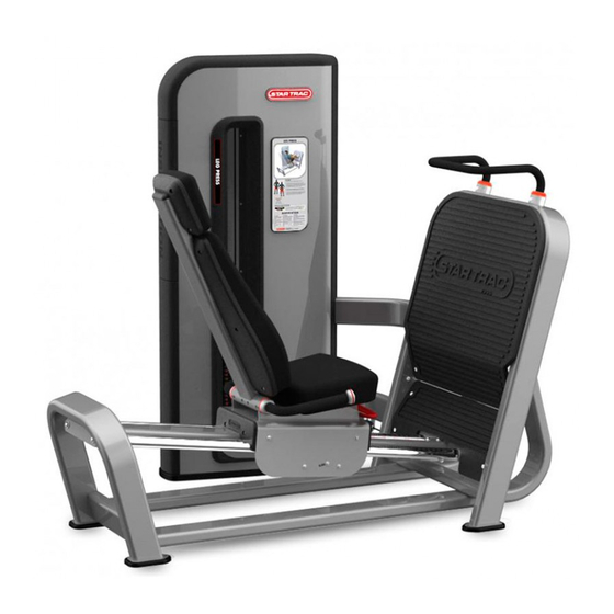
- Page 1 SEATED LEG PRESS IP-S1313 INSTALLATION INSTRUCTIONS...
- Page 2 Copyright 2009. Star Trac by Unisen, Inc. All rights reserved, including those to reproduce this book or parts thereof in any form without first obtaining written permission from Star Trac. Every effort has been made to keep this information current; however, periodically, changes are made to the information herein, and these changes will be incorporated into new editions of this publication.
-
Page 3: Installation Instructions
• All Star Trac Strength equipment MUST be secured to the floor using either 10mm or 3/8in. (grade 5 minimum) bolts. To accommodate this there are four mounting points inside the weight stack and one in either of the small feet. - Page 4 REMOVE SEAT FRAME FROM PALLET: Slide the SEAT FRAME forward at least 250mm (10 inches). Carefully rotate the SEAT FRAME down and off the pallet. CAUTION: SEAT FRAME weighs 100Kg (220 lbs) REMOVE THE SHROUDS: Using a 4MM hex key remove the (M6,30MM,Button Head Bolt) from the rear of the weight stack.
- Page 5 REMOVE FROM PALLET: With the shrouds removed, locate and remove the two bolts that secure the equipment to the pallet. There will also be a bolt through each of the equipment’s feet. Once all bolts fastening the equipment to the pallet have been removed, carefully remove equipment off of the pallet and place in desired location.
-
Page 6: Installing The Seat Assembly
RE-INSTALL MAIN FOOT PAD SUPPORT: Standoffs Align the MAIN FOOT PAD STANDOFFS with the back panel STANDOFFS and secure with (M8, 25MM, Socket Head Screws) recessed in the back panel using a 6MM hex key. INSTALLING THE SEAT ASSEMBLY: Place the SEAT ASSEMBLY onto the ROLLER GUIDE TUBES. -
Page 7: Main Frame Assembly
INSTALLING THE SEAT ASSEMBLY: Locate and connect the LINKAGE to the ROCKER ARM with the CLEVIS PIN. Then insert COTTER PIN as shown. Install the ROLLER GUIDE WHEEL using Linkage a (M8, 85MM, Button Head Screw), two (M8, Washer) and a (M8, Nyloc Nut). Note wheel orientation –... -
Page 8: Installing The Cable
PROTECTIVE FEET: Your equipment shipped with a set of PROTECTIVE FEET. Tilt the equipment towards the weight stack until the four smaller feet under the SEAT assembly lift off the ground; slip the PROTECTIVE FEET on and set the equipment back down. - Page 9 TOP PLATE & CABLE ADJUSTMENT: Engage pin at 1/3 to ½ maximum weight and lift weight stack 3 to 4 times to fully seat. Disengage pins and verify that there is no gap between the Top Plate and the lower weight plate. If a gap exists or if there is too much slack on the cable, then the cable tension needs to be adjusted.
- Page 10 INSTALLING THE SHROUDS: Insert the SHROUDS from the top sliding downward. The SHROUDS have seven hooks for mounting. Before the shroud can be slide down into place the SHROUD hooks need to be aligned with the corres- ponding mounting slots found on the weight frame of the equipment.
- Page 11 Page 11...
- Page 12 Page 12...
- Page 13 MACHINE CLEARANCE AND SPACING For the safe operation of Inspiration Strength™ Star Trac recommends that a clearance of 24 inches (60.96cm) be maintained between and behind machines including moving arms and levers. To insure safe entry and exit to each unit a walkway of at least 36 inches (91.44cm) inches is recommended front of, or on the entry side of each machine.
- Page 14 STAR TRAC 14410 Myford Road Irvine, California 92606 Telephone: (800) 228-6635, (714) 669-1660 Fax: (714) 508-3303 www.startrac.com Part No. 620-7927, Rev B., 21 Aug 09...