
Related Manuals for GE Concord 4 Series


Summary of Contents for GE Concord 4 Series
-
Page 1: Installation Instructions
466-2182 Rev. C GE Security September 2005 www.gesecurity.com Part Numbers: 600-1021-95R 600-1022-95R 600-1040 600-1042 Concord 4 Series Security Systems Installation Instructions WWW.DIYALARMFORUM.COM... - Page 2 4,855,713. Except expressly provided herein, the purchase of this product shall not constitute a license or otherwise provide a right to practice a method covered by any of the identified patents. GE Security hereby grants the purchaser of this product a limited, non-exclusive license to practice the methods patented in the identified patents solely with products manufactured, sold or licensed by GE Security.
-
Page 3: Table Of Contents
Contents About This Manual 1 About the User’s Guide ......................1 Special Installation Requirements .....................1 UL Listed Installations ......................1 Basic System ........................1 Household Burglary Alarm System Unit (UL 1023) ............1 Household Fire Warning System (UL 985) ................2 UL 1023 & 985 24-Hour Backup ..................2 SIA System Requirements .....................2 SIA Setting Requirements ....................2 Commercial Burglary Alarm System Unit (Grade B UL 1610) .........3... - Page 4 Connecting Exterior/Interior Piezo Sirens ................14 Output 1 ..........................14 Piezo Dynamic Exterior Siren (13-950) ................14 Output 2 ..........................15 Hardwire Interior Siren (13-949) ..................15 Connecting an Interrogator 200 Audio Verification Module (60-677) ........15 Connecting SuperBus 2000 Touchpads ................... 16 Installing SuperBus 2000 Modules ..................
- Page 5 Siren Options Menu ......................50 Sensors Menu ........................51 Audio Verification Menu ......................54 Accessory Modules Menu ....................56 Onboard Options Menu ......................59 Smoke Verify (1100) ......................60 Macro Keys Menu ........................61 Exiting Programming Mode ....................62 Entering Quick Programming Mode ..................62 Entering User Programming Mode ..................62 Time and Date Menu ......................63 User Codes Menu .........................63 Options Menu ........................65...
-
Page 6: About This Manual
145-CN (order #600-1023-CN), or Power Line Carrier Class II 16.5 VAC, 40 VA power transformer 22-149 (order #600-1024) or 22-149-CN (order #600-1024-CN). These trans- formers must be ordered separately from GE Security. • Backup Battery 12V 4.5 Ah (60-681) or 12V 7 AH (60-680) ®... -
Page 7: Household Fire Warning System (Ul 985)
0311 - 0361 Exit Delay 60 sec. 45-184 sec. 06015 Swinger Limit 1100 Smoke Verify On if smoke alarms are programmed into system Cross Zoning Disabled Enabled for zones with a high probability of false alarms WWW.DIYALARMFORUM.COM Concord 4 Series Systems... -
Page 8: Commercial Burglary Alarm System Unit (Grade B Ul 1610)
AC Failure set to on Entry Delay plus Dialer Abort Delay must not • Phone Number must be programmed exceed 60 seconds. • Low CPU Battery set to on • Next Phone Test set to 1 WWW.DIYALARMFORUM.COM Concord 4 Series Systems... -
Page 9: Central Station Reporting
Power: Input for an AC step-down, plug-in style transformer. • Auxiliary Power Output: Output that supplies 9 to 14 VDC with up to 1 amp for bus devices and hardwired detectors, such as smoke and motion detectors. WWW.DIYALARMFORUM.COM Concord 4 Series Systems... -
Page 10: Superbus 2000 Touchpads
SuperBus 2000 Phone Interface/Voice Module This module allows system access and control using touch-tone telephones, on- or off-site. The module includes an output for a speaker that sounds system status and alarm voice messages. WWW.DIYALARMFORUM.COM Concord 4 Series Systems... -
Page 11: Snapcards
Identifying Panel Main Components • Installing Optional SnapCards • Connecting Detection Devices to Panel Zone Inputs • Connecting Speakers • Connecting Piezo Sirens • Connecting an Interrogator 200 Audio Verification Module • Connecting Alphanumeric and Fixed Display Touchpads WWW.DIYALARMFORUM.COM Concord 4 Series Systems... -
Page 12: Determine The Panel Location
7.0 Ah battery. Wire Length The total system wire length allowed can vary depending on devices powered by the panel, the wire length between devices and the panel, and the combined wire length of all devices. WWW.DIYALARMFORUM.COM Concord 4 Series Systems... - Page 13 120 µA 80 mA 18 ga.—330 ft. 22 ga.—750 ft. Hardwire Interior Siren (13-949) 0 mA 85 mA 18 ga.—1,500 ft. 22 ga.—750 ft. Piezo Dynamic Exterior Siren (13-950) 0 mA 150 mA 18 ga.—1,500 ft. WWW.DIYALARMFORUM.COM Concord 4 Series Systems...
-
Page 14: Mounting The Panel
Level the panel and mark the top and bottom mounting holes. Install anchors where studs are not present. Partially insert screws into the two top mounting hole locations, then hang the panel on the two screws. WWW.DIYALARMFORUM.COM Concord 4 Series Systems... -
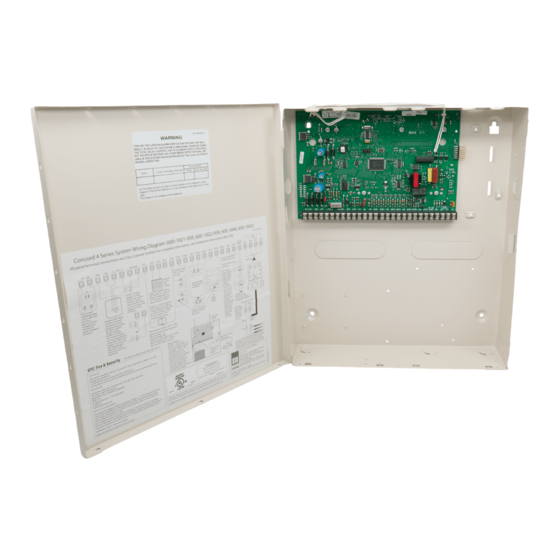
Page 15: Identify Panel Components
Install a plastic antenna shroud (included with panel) over each antenna and snap them into the Note Skip this step for Concord 4 holes on top of the enclosure (see Figure 4). Hybrid and Concord 4 com- mercial systems. Figure 4. Installing Antenna Shrouds WWW.DIYALARMFORUM.COM Concord 4 Series Systems... -
Page 16: Connecting The Panel To Earth Ground
When using 2-wire smoke detectors on zone 8, the Two-Wire Smoke setting (in program mode) must be turned on before entering the menu. See — in the section LEARN SENSORS ONBOARD OPTIONS INPUTS “Programming the Panel” for complete details. WWW.DIYALARMFORUM.COM Concord 4 Series Systems... -
Page 17: Connecting 2-Wire Smoke Detectors
..+ - - 2k Ohm EOL 2k Ohm EOL Resistor 49-454 (Locate at Last Detector) Resistor 49-454 (Locate at Last Detector) Figure 8. Connecting 2 and 4-Wire Smoke Detectors to the Panel WWW.DIYALARMFORUM.COM Concord 4 Series Systems... -
Page 18: Connecting 4-Wire Smoke Detectors
For exterior siren applications, connect the speaker to the panel using 18-gauge wire as shown in piezo siren to the speaker Figure 9. output (terminals 7 and 8). Speaker Speaker Splice 2 8-Ohm Speakers in Series (16 Ohms) Figure 9. Connecting Exterior Speakers to the Panel WWW.DIYALARMFORUM.COM Concord 4 Series Systems... -
Page 19: Hardwire Interior Speaker (60-528)
This siren is not UL approved for use as an outdoor sounding device. Connect the siren to panel as shown in Figure 11. O U T 1 G N D Panel Terminals Black Figure 11. Connecting Exterior Sirens WWW.DIYALARMFORUM.COM Concord 4 Series Systems... -
Page 20: Output 2
Caution Yellow Splice Microphone Cable Speaker Cable M I C G N D + 1 2 V S P E A K E R Panel Terminals Cable Shield Figure 13. Connecting an Interrogator 200 AVM WWW.DIYALARMFORUM.COM Concord 4 Series Systems... -
Page 21: Connecting Superbus 2000 Touchpads
Mounting Side Clips (6) Mounting Clip Screws Support Standoffs Figure 15. Installing SuperBus 2000 Modules WWW.DIYALARMFORUM.COM Concord 4 Series Systems... -
Page 22: Superbus 2000 2 Amp Power Supply (600-1019)
SuperBus 2000 Voice Only Module The module can be mounted inside or outside of the control panel cabinet. Refer to the SuperBus 2000 Voice Only Module Installation Instructions included with each module, for complete mounting instructions. WWW.DIYALARMFORUM.COM Concord 4 Series Systems... -
Page 23: Superbus 2000 Phone Interface/Voice Module (60-777-01)
Figure 20. When connected as shown, the speaker only produces status voice messages. outside, do not connect In an alarm, the speaker announces voice status messages. exterior speakers to Phone Interface/Voice module ter- minals 6 and 7. WWW.DIYALARMFORUM.COM Concord 4 Series Systems... -
Page 24: Wiring For Status And Alarm Messages
Connect the SuperBus 2000 8Z Input Module to the panel as shown in Figure 22. Connect all necessary input wiring using the Installation Instructions included with the module. SuperBus 2000 4-Relay Output Module (60-770) Connect the SuperBus 2000 4-Relay Output Module to the panel as shown in Figure 22. WWW.DIYALARMFORUM.COM Concord 4 Series Systems... -
Page 25: Superbus 2000 Cellular Backup Module
+ 1 2 V B U S A B U S B G N D G N D Z O N E G N D O U T Figure 23. Wiring the Cellular Backup Module to the Panel WWW.DIYALARMFORUM.COM Concord 4 Series Systems... -
Page 26: Superbus 2000 Automation Module (60-783-02)
At the TELCO protector block, remove the premises phone lines from the block and splice off-site phones. them to the black and white (or yellow) wires of the 4-conductor cable (see C in Figure 26). WWW.DIYALARMFORUM.COM Concord 4 Series Systems... -
Page 27: Connecting The Phone Line To The Panel With A Db-8 Cord
Do not plug in the power transformer or connect the backup battery at this time. The panel must be powered up using the sequence of steps described in the next section, “Powering Up the Panel.” Caution WWW.DIYALARMFORUM.COM Concord 4 Series Systems... -
Page 28: Powering Up The Panel
Press 8 + 4321 + 0 + 2. The touchpad sounds one short beep. Press * and verify that the dis- play shows SERVICE TOUCHPAD ACTIVE Press 8 + 4321 + 0 + 0 and the display shows SYSTEM PROGRAMMING WWW.DIYALARMFORUM.COM Concord 4 Series Systems... -
Page 29: Touchpad Button Programming Functions
Tier 2 Menus SYSTEM PRO- PHONE SECURITY PHONES TIMERS GRAMMING OPTIONS LIGHT TOUCHPAD SIREN REPORTING CONTROL OPTIONS OPTIONS AUDIO ACCESSORY ONBOARD SENSORS VERIFICATION MODULES OPTIONS MACRO KEYS Figure 29. Tier 1 and Tier 2 Program Menus WWW.DIYALARMFORUM.COM Concord 4 Series Systems... -
Page 30: Programming Tier 1 Menu Items
To Copy Partition 1: With the display showing , press # + installer CODE + #. The display PARTITION 1 COPY flashes, then stops after pressing # and shows DONE WWW.DIYALARMFORUM.COM Concord 4 Series Systems... -
Page 31: Clear Memory (System Programming)
The Downloader Code will be reset to defaults during a Memory Clear only if the Dealer Code is not set OR if the Dealer Code is used to initiate the Memory Clear. Note Downloader programming has not been investigated by UL. WWW.DIYALARMFORUM.COM Concord 4 Series Systems... -
Page 32: Partition Security (0004)
7 + 4 + PTN n (n = 1-6). The display flashes the entered setting. Note 2. Press # and the display shows the new Regardless of the setting, an access code can always be used to jump partitions. setting. WWW.DIYALARMFORUM.COM Concord 4 Series Systems... -
Page 33: Multi-Partition Arm/Disarm (0005)
When disarming multiple partitions, any partitions in alarm have the affected partition number flashing on touchpad displays. Pressing # can- cels all alarms in the selected partitions. Alarm memory information is then displayed for all canceled alarms. WWW.DIYALARMFORUM.COM Concord 4 Series Systems... -
Page 34: Keychain Tp Ptn (0006)
Alpha characters A–F can be assigned to the account number by pressing Press # and the display shows the new and holding buttons 1–6 respectively, until the character appears. number. Note When using the CID reporting format, the letter “A” is reported as a “0”. WWW.DIYALARMFORUM.COM Concord 4 Series Systems... -
Page 35: Exit Extension (0013 - 0063)
The system can be armed only after the siren timeout expires.Keyswitch sensors test the same as any other sensor and do not arm or disarm the system during a sensor test. WWW.DIYALARMFORUM.COM Concord 4 Series Systems... -
Page 36: Duress Code (0016 - 0066)
To program a dialing prefix that disables call-waiting, see NUMBER PHONE OPTIONS—GLOBAL the Call Wait Cancel setting under the menu The display shows HONE NUMBER _ For UL 1610 & 1635 installations, a phone number must be programmed. WWW.DIYALARMFORUM.COM Concord 4 Series Systems... - Page 37 (on). The display flashes the entered setting. Note Press # and the display shows the new set- To use this feature, the Opening Reports and Closing Reports settings under ting. REPORTING menu must be turned on for that partition. WWW.DIYALARMFORUM.COM Concord 4 Series Systems...
- Page 38 With the display showing PHONE NUMBER To enter *, press and hold 7 for about two seconds. (current number), press D. The display shows To enter #, press and hold 9 for about two seconds. PHONE NUMBER _ WWW.DIYALARMFORUM.COM Concord 4 Series Systems...
- Page 39 With the display showing LATCHKEY RPTS (current setting), press 1 (off) or 2 OFF/ON (on). The display flashes the entered setting. Press # and the display shows the new setting. WWW.DIYALARMFORUM.COM Concord 4 Series Systems...
-
Page 40: Phone Options Menu
(current setting), press 1 (off) or 2 (on). The display flashes the entered setting. Note Press # and the display shows the new setting. For UL 1610 & 1635 listed installations, this feature must be set to on. WWW.DIYALARMFORUM.COM Concord 4 Series Systems... -
Page 41: Dialer Abort Delay (02006)
(15–45). The display flashes the entered set- For UL Listed systems, the combined time for the Entry Delay and Dialer ting. Abort Delay must not exceed 60 seconds. Press # and the display shows the new setting. WWW.DIYALARMFORUM.COM Concord 4 Series Systems... -
Page 42: Cancel Message (02007)
The following sections describe the Phone Options settings that appear under PARTITION 1-6 A Phone Interface/Voice Module must be installed for the system to use the settings under PHONE OPTIONS— PARTITION 1-6 (except Line Fail Delay) WWW.DIYALARMFORUM.COM Concord 4 Series Systems... - Page 43 With the desired partition selected, press A or B until the dis- trouble or alarm condition exists. play shows (current setting). TOLL SAVER OFF/ON 1 (off) or 2 (on). The display flashes the entered setting. Press # and the display shows the new setting. Press WWW.DIYALARMFORUM.COM Concord 4 Series Systems...
-
Page 44: Timers Menu
Press # and the display shows the new For UL 985, 1610 & 1635 listed installations, the RF Tx Timeout must be set to 4 hours. For UL 1023 listed installations, the RF Tx Timeout must be set to 24 hours. setting. WWW.DIYALARMFORUM.COM Concord 4 Series Systems... - Page 45 To turn Daylight Saving off or on: saving time changes. With the display showing DAYLIGHT SAVING (current setting), press 1 (off) or 2 OFF/ON (on). The display flashes the entered setting. Press # and the display shows the new setting. WWW.DIYALARMFORUM.COM Concord 4 Series Systems...
-
Page 46: Entry Delay (0310 - 0360)
Press # and the display show the new setting. Note To turn off Sleep Time: For UL listed installations, this feature must be set to off. With the display showing (cur- SLEEP TIME hh:mm rent setting), press D. WWW.DIYALARMFORUM.COM Concord 4 Series Systems... -
Page 47: Light Control Menu
Press # and the dis- letter that appears automatically after the house code number indicates play shows the new house code. the necessary HOUSE dial setting for X10 modules in that partition. WWW.DIYALARMFORUM.COM Concord 4 Series Systems... -
Page 48: Touchpad Options Menu
(current setting), press 1 (off) or 2 (on). The display When this setting is off, each key-press increments the arming level flashes the entered setting. (i.e., from OFF to STAY, from STAY to AWAY). Press # and the display shows the new setting. WWW.DIYALARMFORUM.COM Concord 4 Series Systems... -
Page 49: Reporting Menu
(memory) of the panel. When this setting is off, all system (current setting), press 1 (off) or 2 (on). The display events are logged in the buffer. flashes the entered setting. Press # and the display shows the new setting. WWW.DIYALARMFORUM.COM Concord 4 Series Systems... - Page 50 (current setting), press 1 (off) or 2 (on). The display flashes the entered setting. Note Press # and the display shows the new setting. As with all GE Security panels, hardwire smoke detectors connected to panel or SnapCard hardwire zones do not send restorals. WWW.DIYALARMFORUM.COM Concord 4 Series Systems...
- Page 51 RF LOW BAT RPT DAILY/ device is reporting a low battery condition to the panel. (current setting), press 1 (daily) or 2 WEEKLY (weekly). The display flashes the entered setting. Press # and the display shows the new setting. WWW.DIYALARMFORUM.COM Concord 4 Series Systems...
-
Page 52: Swinger Limit (06015)
The display flashes the entered setting. To use this feature, the Open/Close Reports settings under the PHONES menu must be turned on for the specific CS Phone or Pager number. Press # and the display shows the new setting. WWW.DIYALARMFORUM.COM Concord 4 Series Systems... - Page 53 This causes the system to automatically bypass the open (protesting) sensors. Auto-forced arming always reports to the central monitoring station. Auto-forced arming has not been investigated by UL. WWW.DIYALARMFORUM.COM Concord 4 Series Systems...
-
Page 54: Alarm Verify (06108 - 06608)
Press # and the display shows the new setting. Verify is set to on, group 18 responds the same as group 17 (see “Appendix B, Table B1 “Sensor Group Characteristics”). Note For UL Listed installations, Alarm Verify must be set to off. WWW.DIYALARMFORUM.COM Concord 4 Series Systems... -
Page 55: Siren Options Menu
Press # and the display shows the new setting. If Immediate Beeps is set to on, trouble beeps sound for supervisory trou- ble conditions regardless of this menu setting. Note For UL Listed installations, Disable Trouble Beeps must be set to off. WWW.DIYALARMFORUM.COM Concord 4 Series Systems... -
Page 56: Sensors Menu
A normally closed door, for example, should be Hardwire Zones closed when you begin the Learn Sensors process. To trip the zone, open the door. Wireless Sensors Follow the instructions included with each sensor. WWW.DIYALARMFORUM.COM Concord 4 Series Systems... - Page 57 1 ( LEARN SENSORS Table 7: Onboard Hardwire Zone Factory Programming Zone Input Group No. & Description 10–Entry/Exit 17–Instant Interior Follower 13–Instant Perimeter 13–Instant Perimeter 13–Instant Perimeter 13–Instant Perimeter WWW.DIYALARMFORUM.COM Concord 4 Series Systems...
- Page 58 Press A or B and the display shows (current group SENSOR GROUP nn Other description codes include, = wireless assignment). sensor, = touchpad, = normally open. Enter the desired group number, then press #. The display shows the new group assignment. WWW.DIYALARMFORUM.COM Concord 4 Series Systems...
-
Page 59: Audio Verification Menu
(off) during a silent or duress alarm the display shows (current setting). SILENT TALKBACK OFF/ON audio session. 1 (off) or 2 (on). The display flashes the entered setting. Press # Press and the display shows the new setting. WWW.DIYALARMFORUM.COM Concord 4 Series Systems... - Page 60 Enter the desired 2-digit setting (01 - 64). The display flashes the results, this setting should be higher than the Vox entered setting. Press # and the display shows the new setting. Mic Gain. Manual Mic Gain (09009) Audio Verification-Partition 1 (Default = 64) Not used. WWW.DIYALARMFORUM.COM Concord 4 Series Systems...
-
Page 61: Accessory Modules Menu
Exit programming mode. Remove AC and battery power from the panel. Replace the defective bus device with a new one. Apply AC and battery power to the panel. WWW.DIYALARMFORUM.COM Concord 4 Series Systems... -
Page 62: Output Programming
(current setting). BEEPS OFF/ON sons. Press 1 (off) or 2 (on) to select the desired setting. The dis- play flashes the entered selection. Press # and the display shows the new setting. WWW.DIYALARMFORUM.COM Concord 4 Series Systems... - Page 63 ZIP (B) or 2 (A). The display flashes the entered selection. code. Press # and the display shows the new setting. The following describes how to program the settings that appear under SNAPCARDS. WWW.DIYALARMFORUM.COM Concord 4 Series Systems...
-
Page 64: Onboard Options Menu
—This menu lets you set configuration numbers for the two built- OUTPUT PROGRAMMING in panel outputs and assign the outputs to partitions. • —This menu lets you assign text to the two built-in outputs so they can be OUTPUT TEXT controlled by the user. WWW.DIYALARMFORUM.COM Concord 4 Series Systems... -
Page 65: Smoke Verify (1100)
Press # and repeat steps 2 through 6 until all outputs are pro- put Text is programmed, user Output Control will not function for that output. grammed. Use the system event trigger and response numbers listed in Appendix B: Reference Tables. WWW.DIYALARMFORUM.COM Concord 4 Series Systems... -
Page 66: Macro Keys Menu
When using an ATP2100 or ATP2600 to jump to another partition, pressing the entered command. The display the macro buttons on the “jumped” touchpad will execute macro commands stops flashing. based on the macros programmed in the jumped partition. WWW.DIYALARMFORUM.COM Concord 4 Series Systems... -
Page 67: Exiting Programming Mode
You can enter user programming from an alphanumeric or fixed display touchpad by using the system or partition master code. The default system master code is 1234. To enter user-programming mode: Press 9 + CODE. The display shows TIME AND DATE WWW.DIYALARMFORUM.COM Concord 4 Series Systems... -
Page 68: Time And Date Menu
#. The display shows nnn - nnnn. USER Enter the system or partition master code. The display flashes the entered code. Press # and the display shows nnn -- (no code). USER **** WWW.DIYALARMFORUM.COM Concord 4 Series Systems... -
Page 69: Direct Bypassing
- nnnn Press A or B until the display shows (current setting). LATCHKEY OFF/ON Press 1 (off) or 2 (on). The display flashes the entered setting. Press # and the display shows the new setting. WWW.DIYALARMFORUM.COM Concord 4 Series Systems... -
Page 70: Options Menu
For this feature to work, the panel must be connected to a phone line and be programmed with REMOTE ACCESS on, with a Downloader # and the display shows the new setting. selection. Press phone number, and with a Downloader code. WWW.DIYALARMFORUM.COM Concord 4 Series Systems... -
Page 71: Set Up Schedules Menu
If you use the same start and stop times described above and set the schedule to turn on Monday through Friday, then one schedule will cover the entire week. WWW.DIYALARMFORUM.COM Concord 4 Series Systems... -
Page 72: Attach Schedules To Events Menu
A or B until the desired schedule appears. Press 1 (off) or 2 (on). The display flashes the entered selection. Press # and the display shows the new setting for the selected schedule. WWW.DIYALARMFORUM.COM Concord 4 Series Systems... - Page 73 Press 1 (off) or 2 (on). The display flashes the entered selection. Press # and the display shows the new setting for the selected schedule. Repeat steps 4 and 5 until all desired schedules are attached. WWW.DIYALARMFORUM.COM Concord 4 Series Systems...
-
Page 74: Energy Saver Menu
To detach a light from a sensor: With the display showing (current setting), press A or LIGHT 1 TO SENSOR y B to select the desired light number. Enter 0 as the sensor number and press #. WWW.DIYALARMFORUM.COM Concord 4 Series Systems... -
Page 75: System Version Menu
You should test the system after installing or servicing and after adding or removing devices from working environment. the system. Refer to the “Troubleshooting” section if correct test results are not achieved. WWW.DIYALARMFORUM.COM Concord 4 Series Systems... -
Page 76: Basic System Commands
8 + installer CODE + 3 while the sys- less Sensor Does Not Test.” tem is still in sensor test mode. This restarts the 15 minutes of test time. WWW.DIYALARMFORUM.COM Concord 4 Series Systems... -
Page 77: If A Wireless Sensor Does Not Test
002 = sensor/zone in alarm or user number, 7468 = last four digits of account number. When you finish testing the system, call the central monitoring station to verify that the alarms were received. Table 9 describes pager system event codes. WWW.DIYALARMFORUM.COM Concord 4 Series Systems... -
Page 78: Testing Outputs And Sirens
Table 11 describes the system alarm sounds you should hear for each alarm event. Contact the central monitoring station when you are finished testing. Table 11: System Alarm Sounds Alarm Type Alarm Sound Fire Repeating series of three beeps Police/Intrusion Continuous tone Auxiliary Rapid beeps WWW.DIYALARMFORUM.COM Concord 4 Series Systems... -
Page 79: Testing Light Control
You will need a helper and touch-tone phone at an off-site location to perform this test. When testing the AVM from off-site the following guidelines must be followed. • The Remote Access feature must be set to on (default). WWW.DIYALARMFORUM.COM Concord 4 Series Systems... -
Page 80: Testing Cellular Backup Communication
Verify the CS report. If success does not occur, verify that the signal strength (RSSI) shown on the Cellular Backup Module is acceptable and repeat steps 5-8. 10. Restore previous CS PHONE 1 settings if needed. WWW.DIYALARMFORUM.COM Concord 4 Series Systems... -
Page 81: Troubleshooting
Check your records to see if you have the customer’s access code(s) on file. Verify the access code(s) using the Downloader. Clear memory and reprogram the panel locally. Clearing the memory will erase onboard hardwire zone factory programming. Installer cannot remember install code. WWW.DIYALARMFORUM.COM Concord 4 Series Systems... - Page 82 10. For pagers, extend the pager delay setting (see the PHONE OPTIONS—GLOBAL menu in the “Programming” section. Alphanumeric Touchpads Display shows all ************. Touchpad is not connected to panel bus terminals or is wired incorrectly. Check and correct wiring. Display is blank. WWW.DIYALARMFORUM.COM Concord 4 Series Systems...
- Page 83 Check for zone wire fault—short circuit on N/C loops, open circuit on N/O loops. Make sure all devices on zone are in non-alarm state, then enter disarm command to reset zone. Wireless Sensor Zones System doesn’t respond (in sensor test or when armed) when sensor is tripped. WWW.DIYALARMFORUM.COM Concord 4 Series Systems...
- Page 84 Constant dial tone, preventing dial-out on premises phones. One or more polarity-sensitive phones exist on-site. Reverse the phone wires connected to the brown and gray wire terminals on the RJ-31X jack. Light Control Light controlled by X10 Lamp Module is not working. WWW.DIYALARMFORUM.COM Concord 4 Series Systems...
- Page 85 Check that the Cellular Backup Module has been activated as outlined in the device Installation Instructions. The panel indicates “auxiliary phone trouble 2.” Check the antenna connection. Adjust the antenna positioning for maximum signal. Verify Cellular System setting. The panel indicates “auxiliary phone trouble 3.” WWW.DIYALARMFORUM.COM Concord 4 Series Systems...
- Page 86 Access code Lock feature must be turned off to work properly. Module doesn’t communicate with alarm.com. Check module’s status LED’s. Refer to the “SuperBus 2000 Wireless Gateway Module” instruc- tions for a description of the LED’s. WWW.DIYALARMFORUM.COM Concord 4 Series Systems...
-
Page 87: Appendix A: System Planning Worksheets
60-703-95 Crystal Indoor PIR Motion Sensor Adjustable Dual technology Sound 60-834-95R Sensor 60-597 HiTech Handheld Wireless Touchpad 60-607* 2-Button Keychain Touchpad 60-606* 4-Button Keychain Touchpad 60-659-95R* SAW 4-Button Keychain Touchpad 60-832-95R* 2-Button ELM Keychain Touchpad WWW.DIYALARMFORUM.COM Concord 4 Series Systems... -
Page 88: Hardwire Devices Table
Total current only for all 2-wire smoke detectors connected to panel 2-wire smoke loop. †† Note When installing SuperBus 2000 RF Receiver Modules, the Antenna Tamper feature must be set to off (see REPORTING—GLOBAL in the “Programming” section). WWW.DIYALARMFORUM.COM Concord 4 Series Systems... - Page 89 Table A3: Zone and Sensor Assignments Module Bus Module Input RF Zone Group Partition Zone/Sensor Text ID Number Number WWW.DIYALARMFORUM.COM Concord 4 Series Systems...
- Page 90 Table A3: Zone and Sensor Assignments (Continued) Module Bus Module Input RF Zone Group Partition Zone/Sensor Text ID Number Number WWW.DIYALARMFORUM.COM Concord 4 Series Systems...
- Page 91 Cellular Backup CS Phone 1 On, CS Phone 2-3 Off 1_____________2_____________3___________ 01027 Cellular System B Closing Reports Off 06101 - 06601 Comm. Failure On 02003 01000, 01010, CS Phone 1-3 None 1_____________2_____________3___________ 01020 Daylight Saving On 0307 WWW.DIYALARMFORUM.COM Concord 4 Series Systems...
- Page 92 Keyswitch Style Transition 0015-0065 Latchkey Format Off 06105-06605 01035, 01045, 1_____________2_____________3___________ Latchkey Reports (pagers) On 01055, 01065, 4_____________5_____________ 01075 Latchkey Zones None 0500 Learn Sensors None Line Fail Delay None 0213 Local Phone Control On 0210-0260 WWW.DIYALARMFORUM.COM Concord 4 Series Systems...
- Page 93 Ring/Hang/Ring On 0212-0262 01006, 01016, Reporting Format (SIA/CID) CID 1_____________2_____________3___________ 01026 Sensor Text None Silent Talkback Off 09003 Siren Timeout 4 min 0313-0363 Siren Verify Off 0710 Sleep Time Off 0314-0364 Smoke Verify Off 1100 WWW.DIYALARMFORUM.COM Concord 4 Series Systems...
- Page 94 TP Panic RPT FMT Off 06010 Two Trip Error Off 06009 Two Wire Smoke Off 1101 UL 98 Options Off 0702 VOX Gain Range 09008 VOX Mic Gain 09007 VOX RX Gain 09010 Zone Restorals Off 06008 WWW.DIYALARMFORUM.COM Concord 4 Series Systems...
-
Page 95: Appendix B: Reference Tables
Auxiliary opens and closes. Sirens shut off at restoral. * Local Special Notify the user when a door is opened. Sounds emit Special √ Instant 1, 2, 3 Chime from a local annunciator. * Chime WWW.DIYALARMFORUM.COM Concord 4 Series Systems... -
Page 96: Cross-Zoning
M o t i o n S e n s o r M o t i o n S e n s o r P a t h o f P e r s o n W a l k i n g WWW.DIYALARMFORUM.COM Concord 4 Series Systems... - Page 97 Carbon First Main Safe Monoxide Central Floor Master Schedule Chime Force Screen Closed Foyer Medical Second Closet Freeze Memory Sensor Closing Front Menu Service Code Furnace Mother’s Shed Computer Gallery Motion Shock Control Garage Side WWW.DIYALARMFORUM.COM Concord 4 Series Systems...
- Page 98 When any sensor in group XX goes into alarm Table B4 Sensor XX in Alarm When sensor number XX goes into alarm Table B5 Sensor XX Open When sensor number XX is opened Table B5 WWW.DIYALARMFORUM.COM Concord 4 Series Systems...
- Page 99 Sensor 13 in alarm open Sensor 14 in alarm open Sensor 15 in alarm open Sensor 16 in alarm open Sensor 17 in alarm open Sensor 18 in alarm open Sensor 19 in alarm open WWW.DIYALARMFORUM.COM Concord 4 Series Systems...
- Page 100 Sensor 55 in alarm open Sensor 56 in alarm open Sensor 57 in alarm open Sensor 58 in alarm open Sensor 59 in alarm open Sensor 60 in alarm open Sensor 61 in alarm open WWW.DIYALARMFORUM.COM Concord 4 Series Systems...
- Page 101 Sensor 90 in alarm open Sensor 91 in alarm open Sensor 92 in alarm open Sensor 93 in alarm open Sensor 94 in alarm open Sensor 95 in alarm open Sensor 96 in alarm open WWW.DIYALARMFORUM.COM Concord 4 Series Systems...
- Page 102 The point will activate and deactivate according to the current alarm type: Siren pattern Auxiliary -- fast on/off/on Police -- constant on Fire -- repeating Trip delay The point will activate 30 seconds after the trigger event occurs WWW.DIYALARMFORUM.COM Concord 4 Series Systems...
-
Page 103: Notes For Table B8: Response Numbers
To deactivate the output before the 3-minute time expires, you must enter program for 30 seconds and cannot mode or remove panel power. be changed. Activated outputs set up for a momentary or 3-minute response time restart if the same trig- ger event occurs again. WWW.DIYALARMFORUM.COM Concord 4 Series Systems... -
Page 104: Appendix C: Settings
Reporting Format Reporting Format * * * * SIA CID SIA CID SIA CID (0006) (0016 - 0066) (01006) (01016) (01026) Cellular Backup Cellular Backup Cellular Backup On Off On Off On Off (01007) (01017) (01027) WWW.DIYALARMFORUM.COM Concord 4 Series Systems... - Page 105 1 2 3 4 5 6 1 2 3 4 5 6 1 2 3 4 5 6 1 2 3 4 5 6 1 2 3 4 5 6 (01037) (01047) (01057) (01067) (01077) WWW.DIYALARMFORUM.COM Concord 4 Series Systems...
- Page 106 (0315 - 0365) Cancel Message Phone ACC Key Daylight Saving On Off On Off (02007) (0307) (0216 - 0266) Pager Delay 15 sec (0-30) (02008) Call Wait Cancel On Off (02009) Dial Tone Detect On Off (02010) WWW.DIYALARMFORUM.COM Concord 4 Series Systems...
- Page 107 (06011) Receiver Failure Ground Fault On Off On Off (06012) (06017) RF Low Bat Rpt RF Supv Rpt Swinger Limit Aux Power Fail Daily Weekly Daily Weekly 1 (1-2) On Off (06013) (06014) (06015) (06016) WWW.DIYALARMFORUM.COM Concord 4 Series Systems...
- Page 108 Sensor n Item 0 Sensor Partition Disable Trbl Beeps Sensor Group Delete Sensor n On Off Done (0701) UL 98 Options Trip Sensor Sensor Group On Off (0702) Global Fire On Off (0703) Silent Panic On Off (0704) WWW.DIYALARMFORUM.COM Concord 4 Series Systems...
- Page 109 * * * * OPTIONS (09006) VOX Mic Gain 14 (01-64) (09007) VOX Gain Range 64 (01-64) (09008) Manual Mic Gain 04 (cannot change) (09009) VOX RX Gain 08 (01-10) (09010) ACCESSORY MODULES (cont.) SNAPCARDS WWW.DIYALARMFORUM.COM Concord 4 Series Systems...
- Page 110 Partition Assign Partition Assign Output 1 Output 2 On Off 1 2 3 4 5 6 1 2 3 4 5 6 Item n Item n (1101 (11100) (11110) Configuration Configuration 01614 01710 (11101) (11111) WWW.DIYALARMFORUM.COM Concord 4 Series Systems...
-
Page 111: Appendix D: Software Release Notes
Maximum Humidity: ..85% Relative Humidity (non-condensing) Auxiliary Power Output: 1.0 A @ 9 to 14 VDC (12 VDC typical) Dimensions: .....14 in. (35.6 cm) x 12 in. (30.5 cm) x 3.0 in. (7.6 cm) (H x W x D) WWW.DIYALARMFORUM.COM Concord 4 Series Systems... -
Page 112: System Wiring Notes
Use 60-681—12 VDC, 4.5 Ah or 60-680—12 VDC, 7 Ah backup battery. Battery is auto- matically tested every 24 hours (every 4 hours with UL 98 Options set to on). Replace only with exact replacement. Without AC power, panel shutdown occurs if battery voltage falls below 10.2 VDC. WWW.DIYALARMFORUM.COM Concord 4 Series Systems... - Page 113 Z O N E 8 Z O N E C O M M O N Z O N E 7 Z O N E 6 Z O N E C O M M O N Z O N E 5 Z O N E 4 Z O N E C O M M O N Z O N E 3...