Advertisement
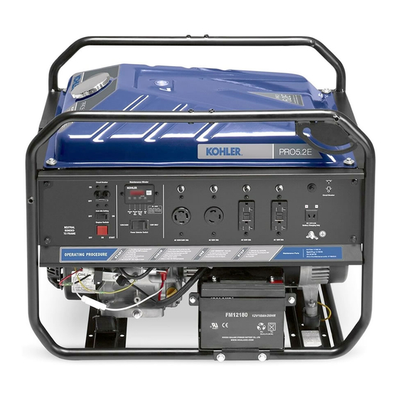
PRO 5.2, PRO 5.2 E, PRO 7.5, PRO 7.5 E
Generator Service Manual
IMPORTANT:
Read all safety precautions and instructions carefully before operating equipment. Refer to operating
instruction of equipment that this engine powers.
Ensure engine is stopped and level before performing any maintenance or service.
For all engine related maintenance, disassembly and reassembly, refer to service manual of engine
powering this equipment.
2
Safety
3
Specifi cations
6
Troubleshooting
9
Electrical System
14
Disassembly/Inspection and Service
16
Reassembly
37 690 01 Rev. --
KohlerPower.com
1
Advertisement
Table of Contents

Related Manuals for Kohler PRO 5.2


Summary of Contents for Kohler PRO 5.2
- Page 1 PRO 5.2, PRO 5.2 E, PRO 7.5, PRO 7.5 E Generator Service Manual IMPORTANT: Read all safety precautions and instructions carefully before operating equipment. Refer to operating instruction of equipment that this engine powers. Ensure engine is stopped and level before performing any maintenance or service.
-
Page 2: Safety Precautions
Safety SAFETY PRECAUTIONS WARNING: A hazard that could result in death, serious injury, or substantial property damage. CAUTION: A hazard that could result in minor personal injury or property damage. NOTE: is used to notify people of important installation, operation, or maintenance information. CAUTION WARNING WARNING... -
Page 3: Specifications
Specifi cations ENGINE IDENTIFICATION NUMBERS Kohler engine identifi cation numbers (model, specifi cation and serial) should be referenced for effi cient repair, ordering correct parts, and engine replacement. Model ..... -
Page 4: Torque Specifications
Specifi cations TORQUE SPECIFICATIONS Alternator Front Cover 53.5 N·m (474 in. lb.) Alternator Rear Cover 4.5 N·m (40 in. lb.) AVR and Brush Assembly 4.0 N·m (35 in. lb.) Battery Mounting Bracket M6 Screws 9.9 N·m (87 in. lb.) M8 Screws 25.0 N·m (221 in. -
Page 5: General Torque Values
Specifi cations GENERAL TORQUE VALUES English Fastener Torque Recommendations for Standard Applications Bolts, Screws, Nuts and Fasteners Assembled Into Cast Iron or Steel Grade 2 or 5 Fasteners Into Aluminum Size Grade 2 Grade 5 Grade 8 Tightening Torque: N·m (in. lb.) ± 20% 8-32 2.3 (20) 2.8 (25) -
Page 6: Troubleshooting Guide
Troubleshooting TROUBLESHOOTING GUIDE When troubles occur, be sure to check simple causes which, at fi rst, may seem too obvious to be considered. For example, a starting problem could be caused by an empty fuel tank. Some general common causes of engine troubles are listed below and vary by engine specifi cation. Use these to locate causing factors. - Page 7 Troubleshooting Stator resistance With engine stopped, check main coil stator winding resistance between wires with ohmmeter or circuit tester. Replace if out of specifi cation. With engine stopped, check exciting coil stator winding resistance between wires with ohmmeter or circuit tester. Replace if out of specifi...
- Page 8 Troubleshooting Replace AVR With engine stopped, replace AVR with a new AVR. Start engine and adjust trimmer on back of AVR. Test terminal voltage. Voltage should be between 95-135V. If voltage is met, original AVR is not adjusted properly or faulty. Replace as necessary. If voltage not met, check circuit breakers and receptacles.
-
Page 9: Electrical System
Electrical System PRO 5.2 Wiring Diagram Main Winding 1 Main Winding 2 Exciter Field Coil Sub Coil 240/120V/30A 120V/30A Voltage Selector Circuit Breaker Electrical Socket Electrical Socket GFCI Receptacle Circuit Protector 20A Circuit Protector 30A Ground Terminal Engine Switch Maintenance Minder Oil Sentry ™... - Page 10 Electrical System PRO 5.2 E Wiring Diagram Main Winding 1 Main Winding 2 Exciter Field Coil Sub Coil DC Winding Auto Idle Coil Voltage Selector Circuit Breaker 240/120V/30A 120V/30A GFCI Receptacle Circuit Protector 20A Electrical Socket Electrical Socket Circuit Protector 30A...
- Page 11 Electrical System PRO 7.5 Wiring Diagram Main Winding 1 Main Winding 2 Exciter Field Coil Sub Coil 240/120V/30A 120V/30A Circuit Breaker GFCI Receptacle Electrical Socket Electrical Socket Circuit Protector 20A Ground Terminal Engine Switch Maintenance Minder Oil Sentry Spark Plug Ignition Coil ™...
- Page 12 Electrical System PRO 7.5 E Wiring Diagram Main Winding 1 Main Winding 2 Exciter Field Coil Sub Coil 240/120V/30A DC Winding Auto Idle Coil Circuit Breaker Electrical Socket 120V/30A GFCI Receptacle Circuit Protector 20A Ground Terminal Electrical Socket Auto Throttle Switch 12V DC Receptacle On/Off/Start Switch Auto Idle Module...
- Page 13 Electrical System WARNING Before working on engine or equipment, disable engine as Accidental Starts can cause severe injury or follows: 1) Disconnect spark plug lead(s). 2) Disconnect death. negative (–) battery cable from battery. Disconnect and ground spark plug lead(s) Do not allow children to operate generator.
- Page 14 Disassembly/Inspection and Service PRO 5.2, PRO 5.2 E, PRO 7.5, & PRO 7.5 E Components Control Panel Control Box Rotor Through Bolt Stator Stator Cover Rear Cover End Cover Wiring Board Brush Holder Front Cover Muffl er Bracket Muffl er Cover Muffl...
- Page 15 Disassembly/Inspection and Service WARNING Before working on engine or equipment, disable engine as Accidental Starts can cause severe injury or follows: 1) Disconnect spark plug lead(s). 2) Disconnect death. negative (–) battery cable from battery. Disconnect and ground spark plug lead(s) Do not allow children to operate generator.
- Page 16 Reassembly PRO 5.2, PRO 5.2 E, PRO 7.5, & PRO 7.5 E Components Control Panel Control Box Rotor Through Bolt Stator Stator Cover Rear Cover End Cover Wiring Board Brush Holder Front Cover Muffl er Bracket Muffl er Cover Muffl er...
- Page 17 Reassembly Install Front Cover Install Muffl er 1. Attach front cover to engine main bearing cover. 1. Assemble muffl er pipe and gasket to engine exhaust Torque to 53.5 N·m (474 in. lb.). and snug screws. 2. Assemble muffl er bracket to rear cover and snug Install Rotor screws.
- Page 18 KohlerPower.com 37 690 01 Rev. --...
- Page 19 37 690 01 Rev. -- KohlerPower.com...
- Page 20 © 2013 by Kohler Co. All rights reserved. KohlerPower.com 37 690 01 Rev. --...