Table of Contents
Advertisement
Advertisement
Table of Contents
Troubleshooting

Related Manuals for JVC RX-D411S


Summary of Contents for JVC RX-D411S
- Page 1 AUDIO/VIDEO CONTROL RECEIVER RX-D411S INSTRUCTIONS LVT1572-003A...
- Page 2 This apparatus is in conformance with the valid European directives and standards regarding electromagnetic compatibility and electrical safety. European representative of Victor Company of Japan Limited. JVC Technology Centre Europe GmbH P.O. Box 10 05 52 61145 Friedberg Germany Caution––...
- Page 3 This symbol is (Business users) only valid in the If you wish to dispose of this product, please visit our web page www.jvc-europe.com to obtain information about European Union. the take-back of the product. [Other Countries outside the European Union] If you wish to dispose of this product, please do so in accordance with applicable national legislation or other rules in your country for the treatment of old electrical and electronic equipment.
-
Page 4: Safety Instructions
“SOME DOS AND DON’TS ON THE SAFE USE OF EQUIPMENT” This equipment has been designed and manufactured to meet international safety standards but, like any electrical equipment, care must be taken if you are to obtain the best results and safety is to be assured. ✮✮✮✮✮✮✮✮✮✮✮✮✮✮✮✮✮✮✮✮✮✮✮✮✮✮✮✮✮✮✮✮✮✮✮✮✮✮✮✮✮✮✮✮✮✮✮... - Page 5 Introduction We would like to thank you for purchasing one of our JVC products. Before operating this unit, read this manual carefully and thoroughly to obtain the best possible performance from your unit, Features Hybrid Feedback Digital Amplifier RX-D411S features the JVC-exclusive Hybrid Feedback Digital Amplifier.
-
Page 6: Table Of Contents
Reproducing theater ambience ... 39 Introducing the Surround modes ... 39 Introducing the DSP modes ... 41 Using the Surround/DSP modes ... 42 Activating the Surround/DSP modes ... 43 Operating other JVC products ...45 Operating other manufacturers’ products ...47 Troubleshooting ...50 Specifications ...52... -
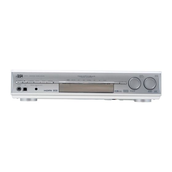
Page 7: Parts Identification
EFFECT button (37) * These buttons can be used for operating a DVD recorder (JVC products only) or DVD player, with the mode selector set to “DVR” or “DVD” (see page 46). If these buttons do not function normally, use the remote control supplied with your DVD recorder or DVD player. - Page 8 See pages in parentheses for details. Front Panel STANDBY/ON button and standby lamp (16, 20) 2 CC CONVERTER button (23) 3 SETTING button (30) 4 ADJUST button (35) 5 SURROUND button (44) 6 HDMI lamp (9, 21) 7 Source lamps DVR/DVD, VCR, VIDEO, TV, USB, FM, AM Display window 1 ANALOG indicator (21)
- Page 9 See pages in parentheses for details. Rear Panel 1 Power cord (14) 2 COMPONENT VIDEO (Y, P ) jacks (11 – 13) VIDEO(VCR) IN, DVR/DVD IN, MONITOR OUT 3 HDMI terminals (9) VIDEO(VCR) IN, DVR/DVD IN, MONITOR OUT 4 DIGITAL IN terminals (14) •...
-
Page 10: Getting Started
Getting started Before installation 7 General precautions • Be sure your hands are dry. • Turn the power off to all components. • Read the manuals supplied with the components you are going to connect. 7 Locations • Install the receiver in a location that is level and protected from moisture and dust. -
Page 11: Connecting The Fm And Am (Mw) Antennas
Connecting the FM and AM (MW) antennas Do not connect the AC power cord until all other connections have been made. If FM reception is poor, connect an outdoor FM antenna (not supplied). Black White FM antenna (supplied) AM (MW) antenna connection Connect the AM (MW) loop antenna (supplied) to the AM LOOP terminals: Connect the white cord to the AM EXT terminal, and connect the black cord to the H terminal. -
Page 12: Connecting The Speakers
Connecting the speakers Do not connect the AC power cord until all other connections have been made. 7 Speaker Layout Diagram (SB*) CAUTIONS: • Use speakers with the SPEAKER IMPEDANCE indicated by the speaker terminals (6 Ω – 16 Ω). •... -
Page 13: Connecting Video Components
Connecting video components Do not connect the AC power cord until all other connections have been made. 7 HDMI connection IMPORTANT: The HDMI video signals from the HDMI terminals are transmitted only through the HDMI MONITOR OUT terminal. Therefore, you cannot view the playback picture on the TV: –... - Page 14 For details on T-V LINK, refer also to the manuals supplied with the TV and the VCR. • Connect a SCART cable to EXT-2 terminal on the JVC’s T-V LINK compatible TV for the T-V LINK function. • Some video components support the data communication like T-V LINK. For complete details, refer also to the manuals supplied with these components.
- Page 15 7 Audio/video connection In addition to the HDMI terminals and SCART terminals, this receiver is equipped with three video terminals—composite video, S-video, and component video terminals, and two audio jacks—analog discrete 5.1 channel audio input jacks (DVD MULTI IN) and stereo audio jacks. •...
- Page 16 Do not connect the AC power cord until all other connections have been made. Connecting a DVD recorder or DVD player with its analog discrete output jacks (DVD MULTI IN): If your DVD recorder or DVD player has analog 5.1 channel output jacks, use the connection below. When a DVD-Audio disc is played back, the original high-quality multi-channel sounds can be reproduced by using this connection.
- Page 17 Do not connect the AC power cord until all other connections have been made. Turn off all components before making connections. • When you connect the components, refer also to their manuals. Connecting a VCR and another video component: White Composite video cable (not supplied) NOTES •...
-
Page 18: Connecting The Power Cord
7 Digital audio connection This receiver is equipped with three DIGITAL IN terminals— one digital coaxial terminal and two digital optical terminals— and one DIGITAL OUT terminal. To reproduce the digital sound, use the digital audio connection in addition to the analog audio connection methods described on pages 11 to 13. -
Page 19: Usb Connection
USB connection This receiver is equipped with a USB terminal on the front panel. You can connect your PC to this terminal and enjoy sound reproduced through your PC. When you connect your PC for the first time, follow the procedure below. -
Page 20: Precise Surround Setup
Precise Surround Setup By using Precise Surround Setup, you can optimize the speaker settings easily, quickly and systematically without troublesome adjustments. To obtain the best possible sound effect from the Surround/ DSP modes, set up the speaker and subwoofer information after all the connections are completed. - Page 21 Put on the microphones. • Insert the microphone with “L” into your left ear, the microphone with “R” your right ear. Example: Microphone with “L” Take your usual listening position with the microphones and the remote control. CAUTION: Keep quiet so that Precise Surround Setup can detect test tones properly.
- Page 22 Unplug the earphone-type microphones. • When unplugging the microphones, pull on the plug, not the cord itself. NOTES • Do not press any buttons on the remote control or the front panel of the receiver during Precise Surround Setup; otherwise, the receiver stops setting and returns to the normal operation mode.
-
Page 23: Troubleshooting For Precise Surround Setup
Troubleshooting for Precise Surround Setup When problems occur, a message appears on the display during Precise Surround Setup. In this case, refer to the following solution, then perform Precise Surround Setup again. • To restart Precise Surround Setup, press PSS on the remote control; however, when you have turned the receiver off for the solution, start from step again. -
Page 24: Basic Operations
Basic operations Source lamps Turn on the power Press STANDBY/ON (or remote control). The standby lamp goes off and the current source lamp lights in red. Current source name appears. To turn off the power (into standby): Press STANDBY/ON (or AUDIO on the remote control) again. -
Page 25: Selecting The Video And Audio Input Settings
7 Listening with headphones You can enjoy not only stereo software but also multi-channel software through the headphones. (Sounds are down-mixed to the front channels while playing multi-channel software.) Connect a pair of headphones to the PHONES jack on the front panel to activate the HEADPHONE mode. -
Page 26: Selecting The Digital Decode Mode
Selecting the digital decode mode When “HDMI” or “DIGITAL” is selected for the audio input setting (see page 21), this receiver automatically detects the incoming digital signal format and sets the digital decode mode to “DIGITAL AUTO.” • The DIGITAL AUTO indicator lights up on the display. If the following symptoms occur while playing Dolby Digital or DTS software with “DIGITAL AUTO”... -
Page 27: Turning Off The Power With The Sleep Timer
• The Sleep Timer is also canceled when you turn off the receiver. Making sounds natural JVC’s CC (Compression Compensative) Converter eliminates jitter and ripples, achieving a drastic reduction in digital distortion by processing the digital music data in 24 bit- quantization and by expanding the sampling frequency to 176.4 kHz (for fs 44.1 kHz signals)/192 kHz (for fs 48 kHz... -
Page 28: Tuner Operations
Tuner operations Tuner operations are mainly done from the remote control. NOTE When you have selected “FM” or “AM” by using SOURCE SELECTOR on the front panel, the remote control may not work for tuner operations. To use the remote control for tuner operations, select “FM”... -
Page 29: Selecting The Fm Reception Mode
Press the numeric buttons (0 – 9, h10) to select a channel number while the channel number position is flashing. • For channel number 5, press 5. • For channel number 10, press h10, 1, then 0. • For channel number 25, press h10, 2, then 5. Press MEMORY again while the selected channel number is flashing on the display. -
Page 30: Using The Radio Data System To Receive Fm Stations
Using the Radio Data System to receive FM stations Only the buttons on the remote control are used for Radio Data System operations. Radio Data System allows FM stations to send an additional signal along with their regular program signals. For example, the stations send their station names, as well as information about what type of program they broadcast, such as sports or music, etc. - Page 31 PTY codes News Ô Affairs Ô Info Ô Sport Ô Educate Ô Drama Ô Culture Ô Science Ô Varied Ô Pop M Ô Rock M Ô Easy M Ô Light M Ô Classics Ô Other M Ô Weather Ô Finance Ô Children Ô Social Ô Religion Ô...
-
Page 32: Switching To Broadcast Program Of Your Choice Temporarily
Switching to broadcast program of your choice temporarily Another convenient Radio Data System service is called “Enhanced Other Networks.” This allows the receiver to switch temporarily to a broadcast program of your choice (TA, NEWS, and/or INFO) from a different station except in the following case: •... -
Page 33: Basic Settings
Basic settings To obtain the best possible sound effect from the Surround/ DSP modes (see pages 39 to 44), you need to set up the speaker and subwoofer information after all the connections are completed. From pages 29 to 34, how to set speakers and other basic items of the receiver are explained. -
Page 34: Operating Procedure
Operating procedure 1, 7 3, 5 On the front panel ONLY: Before you start, remember... There is a time limit in doing the following steps. If the setting is canceled before you finish, start from step Ex.: When setting the DIGITAL IN 1 terminal Press SETTING. -
Page 35: Activating The Ex/Es/Pliix Setting-Ex/Es/Pliix
7 Setting the speaker distance The distance from your listening position to the speakers is one of the important elements to obtain the best possible sound effect from the Surround/DSP modes. By referring to the speaker distance, the receiver automatically sets the delay time of the sound through each speaker so that sounds through all the speakers can reach you at the same time. -
Page 36: Selecting The Main Or Sub Channel-Dual Mono
Selecting the main or sub channel— DUAL MONO You can select the playback sound (channel) you want while playing digital software recorded (or broadcasted) in Dual Mono mode (see page 41), which includes two monaural channels separately. When the receiver detects Dual Mono signals, the DUAL MONO indicator lights up on the display. -
Page 37: Using The Midnight Mode-Midnight Mode
7 Setting the low frequency effect attenuator —LFE ATT If the bass sound is distorted while playing back software encoded with Dolby Digital or DTS, set the LFE level to eliminate distortion. • This function takes effect only when the LFE signals come in. LFE 0dB Normally select this. -
Page 38: Selecting The Source For Hdmi Terminal And Component Video Jacks-Hdmi Select/Cmpnt Select
Selecting the source for HDMI terminal and COMPONENT VIDEO jacks—HDMI SELECT/CMPNT SELECT When you connect a video component other than DVD recorder and DVD player to the HDMI VIDEO(VCR) IN terminal or COMPONENT VIDEO jacks on the rear of the receiver, you need to select either “VIDEO”... -
Page 39: Sound Adjustments
Sound adjustments You can make sound adjustment to your preference after completing basic setting. Basic adjustment items You can adjust the following items. See pages in parentheses for details. • You cannot select the items which is not available with the current setting. -
Page 40: Adjusting The Speaker Output Levels
Adjusting the speaker output levels • SUBWFR LVL (subwoofer output level) • FRONT L LVL (left front speaker output level) • FRONT R LVL (right front speaker output level) • CENTER LVL (center speaker output level) • SURR L LVL (left surround speaker output level) •... -
Page 41: Reinforcing The Bass-Bass Boost
Reinforcing the bass—BASS BOOST You can boost the bass level—Bass Boost. • Once you have made an adjustment, it is memorized for each source. B BOOST ON Select to boost the bass level. The B.BOOST indicator lights up on the display. - Page 42 7 Adjusting the panorama control for Pro Logic IIx Music and Pro Logic II Music—PANORAMA This setting is available when Pro Logic IIx Music or Pro Logic II Music is activated for the analog or digital 2-channel sound signal. To activate Pro Logic IIx Music or Pro Logic II Music, see pages 43 and 44.
-
Page 43: Creating Realistic Sound Fields
Creating realistic sound fields Reproducing theater ambience In a movie theater, many speakers are located on the walls to reproduce impressive multi-channel sound, reaching you from all directions. With these many speakers, sound localization and sound movement can be expressed. Surround/DSP modes built in this receiver can create almost the same Surround sound as you can feel in a real movie theater. - Page 44 • If both “SURROUND SPK” and “CENTER SPK” are set to “NO” in the speaker setting (see page 30), JVC’s original 3D-PHONIC processing (which has been developed to create the surround effect through the front speakers only) is used.
-
Page 45: Introducing The Dsp Modes
When using the DAP mode, the sounds come out of all the connected and activated speakers. • If “SURROUND SPK” is set to “NO” in the speaker setting (see page 30), JVC’s original 3D-PHONIC processing (which has been developed to create the surround effect through the front speakers only) is used. -
Page 46: Using The Surround/Dsp Modes
7 All Channel Stereo mode (ALL CH STEREO) This mode can reproduce a larger stereo sound field using all the connected (and activated) speakers. This mode cannot be used if “SURROUND SPK” is set to “NO” in the speaker setting (see page 30). Sound reproduced from Sound reproduced from normal stereo... -
Page 47: Activating The Surround/Dsp Modes
7 About the DSP modes • The following DSP modes are available regardless of incoming signal type: HALL1, HALL2, LIVE CLUB, DANCE CLUB, PAVILION, THEATRE1, THEATRE2 • If multi-channel (more than 2 channels) digital signals are coming in, “MONO FILM” is not available. •... - Page 48 7 Selecting the Surround/DSP modes From the remote control: Select and play any source. • Surround/DSP modes are not available when multi- channel PCM (see page 41) signals recorded in DVD- Audio are coming in. See page 12 for details. •...
-
Page 49: Operating Other Jvc Products
JVC products. • Refer also to the manuals supplied with the other products. – Some JVC VCRs can accept two types of the control signals—remote codes “A” and “B.” This remote control can operate a VCR whose remote control code is set to “A.”... - Page 50 To change the remote control code for DVD recorder Some JVC DVD recorders can accept four types of control signals. You can assign one of the four codes to the remote control supplied for this receiver to operate your DVD recorder.
-
Page 51: Operating Other Manufacturers' Products
Operating other manufacturers’ products By changing the transmittable signals, you can use the supplied remote control to operate other manufacturers’ products. • Refer also to the manuals supplied with the other products. • To operate those components with the remote control, first you need to set the manufacturer codes each for the TV, VCR, STB, and DVD player. - Page 52 To change the transmittable signals for operating a VCR Press and hold VCR • Keep the button pressed until step Press VCR. Enter the manufacturer code using the numeric buttons (1 – 9, 0). See “Manufacturer codes for VCR” on the right. Release VCR Now, you can perform the following operation on the VCR: Turn on or off the VCR.
- Page 53 Yamaha Initial setting: 01 NOTE You cannot use this remote control to operate any manufacturers’ DVD recorders other than JVC’s. Manufacturer codes are subject to change without notice. If they are changed, this remote control cannot operate the equipment. is finished.
-
Page 54: Troubleshooting
No picture on the TV screen. HDMI signals do not come on. Use this chart to help you solve daily operational problems. If there are any problems you cannot solve, contact your JVC service center. For Precise Surround Setup, see the separated troubleshooting on pages 19. - Page 55 PROBLEM The remote control does not The remote control is not ready for your operate as you intend. intended operation. The remote control does not There is an obstruction blocking the work. remote sensor on the receiver. Batteries are weak. The mode selector is set to the incorrect position.
-
Page 56: Specifications
Specifications Designs and specifications are subject to change without notice. 7 Amplifier Output Power At stereo operation: Front channels: 120 W per channel, min. RMS, driven into 6 Ω at 1 kHz with no more than 10% total harmonic distortion. At surround operation: Front channels: 110 W per channel, min. - Page 57 © 2006 Victor Company of Japan, Limited 0606RYMMDWJEIN...