Rinnai ASPIRATION RHFE-750ETR Operation & Installation Manual
Power flued flamefire space heater
Hide thumbs
Also See for ASPIRATION RHFE-750ETR:
- Installation manual (24 pages) ,
- Installation manual (24 pages)
Table of Contents
Advertisement
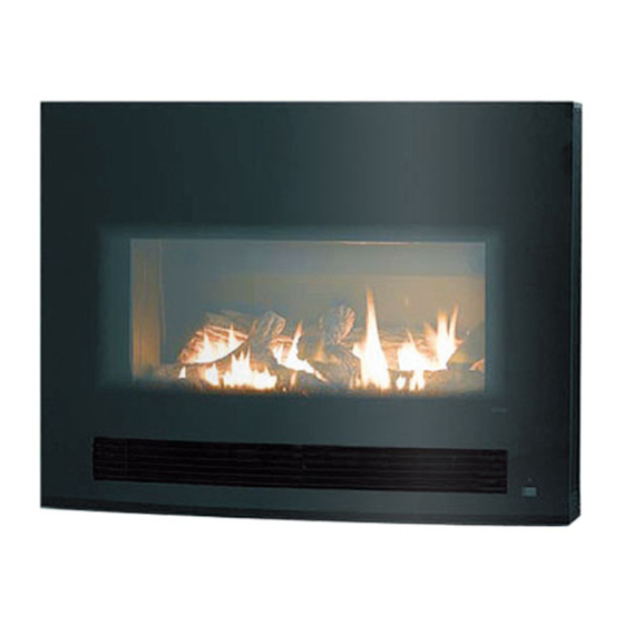
ASPIRATION
Power Flued Flamefire Space Heater
Operation / Installation Manual
MODEL RHFE-750ETR
This appliance shall be installed in accordance with:
• Manufacturer's Installation Instructions
• Current AS/NZS 3000, AS/NZS 3500 & AS 5601
• Local Regulations and Municipal Building Codes
This appliance must be installed, serviced and removed by an Authorised Person.
All Rinnai gas products
are A.G.A. certified.
Distributed and serviced in Australia under a Quality
System certified as complying with ISO 9001 by
SAI Global
Advertisement
Chapters
Table of Contents

Related Manuals for Rinnai ASPIRATION RHFE-750ETR


Summary of Contents for Rinnai ASPIRATION RHFE-750ETR
- Page 1 • Current AS/NZS 3000, AS/NZS 3500 & AS 5601 • Local Regulations and Municipal Building Codes All Rinnai gas products Distributed and serviced in Australia under a Quality This appliance must be installed, serviced and removed by an Authorised Person.
-
Page 2: Regulatory Information
The installation must also comply with the instructions supplied by Rinnai. Your Rinnai ASPIRATION space heater has been certified by the Australian Gas Association. The A.G.A. Certification Number is shown on the data plate of the appliance. -
Page 3: Table Of Contents
THE LOCK FUNCTION ......................10 CARE AND MAINTENANCE..................11 CLEANING ..........................11 FILTERS ............................. 11 LOUVRES........................... 12 GENERAL HEATER CHARACTERISTICS ................12 TROUBLE SHOOTING CHECKLIST ..................13 ERROR CODES ......................... 13 SERVICE ............................ 14 INSTALLATION MANUAL ..................16 CONTACT INFORMATION ..................29 Rinnai Operation Manual... -
Page 4: About Your New Aspiration Space Heater
LOG SET Remote control receiver, Indicator AIR DISCHARGE for filter/louvre blockages CONTROL PANEL ON/OFF BUTTON OPERATION INDICATOR Turns the heater On or Off. Indicates operation status TIMER INDICATOR ERROR DISPLAY Indicates timer program status. Displays error codes Rinnai Operation Manual... -
Page 5: Remote Control General Layout
• Avoid leaving the remote control in direct sunlight and do not place it close to the warm air discharge louvres of the heater. • Avoid dropping the remote control or getting it wet. Rinnai Operation Manual... -
Page 6: Remote Control Display
If the room temperature continues to rise when the heater is thermostatically turned down to its lowest setting the front burner will turn off leaving only the pilot flame operating. When the room temperature requires further heating the heater will automatically re-ignite to warm the room. Rinnai Operation Manual... -
Page 7: Safety
Young children should be supervised to ensure they do not play with the appliance. g. If the supply cord is damaged or requires replacing, it must be replaced by the manufacturer or the manufacturer's agent or similarly qualified person in order to avoid a hazard. Rinnai Operation Manual... - Page 8 However if operate this appliance. Heater must not be odours persist switch off the appliance and located below a power socket outlet. contact Rinnai. Rinnai Operation Manual...
-
Page 9: Basic Heater Operation
NOTE To re-activate the remote control press any button on the keypad. This returns the display to the previous mode. No information is transmitted from the controller to the heater when re-activating the display. Rinnai Operation Manual... -
Page 10: Turning On The Power
Timer 1 Set ON OFF Timer 2 Set ON OFF B. 16°C ~ 26°C (in 1°C steps) – Thermostatic control to pre-set temperature selected. Combustion rate varies to maintain the selected temperature. C. H (High) – Continuous combustion on high. Rinnai Operation Manual... -
Page 11: Flame Function
To replace batteries simply unscrew the battery compartment cover located on the back of the remote control anti-clockwise. When installing new batteries ensure that the correct polarity is observed, the polarity is engraved into the battery compartment. See the illustration on page 2. Rinnai Operation Manual... -
Page 12: Programmed Heater Operation
6:00 6:30 7:00 before the programmed ON time the micro-computer will ignite the burner. Room Average Timer temperature ignition programmed sensed ON time Earlier than Later than usual ignition usual ignition Rinnai Operation Manual... -
Page 13: Using The Timers
Time Timer 1 Set ON OFF The Remote Control Display will show "Lock" in the top left hand Timer 2 Set ON OFF corner. To cancel the Lock function hold down the Lock button for 3 seconds. Rinnai Operation Manual... -
Page 14: Care And Maintenance
RED to let you know that there is a problem. Once the Indicator is flashing if no action is taken the heater will eventually shut down to avoid overheating and a fault code of 14 will be displayed in the Error Display window. Rinnai Operation Manual... -
Page 15: Louvres
See page 9 for correct Timer(s) operation. Timer operates for a short period and then Room temperature may be higher than the set cuts out. temperature. Increase set temperature if desired. Cancel the Auto Off function. Rinnai Operation Manual... -
Page 16: Trouble Shooting Checklist
CARE AND MAINTENANCE TROUBLE SHOOTING CHECKLIST Use the following chart to help determine whether a service call is required, however if you are unsure about the way your heater is operating, contact Rinnai or your local agent. Fault Condition Possible Remedy... -
Page 17: Service
If the power supply cord or any other component of the heater are damaged, they must be replaced by Rinnai or a suitably qualified person. Any service or repair work should only be carried out by an authorised person. Rinnai has service and spare parts departments nationally see back cover for contact details. - Page 18 CUSTOMER NOTES Rinnai Operation Manual...
-
Page 19: Installation Manual
8. SETTING AIR GUIDE VANES (AIR FLOW CONTROL) ............ 25 9. INSTALLING THE FACIA PANEL .................. 25 10. INSTALLING THE TOP PANEL ..................25 11. COMMISSIONING ......................25 TECHNICAL INFORMATION ..................26 WIRING DIAGRAM ........................26 BLOCK DIAGRAM ........................26 Rinnai Installation Manual... -
Page 20: Installation General
INSTALLATION GENERAL PRODUCT SPECIFICATIONS Model: RHFE-750ETR Name: Aspiration General description: Inbuilt, glass or steel fronted, ceramic log space heater with forced convection heating and power flue system. Gas input rate: Natural Gas Propane Pilot and Low (MJ/hr): High, Extended flue / Direct flue (MJ/hr): 24.5 / 31.5... -
Page 21: Heater Location
In some cases curtains may need restraining. ENCLOSURE REQUIREMENTS As the Rinnai Aspiration has a cool outer casing it can be installed into existing Masonry fireplace or into a decorative fireplace constructed from combustible materials such as wood or plaster. -
Page 22: Gas Supply
This heater has a power cord with a three pin plug supplied. The power cord passes through a slot in the lower right of the appliance. If a left hand entry is required contact Rinnai for details. Rinnai recommend the heater be plugged into a 240V, 10A earthed power point. -
Page 23: Flue Installation
FLUE INSTALLATION TYPES OF FLUE INSTALLATIONS Consult the Rinnai Aspiration RHFE 750ETR ‘Flue Installation Manual’ included with the ‘On Wall’ or ‘Direct’ flue kits for detailed flue installation instructions. IMPORTANT Use only Rinnai Aspiration flue components with this appliance. Option... -
Page 24: Flue Terminal Location
NOTE AS 5601 are met. The flue system must be fully assembled and secured in place before the heater is installed into the enclosure. IMPORTANT Rinnai Installation Manual... -
Page 25: Heater Installation
The heater does not come supplied with flue components. These are purchased separately. NOTE ONLY Rinnai RHFE750ETR flue components can be used with this appliance. 2. CONNECTING THE APPLIANCE TO THE CONSUMER PIPING 240 VOLTS, RISK OF ELECTRICAL SHOCK! Isolate the electricity supply before removing any panels. -
Page 26: Heater Body Installation
Secure heater body through these points using appropriate fixings. 5. CONNECTING THE FLUE SYSTEM TO THE APPLIANCE Only Rinnai RHFE 750 ETR flue components MUST be used with this appliance. Connections between the heater and the flue system MUST BE made in IMPORTANT accordance with the Aspiration flue instructions supplied with the flue components. -
Page 27: Installing The Log Set
Place the right-hand bottom log into the combustion chamber on the opposite side to left-hand bottom log Replace combustion chamber glass panel and secure in place with the two retaining screws Rinnai Installation Manual... -
Page 28: Setting Air Guide Vanes (Air Flow Control)
Once installed explain to the householder the functions and operation of the heater and remote control. Remind the customer of the need for regular service and maintenance. Ensure the ‘Customer Record' on page i of this manual is filled in and that the booklet is handed to the customer. Rinnai Installation Manual... -
Page 29: Technical Information
Over Heat Thermistor 1,2 SV1~4 Main Solenoid Valve 1~4 Combustion Fan Motor Fan Control Circuit Remote Control Circuit Central Processing Unit Pilot Burner Front Burner REARB Rear Burner REARB(L) Rear Burner Left REARB(R) Rear Burner Right BLOCK DIAGRAM Rinnai Installation Manual... - Page 30 NOTES Rinnai Installation Manual...
- Page 31 NOTES Rinnai Installation Manual...
-
Page 32: Contact Information
Tel: (03) 9271 6625 Fax: (03) 9271 6622 Rinnai has a Service and Spare Parts network with personnel who are fully trained and equipped to give the best service on your Rinnai appliance. If your appliance requires service, please call our National Help Service Line. Rinnai recommends that this appliance be serviced every 2 years.