Lincoln Electric LN-25 Service Manual
Semiautomatic wire feeder
Hide thumbs
Also See for LN-25:
- Service manual (111 pages) ,
- Operator's manual (45 pages) ,
- Technical specifications (8 pages)
Table of Contents
Advertisement
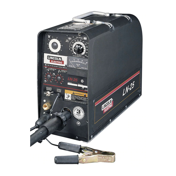
LN-25 PORTABLE CV/CC
SEMIAUTOMATIC WIRE FEEDER
For use with machines having Code Numbers:
Safety Depends on You
Lincoln arc welding and cutting
equipment is designed and built
with safety in mind. However,
your overall safety can be
increased by proper installation
... and thoughtful operation on
your part. DO NOT INSTALL,
OPERATE OR REPAIR THIS
EQUIPMENT WITHOUT READ-
ING THIS MANUAL AND THE
SAFETY PRECAUTIONS CON-
TAINED THROUGHOUT. And,
most importantly, think before you
act and be careful.
World's Leader in Welding and Cutting Products
22801 St. Clair Ave. Cleveland, Ohio 44117-1199 U.S.A. Tel. (216) 481-8100
9218
9219
9220
9383
9810
9811
9812
10148
10149
10150
SERVICE MANUAL
Sales and Service through Subsidiaries and Distributors Worldwide
SVM114-A
Premier Manufacturer of Industrial Motors
June 1995
Advertisement
Chapters
Table of Contents
Troubleshooting

Related Manuals for Lincoln Electric LN-25


Summary of Contents for Lincoln Electric LN-25
- Page 1 9218 9219 9220 9383 9810 9811 Safety Depends on You 9812 Lincoln arc welding and cutting 10148 equipment is designed and built 10149 with safety in mind. However, 10150 your overall safety can be increased by proper installation ... and thoughtful operation on your part.
- Page 2 Miami, Florida 33135 or CSA Standard W117.2-1974. A Free copy of “Arc Welding Safety” booklet E205 is available from the Lincoln Electric Company, 22801 St. Clair Avenue, Cleveland, Ohio 44117-1199. BE SURE THAT ALL INSTALLATION, OPERATION, MAINTENANCE AND REPAIR PROCEDURES ARE PER- FORMED ONLY BY QUALIFIED INDIVIDUALS.
-
Page 3: Safety
Electrical Code, all local codes and the manufacturer’s This can create fire hazards or overheat lifting chains or recommendations. cables until they fail. 6.c. Ground the equipment in accordance with the U.S. National 4.h. Also see item 7c. Electrical Code and the manufacturer’s recommendations. Mar. ‘93 LN-25... - Page 4 7.g. To prevent accidentally starting gasoline engines while turning the engine or welding generator during maintenance work, disconnect the spark plug wires, distributor cap or magneto wire as appropriate. ___________________________________________________ LN-25...
- Page 5 épaisse, pan- talons sans revers, et chaussures montantes. place. 5. Toujours porter des lunettes de sécurité dans la zone de soudage. Utiliser des lunettes avec écrans lateraux dans les zones où l’on pique le laitier. LN-25...
-
Page 6: Table Of Contents
LN-25 Option Chart ........ - Page 7 NOTES...
- Page 8 SA-200, -250 or SAE-300, -400 ......Invertec, CV300 and other newer Lincoln Power Sources ..
-
Page 9: Installation
INSTALLATION TECHNICAL SPECIFICATIONS – LN-25 VOLTAGE VOLTAGE Modes Range Constant Voltage (CV) 15-40 VDC (110VDC Maximum OCV) Constant Current (CC) RATED CURRENT RATED CURRENT Without Contactor With Contactor 500 Amps 60% Duty Cycle 300 Amps 60% Duty Cycle WIRE FEED SPEED WIRE SPEED RANGE 50 –... -
Page 10: Safety Precautions
POWER SOURCE CONNECTION the DC-250 is turned on. The LN-25 can be used with any DC welding power b. Connect electrode cable to the “Innershield/ source. A constant voltage power source is GMAW”... -
Page 12: Weld Cable Connection
A.2. 400Amps 500Amps TABLE A.2 ELECTRODE CABLE CONNECTION Instructions On units without an internal contactor route the Steel Wire Sizes: electrode cable through the oval hole in the LN-25 rear .068- ⁄ Cored KP450- ⁄ S17984 ⁄ (.062) Cored or Solid ⁄... - Page 13 NOTES LN-25...
- Page 14 Welding Capability ........LN-25 Instruments and Controls ......
-
Page 15: Operation
¥Wear eye, ear and body pro- WELDING CAPABILITY tection. The LN-25 will handle up to 500 Amp 60% duty cycle welding currents. However , when equipped with a K443-1 Contactor , the LN-25 will handle up to 300 Amp 60% duty cycle. -
Page 16: Instruments And Controls
OPERATION LN-25 INSTRUMENTS AND NOTE: CONTROLS 1. The Voltmeter will read zero if the LN-25 work clip lead is not connected to work, even if the elec Refer to Figure B.1 for control locations. trode is electrically ÒhotÓ to work. - Page 17 GAS POST PRE-FLOW TIMERS (OPTIONAL) the LN-25 work lead clip if the power source output is on. The clip will be electrically “HOT” to work if the Allows for variable adjustment of gas pre-flow & post- input electrode cable to the LN-25 is electrically “HOT”...
-
Page 18: Sequence Of Operation
COILS ® spool in a clockwise direction when dereeled from the bottom of the coil. The LN-25 is factory equipped with a K363-P Readi- c. Replace and tighten the locking collar. Reel ® Adapter which is required to load Lincoln 22 to 30 lb Readi-Reel coils. -
Page 19: Loading Wire Drive
ÒbirdnestÓ.) Keep gun in LN-25 gun holder when not feeding wire to prevent accidental arcing. c. Insert the free end through the incoming guide tube to the drive roll. -
Page 20: Presetting Wire Feed Speed
PRESETTING WIRE FEED SPEED The LN-25 permits accurate presetting of the desired wire feed speed, before welding, in both CV and CC wire feed modes. SETTING CONSTANT WIRE FEED SPEED (CV MODE) a. -
Page 21: Making A Weld
569 506 455 414 379 350 325 303 284 268 591 525 473 430 394 365 338 315 295 278 d. Connect the LN-25 Clip Lead to work and set Po 613 544 490 445 408 377 350 327 306 288 larity Switch to same polarity as electrode. -
Page 22: Welding
The gun trigger controls wire feed only. d. To stop welding, release the gun trigger and then pull the gun away from the work. Store the gun in the LN-25 insulated gun holder when not welding. WARNING PROCEDURE AT END OF COIL CYLINDER may explode if damaged. -
Page 23: Automatic Protection Shutdown
Improved performance can be obtained Do not use LN-25 models below Code 9200 with any o n C C p o w e r s o u r c e a p p l i c a t i o n s w i t h i n t h e TIG or Square Wave welding power sources. - Page 24 ......K443-1 LN-25 Contactor Kit ......
-
Page 25: Accessories
How to use T able C.1. Determine which Kit No. is to be used. Locate that Kit No. in the left hand vertical column. Scan horizontally to determine which LN-25 model is required and what additional kits may be required. TABLE C.1 LN-25 OPTION CHART O = CANNOT BE USED WITH X = REQUIRED Œ... -
Page 26: Optional Accessories
Installation instructions (M17587) are included with the (Factory Installed on K446 and K449 Models) kit. The kit permits the LN-25 to be used for Gas Metal Arc Welding (GMAW) processes with a GMA gun K434-1 GAS FLOW TIMER KIT cable. -
Page 27: Remote Output Control Options And Control Cable Assemblies
NOTE: If the K431-1 Remote Output Control Kit is the gun trigger is pressed, and a fixed burnback time installed but the LN-25 is to be used without the K432 delay to prevent electrode from sticking in the weld Remote Control Cable Assembly, then the Remote crater when the trigger is released. -
Page 28: K439 Remote Extension Cable Assembly
(2-4). NOTE: If the K624-1 42V Remote Output Control Module is installed but the LN-25 is to be used without K444-2 connects to power sources with a 14-pin the K625, K626 or K627 Remote Control Cable... - Page 29 .252 CONNECTOR MUST .260 BE INSULATED 1.00 IN THIS AREA 2.00 1.25 LN-25 Connector for 1/16 (.062) through 5/64 Wire .180 .160 .03 x 45 STYLE "B" "A" DIA. HOLE .495 MAX. LN-25 Cable Connector for .023 through .052 Wire DIA.
- Page 30 Adjusting Speed Sensor Module ......Calibration of LN-25 Wire Speed Dial ......
-
Page 31: Maintenance
G1757- 1 PC boards a 5 amp fuse was used to changed. interrupt the 667 lead. The LN-25 will not operate if the fuse is blown. The drive rolls for .045 and .052 cored electrode and ⁄... -
Page 32: Calibration Of Ln-25 Wire Speed Dial
An alternate means to measure wire feed speed follows: is as follows: 1. Be sure all power to the LN-25 is shut off at the a. Cut wire off at the end of the gun tip. power source. b. Press trigger to feed wire for exactly 30 seconds. - Page 33 NOTES LN-25...
- Page 34 Gas Solenoid ......... LN-25...
-
Page 35: Theory Of Operation
This The DC arc voltage from the power source is combination of welding cable, optional contactor, applied to the LN-25 through the electrode cable conductor block and gun cable constitute the and work sensing lead. This DC voltage is welding current path to the electrode wire. - Page 36 See Figure E.2. When drive motor and to activate any auxiliary circuits the LN-25 is connected to a constant current that may be incorporated within the LN-25. See (CC) power source, a variable wire feed speed Figure E.2.
- Page 37 The contactor , contactor PC board, and cold GAS SOLENOID inch switch are commonly incorporated in the LN-25. This feature enables the user to have an The gas solenoid feature permits the LN-25 to electrically ÒCOLDÓ gun even though the power be used for gas metal arc welding (GMA sources output terminals are electrically ÒHOTÓ.
- Page 38 Retest After Repair ........F-38 WARNING LN-25...
-
Page 39: Troubleshooting And Repair
How To Use Troubleshooting Guide WARNING Service and Repair should only be performed by Lincoln Electric Factory Trained Personnel. Unauthorized repairs performed on this equipment may result in danger to the technician and machine operator and will invalidate your factory warranty. For your safety and to avoid Electrical Shock, please observe all safety notes and precautions detailed throughout this manual. -
Page 40: Pc Board Troubleshooting Procedures
CAUTION complete. Sometimes machine failures appear to be due - If you return a PC board to The Lincoln to PC board failures. These problems can Electric Company for credit, it must be in the sometimes be traced to poor electrical con- static-shielding bag. -
Page 41: Troubleshooting Guide
NOTE: Many options and possible option combinations are available for the LN-25. In many cases, it is best to disconnect the options and test the LN-25 in its “basic” form. In this manner, many possible faulty circuits can be isolated and/or eliminated from the troubleshooting procedure. -
Page 42: Troubleshooting Guide
CAUTION If for any reason you do not understand the test procedures or are unable to perform the tests/repairs safely, contact the Lincoln Electric Service Department for technical troubleshooting assistance before you proceed. Call 216-383-2531 or 1-800-833-9353. LN-25... - Page 43 PC board. CAUTION If for any reason you do not understand the test procedures or are unable to perform the tests/repairs safely, contact the Lincoln Electric Service Department for technical troubleshooting assistance before you proceed. Call 216-383-2531 or 1-800-833-9353. LN-25...
-
Page 44: Gas Solenoid Valve And Solenoid Pc Board Test
GAS SOLENOID VALVE AND SOLENOID PC BOARD TEST WARNING Service and repair should only be performed by Lincoln Electric factory trained personnel. Unauthorized repairs performed on this equipment may result in danger to the technician or machine operator and will invalidate your factory warranty. -
Page 45: Test Procedures
1. Open the case door . Remove the wire reel by removing the retaining collar See Figure F .1. 2. Remove the three screws holding the control box cover in place and remove the control box cover . See Figure F .1. LN-25... - Page 46 7. The normal solenoid resistance is solenoid is hooked up, and then apply approximately 20 to 27 ohms. 12 VDC to the gas solenoid. 5. If the solenoid activates and allows gas flow, then the solenoid valve is good. LN-25...
- Page 47 SENSING LEAD SOLENOID PC BOARD 1. Apply at least 25 VDC but no more than 100 VDC to the LN-25 from the electrode cable to the work sensing lead. Make sure the polarity switch is set to match the polarity of the electrode cable.
- Page 48 4. Check for the presence of 10 VDC in the Electrical Diagrams Section. from lead 606(+) to lead 621(-). When the LN-25 trigger circuit is activated, The appropriate jumper plugs may be the voltage should drop to about used to isolate and check suspect 1 VDC.
-
Page 49: Hall Effect Module Test
F-12 HALL EFFECT MODULE TEST WARNING Service and repair should only be performed by Lincoln Electric factory trained personnel. Unauthorized repairs performed on this equipment may result in danger to the technician or machine operator and will invalidate your factory warranty . - Page 50 Do not remove the leads from the control board. See 2. Remove the three screws holding the Figure F.6 and Figure F.7. control box cover in place and remove the control box cover. See Figure F.1. LN-25...
- Page 51 HALL EFFECT MODULE TEST (continued) 4. Apply at least 25 VDC but no more approximately 6.0 VDC from lead than 100 VDC to the LN-25 from the 555(+) to lead 500( -). The value of electrode cable to the work sensing 6.0 VDC represents the correct...
-
Page 52: Wire Drive Motor Test
TROUBLESHOOTING AND REPAIR WIRE DRIVE MOTOR TEST WARNING Service and repair should only be performed by Lincoln Electric factory trained personnel. Unauthorized repairs performed on this equipment may result in danger to the technician or machine operator and will invalidate your factory warranty. - Page 53 See Figure F .8. For codes is low , the motor is grounded to the 9812 and below , remove the two motor case and should be replaced. motor leads 539(white) 541(black) from the control PC board. See Figure F .7. LN-25...
-
Page 54: Contactor Test
TROUBLESHOOTING AND REPAIR CONTACTOR TEST WARNING Service and repair should only be performed by Lincoln Electric factory trained personnel. Unauthorized repairs performed on this equipment may result in danger to the technician or machine operator and will invalidate your factory warranty. - Page 55 9812 and below , remove the two See Figure F .1. contactor coil leads from contactor PC board. See Figure F .10. 2. Remove the three screws holding the control box cover in place and remove the control box cover . See Figure F .1. LN-25...
- Page 56 6. If the contactor activates when the 12 be very high (infinite). If the resistance is VDC is applied, check the resistance always low, the contacts are “stuck” and the between the two large terminal studs contactor is faulty. Replace. with the contactor activated. The LN-25...
-
Page 57: Contactor Pc Board Replacement
¥ Observe all safety precautions detailed throughout this manual. Turn of f input power to the wire feeder . Only qualified technicians should perform installations, maintenance, and troubleshooting work on the machine. TOOLS REQUIRED Phillips head screwdriver LN-25... - Page 58 Troubleshooting Procedures at the plug J9 and plug J7 from the beginning of this section. contactor PC board. See Figure F .11. 2. Open the case door . Remove the wire reel by removing the retaining collar See Figure F .1. LN-25...
- Page 59 5. For codes 9812 and below , remove Figure F .10. Also for codes 9812 and the contactor coil leads and plug J7 below , remove plug J3 from the from the contactor PC board. See control PC board. See Figure F .12. LN-25...
- Page 60 11. Install the wire reel and retaining 8. For codes 10148 and above, install collar and close the case door. See plug J9 and plug J7 onto the Figure F.1. contactor PC board. See Figure F.11. LN-25...
-
Page 61: Control Pc Board Replacement
¥ Observe all safety precautions detailed throughout this manual. Turn of f input power to the wire feeder . Only qualified technicians should perform installations, maintenance, and troubleshooting work on the machine. TOOLS REQUIRED Phillips head screwdriver LN-25... - Page 62 PC board may have to be removed. 4. For codes 10148 and above, remove the four plugs J1, J2, J3 and J4. See Figure F .14A. FIGURE F.14B Ð CONTROL PC BOARD (CODES 9812 AND BELOW). G1757 G1757 LN-25...
- Page 63 9. For codes 10148 and above, install the four Molex type plugs J1, J2, J3 12. Install the wire reel and retaining and J4 onto the control PC board. collar and close the case door. See See Figure F.14A. Figure F.1. LN-25...
-
Page 64: Contactor Replacement
• Observe all safety precautions detailed throughout this manual. Turn off input power to the wire feeder. Only qualified technicians should perform installations, maintenance, and troubleshooting work on the machine. TOOLS REQUIRED Phillips head screwdriver 5/16" nutdriver 11/16" wrench LN-25... - Page 65 5. Remove the two 1 1/16" brass nuts 2. Remove the three screws holding the holding voltage sensing lead 67 and control box cover in place and remove the welding cables to the contactor the control box cover . See Figure F .1. LN-25...
- Page 66 13. Install the baf fle in front of the the LN-25. contactor . 9. Install a new contactor in the LN-25. 14. Install the control box cover and 10. Connect the contactor coil lead in-line secure by installing the three screws.
-
Page 67: Gas Solenoid Valve And/Or Solenoid Pc Board Replacement
¥ Observe all safety precautions detailed throughout this manual. Turn of f input power to the wire feeder . Only qualified technicians should perform installations, maintenance, and troubleshooting work on the machine. TOOLS REQUIRED Phillips head screwdriver 3/4" wrench Pliers LN-25... - Page 68 J11 from the solenoid PC board. control box cover in place and remove Also, disconnect the two solenoid the control box cover. See Figure F.1. leads from the gas solenoid valve, and disconnect the purge switch leads. See Figure F.17. LN-25...
- Page 69 Connect the leads to the gas solenoid gas solenoid valve to the assembly valve and purge switch. See Figure bracket. Remove the gas solenoid F.17. valve. 8. Remove the two screws mounting the solenoid PC board to the assembly bracket. Remove the solenoid PC board. LN-25...
- Page 70 PC board and See Figure F.1. connect the purge switch leads. See 16. Install the wire reel and retaining Figure F.18. Also, install plug J2 onto collar and close the case door. See the control board. See Figure F.12. Figure F.1. LN-25...
-
Page 71: Drive Motor And Gearbox Replacement And Access To Hall Effect Module
¥ Observe all safety precautions detailed throughout this manual. Turn of f input power to the wire feeder . Only qualified technicians should perform installations, maintenance, and troubleshooting work on the machine. TOOLS REQUIRED Phillips head screwdriver 3/4" wrench 5/8" wrench 7/16" wrench Slot head screwdriver LN-25... - Page 72 (539 and 541) reel by removing the retaining collar and the three hall ef fect module leads See Figure F .1. (500, 512 and 555) from the control board. See Figure F .7. 3. Remove the three screws holding the LN-25...
- Page 73 13. Install the wire reel and retaining onto the gearbox and secure with the collar and close the case door . See three screws, flat washers and Figure F .1. lockwashers. Install the rear end plate, lockwashers and screws. LN-25...
- Page 74 TROUBLESHOOTING AND REPAIR F-37 DRIVE MOTOR AND GEARBOX REPLACEMENT AND ACCESS TO HALL EFFECT MODULE (continued) FIGURE F.21 Ð DRIVE MOTOR REPLACEMENT . DRIVE MOTOR GEARBOX REAR END PLATE LOCKWASHER FLAT WASHER END PLATE MOUNTING SCREW LOCKWASHER DRIVE MOTOR MOUNTING SCREW LN-25...
-
Page 75: Retest After Repair
....Must operate when gun trigger is activated Contactor (optional) ....Must operate when gun trigger is activated LN-25... - Page 76 G-11 Codes 9812 and Below ....... . . G-13 LN-25...
- Page 77 NOTES LN-25...
-
Page 78: Electrical Diagrams
ELECTRICAL DIAGRAMS WIRING DIAGRAM — CODES 10148 AND ABOVE WIRING DIAGRAM - LN-25 TO REMOTE TIMER P.C. OR CONTACTOR WIRE SPEED DIAL BOARD P.C. BOARD RANGE SWITCH OPTIONAL REMOTE 530A N.D.,N.E. 500A KIT PLUG N.A. 622A 500A N.B. CONTACTOR P C BOARD... - Page 79 ELECTRICAL SYMBOLS PER E1537 NOTE: This diagram is for reference only. It may not be accurate for all machines covered by this manual. The specific diagram for a particular code is pasted inside the machine on one of the enclosure panels. LN-25...
- Page 80 NOTE: Lincoln Electric assumes no responsibility for liablilities resulting from board level troubleshooting. PC Board repairs will invalidate your factory warranty. Individual Printed Circuit Board Components are not available from Lincoln Electric. This information is provided for reference only. Lincoln Electric discourages board level troubleshooting and repair since it may compromise the quality of the design and may result in danger to the Machine Operator or Technician.
- Page 81 NOTE: Lincoln Electric assumes no responsibility for liablilities resulting from board level troubleshooting. PC Board repairs will invalidate your factory warranty. Individual Printed Circuit Board Components are not available from Lincoln Electric. This information is provided for reference only. Lincoln Electric discourages board level troubleshooting and repair since it may compromise the quality of the design and may result in danger to the Machine Operator or Technician.
- Page 82 Board repairs will invalidate your factory warranty. Individual Printed Circuit Board Components are not available from Lincoln Electric. This information is provided for reference only. Lincoln Electric dis- courages board level troubleshooting and repair since it may compromise the quality of the design and may result in danger to the Machine Operator or Technician.
-
Page 83: Control Pc Board Layout
R13,R14 RESISTOR-WW,5W,4.7K,5%,SQ RESISTOR-WW,5W,68,5%,SQ NOTE: Lincoln Electric assumes no responsibility for liablilities resulting from board level troubleshooting. PC Individual Printed Circuit Board Components are Board repairs will invalidate your factory warranty not available from Lincoln Electric. This information is provided for reference only . - Page 84 Board repairs will invalidate your factory warranty. Individual Printed Circuit Board Components are not available from Lincoln Electric. This information is provided for reference only. Lincoln Electric dis- courages board level troubleshooting and repair since it may compromise the quality of the design and may result in danger to the Machine Operator or Technician.
- Page 85 R13,R14 RESISTOR-WW,5W,4.7K,5%,SQ Lincoln Electric. NOTE: Lincoln Electric assumes no responsibility for liablilities resulting from board level troubleshooting. PC Individual Printed Circuit Board Components are Board repairs will invalidate your factory warranty not available from Lincoln Electric. This information is provided for reference only .
- Page 86 Board repairs will invalidate your factory warranty. Individual Printed Circuit Board Components are not available from Lincoln Electric. This information is provided for reference only. Lincoln Electric dis- courages board level troubleshooting and repair since it may compromise the quality of the design and may result in danger to the Machine Operator or Technician.
-
Page 87: Contactor Pc Board Layout
NOTE: Individual parts listed are not available from RESISTOR-MF,1/4W,1.82K,1% Lincoln Electric. NOTE: Lincoln Electric assumes no responsibility for liablilities resulting from board level troubleshooting. PC Individual Printed Circuit Board Components are Board repairs will invalidate your factory warranty not available from Lincoln Electric. This information is provided for reference only . - Page 88 Board repairs will invalidate your factory warranty. Individual Printed Circuit Board Components are not available from Lincoln Electric. This information is provided for reference only. Lincoln Electric dis- courages board level troubleshooting and repair since it may compromise the quality of the design and may result in danger to the Machine Operator or Technician.
- Page 89 R4,R24 RESISTOR-MF,1/4W,15.0K,1% Lincoln Electric. NOTE: Lincoln Electric assumes no responsibility for liablilities resulting from board level troubleshooting. PC Individual Printed Circuit Board Components are Board repairs will invalidate your factory warranty not available from Lincoln Electric. This information is provided for reference only .
- Page 90 G-15 G-15 NOTES LN-25...