Table of Contents
Advertisement
Advertisement
Chapters
Table of Contents

Related Manuals for Furuno RC18xx Series

Summary of Contents for Furuno RC18xx Series
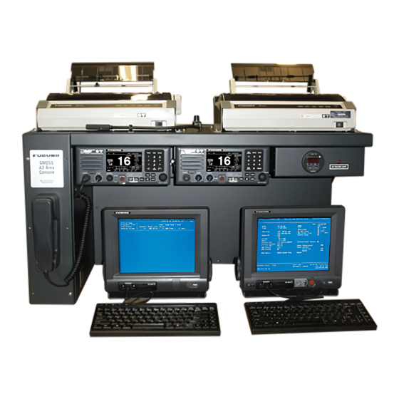
- Page 1 FURUNO USA A3 GMDSS CONSOLE RC18xx Series MODEL:...
- Page 2 FURUNO USA IME-GMD-40Z...
-
Page 3: Table Of Contents
TABLE OF CONTENTS 1. INTRODUCTION 2. MECHANICAL INSTALLATION RC1815/RC1825 Mechanical Layout RC1840 Mechanical Layout A3 GMDSS Console Mechanical Drawing 3 . CONSOLE WIRING RC18xx Electrical and NMEA/IEC-61162 Connections RC18xx Battery Requirements 4. RC1815/RC1825 EQUIPMENT INSTALLATIONS 4.1 DMC-5 4.2 Felcom 15 4.3 FM-8500 4.4 FS-1570/FS-2570 4.5 IB-583... -
Page 4: Felcom 15
TABLE OF CONTENTS 7. RC1840 EQUIPMENT SETUP 7.1 General 7.2 DMC-5 7.3 DP-6 7.4 DSC-60 7.5 Felcom 15 7.6 FM-8500 7.7 FS-5000 8. RC1815/RC1825 EQUIPMENT LISTS FM-8500 FS-1570/FS-2570 Felcom 15 IB-583 GMDSS Installation Materials Crate 9. RC1840 EQUIPMENT LISTS FS-5000 DP-6 Felcom 15 FM-8500... -
Page 5: Introduction
1. RC18xx Console Introduction 1.1 Introduction • The FURUNO USA GMDSS Console is an integrated package designed to meet the requirements for Sea Area A3. While other configurations are available, and much of the information is similar, this manual was compiled for use with the A3 configuration. -
Page 6: Mechanical Installation
2. Mechanical Installation 2.1 Mounting of the Console Refer to Furuno USA GMDSS Console Drawing The RC18xx Console is designed to be mounted in two distinct positions: • The first is to fasten the unit to a desk or base. Ten 3/8” holes have been provided to ensure a secure mounting to the selected surface. -
Page 7: Rc1815/Rc1825 Mechanical Layout
Keyboard PP-510 for FS-2570C PP-510 for and IB-583 Felcom 15 AC Failure FURUNO Label Light FS-2570C FM-8500 Meter IB-315 Handset Junction Box Printer Switch for FS-2570C and IB-583 Console Ground Connection FURUNO USA GMDSS DESCRIPTION RC1815 and RC1825 Mechanical Layout... -
Page 8: Rc1840 Mechanical Layout
IC-215 Keyboard Keyboard PP-510 for DSC-60 PP-510 for and DP-6 Felcom 15 AC Failure FURUNO Label Light DSC-60 FM-8500 Meter IB-315 Handset Junction Box Printer Switch for DSC-60 and DP-6 Console Ground Connection FURUNO USA GMDSS DESCRIPTION RC1840 Mechanical Layout... -
Page 9: A3 Gmdss Console Mechanical Drawing
A3 GMDSS Console Mechanical Drawing... -
Page 10: Console Wiring
Refer to RC1815/RC1825 and RC1840 Meter Box Assembly Drawing 3.1.1 Meter Box All power connections to the RC18xx series console are made to the Meter Box. Access to the Meter Box is made by removing four, countersunk phillips, screws from the bottom and sliding the cover back and down. On the inside of the cover is a mechanical layout of the box, to assist with installation. - Page 11 3. RC18xx Console Wiring 3.1 Electrical Connections (Continued) Refer to RC1815/RC1825 and RC1840 Meter Box Assembly Drawing 3.1.5 PR-850A Power Supply Determine the AC Input to be used with the PR-850A (Factory setting is for 220 VAC). Using the diagram supplied with the PR-850A, open the supply and set the transformer taps for the correct voltage.
-
Page 12: Rc18Xx Battery Requirements
RC18xx Battery Requirements Current / RC1815 RC1825 RC1840 Equipment Calculation Amps Amps Amps PP510 0.4A x 2 = DSC-60 1.0A = DP-6 1.6A = AC Fail Lamp 0.3A = Emer. Lamp 0.3A = Felcom 15 RX 0.9A = Felcom 15 TX 5A/2 = IB-583 0.6A =... -
Page 13: Rc1815/Rc1825 Equipment Installations
4. RC1815/RC1825 Equipment Installations 4.1 DMC-5 (Optional Equipment) Refer to the Operator’s/Installation Manual, DMC-5 and the RC1815/RC1825, DMC-5 Interconnect Drawing 4.1.1 Mounting 1) Mount the DMC-5 in an accessible area on the bridge. (Refer to the Operator’s/Installation Manual, DMC-5, Section 6) 4.1.2 Power Connections 1) Connect 24 VDC to the DMC-5 (Junction Board, TB10). - Page 14 4. RC1815/RC1825 Equipment Installations 4.2 Felcom 15 Installation Refer to Installation Manual, Felcom 15 4.2.1 IC-215 Communications Unit/Display 1) Mount the IC-215 in the front, desktop area, of the console on the right side. Using the four tapping screws provided. (Refer to the Pg.
- Page 15 4. RC1815/RC1825 Equipment Installations 4.3 FM-8500 Installation Refer to Installation Manual, FM-8500 4.3.1 Transceiver There are two FM-8500’s in the standard console configurations. One unit is mounted in the console, and will not require installation of a NMEA cable or power cable.
- Page 16 4. RC1815/RC1825 Equipment Installations 4.4 FS-1570/FS-2570 Installation Refer to Installation Manual, FS-1570 (150W) / FS-2570 (250W) 4.4.1 Control Unit 1) The FS-2570C (Control Unit) and HS2001 (Handset) have been mounted and wired into the console. 4.4.2 Transceiver Unit 1) The Transceiver is designed for bulkhead mounting using six tapping screws or bolts.
- Page 17 4. RC1815/RC1825 Equipment Installations 4.4 FS-1570/FS-2570 Installation (Continued) Refer to Installation Manual, FS-1570 (150W) / FS-2570 (250W) 4.4.4 Antenna Coupler AT-1560-15 or AT-1560-25 (Continued) 4) Remove the antenna coupler top housing by removing the 8 housing screws. 5) Install the control cable (000-130-484) from the antenna coupler to the transceiver.
- Page 18 4. RC1815/RC1825 Equipment Installations 4.4 FS-1570/FS-2570 Installation (Continued) Refer to Installation Manual, FS-1570 (150W) / FS-2570 (250W) 4.4.5 DSC/Watch Receiver Antenna (Continued) 4) Reassemble the transceiver. 4.4.6 NMEA/IEC-61162 Connection 1) Install a cable, Belden 8302 or equivalent, from the Felcom 15 Junction Box to the FS-1570/FS-2570 transceiver.
- Page 19 4. RC1815/RC1825 Equipment Installations 4.5 IB-583 NBDP Terminal Refer to Installation Manual, FS-1570 (150W) / FS-2570 (250W) 4.5.1 Mounting 1) Mount the IB-583 in the front, desktop area, of the console on the left side. Using the four tapping screws provided. (Refer to Pg.
- Page 20 5. RC1815/RC1825 Equipment Setup 5.1 General • When the installations are completed, proceed through the setup procedures. • The MMSI number and INMARSAT number will be needed to complete the setup and testing procedures. 5.1.1 Powering Up Equipment 1) Power on the PR850A. Power on the battery charger. 2) Install the printer paper and turn on the printers.
- Page 21 5. RC1815/RC1825 Equipment Setup 5.2 DMC-5 (Optional Equipment) Refer to the Operator’s/Installation Manual, DMC-5 5.2.1 General The setup and testing of the DMC-5 should be completed last. This unit expects all equipment, in the console, to already be operational. *Watch* Pos: NG 00:00 Manual input ? [ SET UP ] Key 1) After powering up the DMC-5 for the first time the screen should be as shown above.
- Page 22 5. RC1815/RC1825 Equipment Setup 5.2 DMC-5 (Continued) Refer to the Operator’s/Installation Manual, DMC-5 5.2.4 SES Input (INMARSAT C Terminal) *Watch* Pos: auto 00:00 VHF MF/HF 1) The display should appear as shown above, if it does continue to step 2. If not record the error and check the appropriate equipment.
-
Page 23: Felcom
5. RC1815/RC1825 Equipment Setup 5.3 Felcom 15 Refer to the Installation Manual, Felcom 15 5.3.1 General 1) Insert a good, formatted, floppy disk into the Terminal. 2) Power up the Felcom 15, the status screen should show OK indications and the GPS should indicate 3D. 5.3.2 IMN Input (Refer to Pg. -
Page 24: Fm-8500
5. RC1815/RC1825 Equipment Setup 5.4 FM-8500 Refer to the Installation Manual, FM-8500 5.4.1 General This setup must be performed on both FM-8500’s. 1) Power up the unit. 2) Press the [1] (Position) key. The Longitude/Latitude and UTC time should be displayed. This NMEA information is supplied by the Felcom 15. If it is not displayed check the NMEA cables and connections. - Page 25 5. RC1815/RC1825 Equipment Setup 5.4 FM-8500 (Continued) Refer to the Installation Manual, FM-8500 5.4.4 RT Settings System menu < > V P ID DSC RT CH PO 1) Using the arrow keys, select RT and press the [ENT] key. 2) Press the [2] key to select USA/WX ON, then press the [ENT] key. 5.4.5 Protection Setting System menu <...
-
Page 26: Fs-1570/Fs-2570
5. RC1815/RC1825 Equipment Setup 5.5 FS-1570/FS-2570 Refer to the Installation Manual, FS-1570 (150W) / FS-2570 (250W) 5.5.1 General 1) Power up the unit and press the [1/RT] key. 2) Press the [3/TEST]. Allow the test to complete and verify all checks are OK. 5.5.2 RT Operation 1) On each band, verify that the antenna automatically tunes when the [LOG/TUNE] key is pressed. -
Page 27: General
5. RC1815/RC1825 Equipment Setup 5.6 IB-583 NBDP Terminal Refer to the Installation Manual, FS-1570 (150W) / FS-2570 (250W) 5.6.1 General 1) Power up the unit. 2) Press the [F6] key, to enter the System menu. 3) Use the arrow keys to select Change. 4) Use the down arrow key to highlight Self Test. -
Page 28: Dmc-5
6. RC1840 Equipment Installations 6.1 DMC-5 (Optional Equipment) Refer to the Operator’s/Installation Manual, DMC-5 and the RC1840, DMC-5 Interconnect Drawing 6.1.1 Mounting 1) Mount the DMC-5 in an accessible area on the bridge. (Refer to the Operator’s/Installation Manual, DMC-5, Section 6) 6.1.2 Power Connections 1) Connect 24 VDC to the DMC-5 (Junction Board, TB10). -
Page 29: Dp-6
6. RC1840 Equipment Installations 6.2 DP-6 NBDP Terminal Refer to the Installation Manual, DP-6 6.2.1 Main Unit 1) Mount the DP-6 Main Unit. Route the provided cables from the console to the Main Unit. The following cables are provided in the console for the Main Unit (Refer to Pg. - Page 30 6. RC1840 Equipment Installations 6.3 DSC-60 DSC/Watch Receiver Refer to the Installation Manual, DSC-60 The DSC-60 DSC/Watch Receiver has been mounted and wired into the console. Only the antenna needs to be installed. A label is attached to the DSC-60 front panel to show if the unit is setup for an active or passive antenna.
-
Page 31: Felcom 15
6. RC1840 Equipment Installations 6.4 Felcom 15 Installation Refer to Installation Manual, Felcom 15 6.4.1 IC-215 Communications Unit/Display 1) Mount the IC-215 in the front, desktop area, of the console on the right side. Using the four tapping screws provided. (Refer to Pg. - Page 32 6. RC1840 Equipment Installations 6.5 FM-8500 Installation Refer to the Installation Manual, FM-8500 6.5.1 Transceiver There are two FM-8500’s in the standard console configurations. One unit is mounted in the console, and will not require installation of a NMEA cable or power cable.
- Page 33 6. RC1840 Equipment Installations 6.6 FS-5000 Refer to the Operator’s/Installation Manual, FS-5000 6.6.1 Transceiver Unit 1) Mount the Transceiver Unit. Leave at least 25mm space behind the transceiver. This will allow access for service. (Refer to Pgs. 3-10 and 3-11 of the Installation Manual) 2) Remove the front cover.
- Page 34 6. RC1840 Equipment Installations 6.6 FS-5000 (Continued) Refer to the Operator’s/Installation Manual, FS-5000 6.6.2 Control Unit (Continued) 6) Mount the handset hanger and connect to the HANDSET port on the control unit. 7) Reassemble the control unit and attach to the mounting bracket. 6.6.3 Antenna 1) The antenna is to be provided by the Dealer.
-
Page 35: Felcom
7. RC1840 Equipment Setup 7.1 General • When the installations are completed, proceed through the setup procedures. • The MMSI number and INMARSAT number will be needed to complete the setup and testing procedures. 7.1.1 Powering Up Equipment 1) Power on the PR850A and PR300. Power on the battery charger. 2) Install the printer paper and turn on the printers. -
Page 36: General
7. RC1840 Equipment Setup 7.2 DMC-5 (Optional Equipment) Refer to the Operator’s/Installation Manual, DMC-5 7.2.1 General The setup and testing of the DMC-5 should be completed last. This unit expects all equipment, in the console, to already be operational. *Watch* Pos: NG 00:00 Manual input ? [ SET UP ] Key 1) After powering up the DMC-5 for the first time the screen should be as shown above. - Page 37 7. RC1840 Equipment Setup 7.2 DMC-5 (Continued) Refer to the Operator’s/Installation Manual, DMC-5) 7.2.4 SES Input (INMARSAT C Terminal) *Watch* Pos: auto 00:00 VHF MF/HF 1) The display should appear as shown above, if it does continue to step 2. If not record the error and check the appropriate equipment.
- Page 38 7. RC1840 Equipment Setup 7.3 DP-6 NBDP Terminal Refer to the Installation Manual, DP-6 7.3.1 General 1) Power up the Terminal and main Units. 2) Press the [F6] key, to enter the System menu. 3) Use the arrow keys to select Change. 4) Use the down arrow key to highlight Self Test.
-
Page 39: Dsc-60
7. RC1840 Equipment Setup 7.4 DSC-60 DSC/Watch Receiver Refer to the Installation Manual, DSC-60 7.4.1 General 1) Power up the unit. 2) Press the [3/TEST] key, to start the self-test. 3) The test will run automatically and print the results. 4) Verify all test are OK and press the [CANCEL] key to return to normal operation. -
Page 40: Felcom
7. RC1840 Equipment Setup 7.5 Felcom 15 Refer to the Installation Manual, Felcom 15 7.5.1 General 1) Insert a good, formatted, floppy disk into the Terminal. 2) Power up the Felcom 15, the status screen should show OK indications and the GPS should indicate 3D. 7.5.2 IMN Input (Refer to Pg. -
Page 41: Fm-8500
7. RC1840 Equipment Setup 7.6 FM-8500 Refer to the Installation Manual, FM-8500 7.6.1 General This setup must be performed on both FM-8500’s. 1) Power up the unit. 2) Press the [1] (Position) key. The Longitude/Latitude and UTC time should be displayed. This NMEA information is supplied by the Felcom 15. If it is not displayed check the NMEA cables and connections. - Page 42 7. RC1840 Equipment Setup 7.6 FM-8500 (Continued) Refer to the Installation Manual, FM-8500 7.6.4 RT Settings System menu < > V P ID DSC RT CH PO 1) Using the arrow keys, select RT and press the [ENT] key. 2) Press the [2] key to select USA/WX ON, then press the [ENT] key. 7.6.5 Protection Setting System menu <...
-
Page 43: Fs-5000
7. RC1840 Equipment Setup 7.7 FS-5000 Refer to the Operator’s/Installation Manual, FS-5000 7.7.1 General 1) Power up the Transceiver and Control Head. 2) Start the self-test by pressing the [RCL] key, enter 9900 and then press the [ENT] key. This test should show OK. If an error code appears, record it. (Refer to Pg. - Page 44 7. RC1840 Equipment Setup 7.7 FS-5000 (Continued) Refer to the Operator’s/Installation Manual, FS-5000 7.7.4 Manual 2182 kHz Tuning Preset 1) Press the [2182] key. 2) Press the [TX TUNE] key, TX TUNING: OK will appear when the tuning is complete. 3) Open the coupler and record the status of the LED’s CR1-CR23.
-
Page 45: Rc1815/Rc1825 Equipment Lists
8. RC1815/RC1825 Equipment Lists FM-8500 (Installed Unit) Included in GMDSS Installation Materials Item Name Part No. Qty. Operator's Manual Operator's Guide Installation Manual Procedure for Distress Transmission on VHF FM-8500 Connector - FM-14 - 4 Pin 000-108-368 Connector - FM-14 - 6 Pin 000-116-185 Connector - FM-14 - 7 Pin 000-113-345... -
Page 46: Fs-1570/Fs-2570
8. RC1815/RC1825 Equipment Lists FS-1570/FS-2570 (Installed Unit) FS1570 TR/AT or FS2570 TR/AT Item Name Part No. Qty. Operator's Manual Operator's Guide Installation Manual Procedure for Distress Transmission on VHF and HF Antenna Coupler AT-1560/15 or AT-1560/25 Transciever FS-1570 or FS-2570 Copper Strap 000-572-187 Rubber Sleeve... -
Page 47: Felcom 15
8. RC1815/RC1825 Equipment Lists Felcom 15 IC-215 Communications Unit Item Name Part No. Qty. Operator's Manual Registration Form (INMARSAT) Installation Manual Distress Communications Guide IC-215 Terminal Unit Mini Keyboard 004-442-400 Floppy Disk 004-439-400 7 Amp Fuse 000-549-013 15 Amp Fuse 000-549-014 Tapping Screw 000-802-081... - Page 48 8. RC1815/RC1825 Equipment Lists IC-305 Distress Unit Item Name Part No. Qty. IC-305 Distress Unit Tapping Screw 000-802-079 Crimp-on Lug 000-538-113 Crimp-on Lug 000-108-424 IC-306 Alarm Unit Item Name Part No. Qty. IC-306 Alarm Unit Tapping Screw 000-802-079 Crimp-on Lug 000-538-113 Crimp-on Lug 000-108-424...
-
Page 49: Gmdss Installation Materials
8. RC1815/RC1825 Equipment Lists IB-583 NBDP Terminal Item Name Part No. Qty. IB-583 Terminal Unit Mini Keyboard 004-442-400 Floppy Disk 004-439-400 3 Amp Fuse 000-549-013 Tapping Screw 000-802-081 Grounding Wire, 2M 000-108-138 Label (C.S.D) 100-248-060 Label 100-248-051 Velcro, 60mm 100-237-680 Velcro, 30mm 100-237-670 GMDSS Installation Materials... -
Page 50: Crate
8. RC1815/RC1825 Equipment Lists Crate Item Name Part No. Qty. RC1800 Rack FUSA1800 FS-2570C Control Head FM-8500 VHF w/DSC PP-510 Printer... -
Page 51: Rc1840 Equipment Lists
9. RC1840 Equipment Lists FS-5000 - Transceiver Item Name Part No. Qty. Operator & Installation Manual FS-5000 Transceiver 000-056-738 FS-5000 - Cables Item Name Part No. Qty. Control Cable 000-106-043 FS-5000 - Control Unit Item Name Part No. Qty. Control Unit 000-056-731 Antenna Coupler 000-056-874... -
Page 52: Dp-6
9. RC1840 Equipment Lists DP-6 - Main Unit Item Name Part No. Qty. Main Unit - DP-6 Operator's Manual Operator's Guide Installation Manual Copper Strap 590-300-310 Tapping Screw 000-867-553 Flat Washer 000-864-128 DB25 000-120-946 DP-6 - Terminal Unit Item Name Part No. -
Page 53: Felcom 15
9. RC1840 Equipment Lists Felcom 15 IC-215 Communications Unit Item Name Part No. Qty. Operator's Manual Registration Form (INMARSAT) Installation Manual Distress Communications Guide IC-215 Terminal Unit Mini Keyboard 004-442-400 Floppy Disk 004-439-400 7 Amp Fuse 000-549-013 15 Amp Fuse 000-549-014 Tapping Screw 000-802-081... - Page 54 9. RC1840 Equipment Lists IC-305 Distress Unit Item Name Part No. Qty. IC-305 Distress Unit Tapping Screw 000-802-079 Crimp-on Lug 000-538-113 Crimp-on Lug 000-108-424 IC-306 Alarm Unit Item Name Part No. Qty. IC-306 Alarm Unit Tapping Screw 000-802-079 Crimp-on Lug 000-538-113 Crimp-on Lug 000-108-424...
-
Page 55: Item No
9. RC1840 Equipment Lists FM-8500 (Installed Unit) Included in GMDSS Installation Materials Item Name Part No. Qty. Operator's Manual Operator's Guide Installation Manual Procedure for Distress Transmission on VHF FM-8500 Connector - FM-14 - 4 Pin 000-108-368 Connector - FM-14 - 6 Pin 000-116-185 Connector - FM-14 - 7 Pin 000-113-345... - Page 56 9. RC1840 Equipment Lists DSC-60 Included in GMDSS Installation Materials Item Name Part No. Qty. Connector - FM-14 - 6 Pin 000-116-185 Connector - FM-14 - 7 Pin 000-113-345 Connector - FM-MP-7 000-108-859 Reducer - MP-7 - MP-M3A 000-108-860 Reducer - MP-7 - MP-M5A 000-108-861 Installation Manual Operator's Manual...
-
Page 57: Gmdss Installation Materials
9. RC1840 Equipment Lists GMDSS Installation Materials Item Name Part No. Qty. 28 v Bulb RC1-800-020 2 Amp Fuse, Mini ATM RC1-800-026 PL259 Connector RC1-500-060 Printer Paper 000-134-903 PP-510 Printer Operator's Manual Shore Based Maintenance Certificate Warranty Registration Form E Meter Owners Manual Installation Manual IME-GMD-40Z Dealers Manual... -
Page 58: Rc18Xx Parts List
Emergency Light Assy. RC1-800-011 Meter RC1-500-067 AC Failure Light Assy. RC1-500-069 AC Failure Light Label RC1-500-068 Furuno USA GMDSS Label RC1-800-034 Bulb, 3w, 24v (equiv. to 1820) RC1-800-020 Fuses, 2 Amp, Mini ATM Type RC1-800-026 PP-510 Roll Paper (Single Ply) AYT214... -
Page 59: Rc1815/Rc1825 Interconnect Drawing
000-146-652 24 VDC Handset 1 from NBDP FS-2570C Meter IC-305 Notes: FURUNO USA GMDSS 1) Local Supplied DESCRIPTION Factory Supplied 2) All External Connections Must be Fused. RC1815 / RC1825 Keyboard 3) Two FM-8500's supplied with each console, Interconnect Drawing... -
Page 60: Rc1840 Interconnect Drawing
DSC-60 Control Unit IC-305 NMEA from IC-315 Keyboard Notes: FURUNO USA GMDSS 1) Local Supplied DESCRIPTION Factory Supplied 2) All External Connections Must be Fused. RC1840 3) Two FM-8500's supplied with each console, Interconnect Drawing only one shown for simplification. -
Page 61: Rc1840 Detailed Interconnect Drawing
IC-215 NMEA Junction Box Junction FM-8500 Keyboard See Notes IC-305 Notes: FURUNO USA GMDSS 1) Local Supplied DESCRIPTION Factory Supplied Keyboard 2) All External Connections Must be Fused. RC1840 3) Two FM-8500's supplied with each console, Detailed Interconnect Drawing only one shown for simplification. -
Page 62: Meter Box Assembly Rc1815/Rc1825
Output +24VDC Inline Breakers FS-1570 Fuses FS-2570 FS-1570: 20 A Ground FS-2570: 35 A FURUNO USA GMDSS Notes: Part Number DESCRIPTION Meter Box Assembly 1) Local Supplied RC1-800-031 Factory Supplied RC1815 / RC1825 2) All External Connections Must be Fused. -
Page 63: Meter Box Assembly Rc1840
Inline Breakers Inline Breakers Fuses 20A Fuses FS-5000: 60 A Battery 24 VDC Ground Output PR300 FS-5000 FURUNO USA GMDSS Transceiver Notes: Part Number DESCRIPTION AC Input 100 to 240 Meter Box Assembly 1) Local Supplied RC1-800-031 Factory Supplied RC1840... -
Page 64: Felcom 15 Ic-315 Junction Box Connections
See RC1815 / RC1825 / RC1840 DMC-5 NMEA Interconnect Drawings RXD-H RXD + RXD-C RXD - FURUNO USA GMDSS Notes: 1) Local Supplied DESCRIPTION Factory Supplied Felcom 15 2) All External Connections Must be Fused. IC-315 Junction Box 3) Two FM-8500's supplied with each console, only one shown for simplification. -
Page 65: Rc1815/Rc1825, Dmc-5 Interconnect Drawing
TXD-C TD4-B TXD-C TXD-C RXD-H RXD-H RD4-A RXD-H RXD-C RD4-B RXD-C RXD-C DIST_CTR Frame Grnd Frame Grnd DESCRIPTION FURUNO USA GMDSS RC1815 / RC1825 Notes: DMC-5 1) Local Supplied Factory Supplied Interconnect Drawing 2) All External Connections Must be Fused. -
Page 66: Rc1840, Dmc-5 Interconnect Drawing
RXD-H RXD-H DMC IN-H RXD-H RXD-C DMC IN-C RXD-C RXD-C DMC CTR Frame Grnd FRAME GRND Frame Grnd DESCRIPTION FURUNO USA GMDSS Notes: RC1840 / DMC-5 1) Local Supplied Interconnect Drawing Factory Supplied 2) All External Connections Must be Fused.