Table of Contents
Advertisement
CURTIS PMC
235 East Airway Boulevard
Livermore, California 94550 USA
Tel: 925-961-1088
Fax: 925-961-1099
www.curtisinst.com
MANUAL
1 2 9 7
INTEGRATED TRACTION
& HYDRAULIC SYSTEM
C O N T R O L L E R
© 2001 CURTIS INSTRUMENTS, INC.
DESIGN OF CURTIS PMC 1200 SERIES
CONTROLLERS PROTECTED BY U.S.
PATENT NO. 4626750.
1297 Manual, p/n 36411
Rev. A: February 2001
Advertisement
Table of Contents
Troubleshooting

Related Manuals for Curtis 1297


Summary of Contents for Curtis 1297
- Page 1 1 2 9 7 INTEGRATED TRACTION & HYDRAULIC SYSTEM C O N T R O L L E R © 2001 CURTIS INSTRUMENTS, INC. DESIGN OF CURTIS PMC 1200 SERIES CONTROLLERS PROTECTED BY U.S. PATENT NO. 4626750. CURTIS PMC 235 East Airway Boulevard...
- Page 2 1297 Manual p/n 36411, Rev. A: February 2001 © 2001 CURTIS INSTRUMENTS, INC. CURTIS INSTRUMENTS, INC. 200 KISCO AVENUE MOUNT KISCO, NEW YORK 10549 U.S.A. 914-666-2971 914-666-2188 CURTIS PMC 235 EAST AIRWAY BOULEVARD LIVERMORE, CALIFORNIA 94550 U.S.A. 925-961-1088 925-961-1099 ADDITIONAL OFFICES located in...
-
Page 3: Table Of Contents
Interlock Braking Delay ..........27 1 2 3 4 5 6 7 8 9 0 1 1 2 3 4 5 6 7 8 9 0 1 1 2 3 4 5 6 7 8 9 0 1 Curtis PMC 1297 Manual... - Page 4 1 2 3 4 5 6 7 8 9 0 1 1 2 3 4 5 6 7 8 9 0 1 1 2 3 4 5 6 7 8 9 0 1 1 2 3 4 5 6 7 8 9 0 1 Curtis PMC 1297 Manual...
- Page 5 Service Pump ............. 63 1 2 3 4 5 6 7 8 9 0 1 1 2 3 4 5 6 7 8 9 0 1 1 2 3 4 5 6 7 8 9 0 1 Curtis PMC 1297 Manual...
- Page 6 1 2 3 4 5 6 7 8 9 0 1 1 2 3 4 5 6 7 8 9 0 1 1297 Program Menu ............78 1 2 3 4 5 6 7 8 9 0 1 1 2 3 4 5 6 7 8 9 0 1...
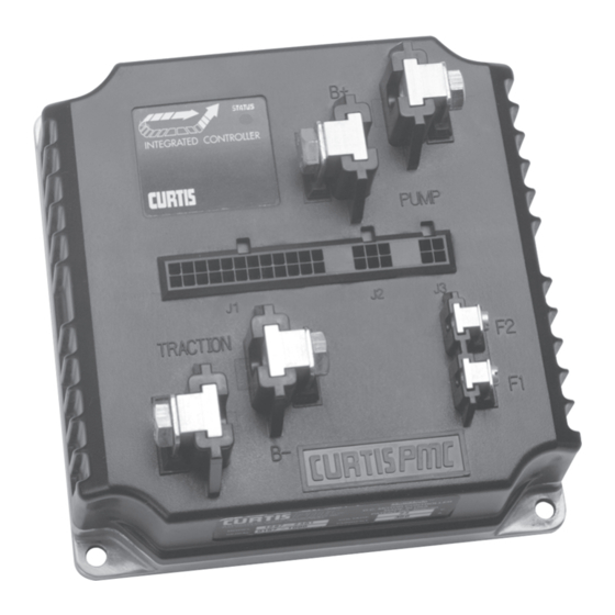
- Page 7 FIGURES . 1: Curtis PMC 1297 integrated traction and hydraulic system controller ........1 . 2: Mounting dimensions, Curtis PMC 1297 controller ....4 . 3: Standard wiring configuration, for applications without tiller multiplexer ........ 8 . 4: Standard wiring configuration, for applications with tiller multiplexer ........
- Page 8 Troubleshooting chart ............85 TABLE Status LED fault codes ............87 TABLE D-1: Programmable parameter ranges and default settings TABLE for generic 1297 models, Rev. 01 software ......D-1 E-1: Specifications, 1297 controller ........... E-1 TABLE viii Curtis PMC 1297 Manual...
-
Page 9: Overview
The pump section contains a half-bridge drive designed to provide smooth and efficient control of a series pump motor. In addition to controlling the pump motor, the 1297 controls the valves on the Lift cylinder’s hydraulic line and thus controls the hydraulic path for Lift and Lower operations. - Page 10 1 — OVERVIEW Like all Curtis PMC motor controllers, the 1297 offers superior operator control of motor speed. Features include: 150–350 amp separately excited regenerative traction motor controller Field current standard at 25 amps on 150 and 250 amp controllers, and at 35 amps on 350 amp controllers MultiMode™...
- Page 11 Schematic drawing of the 1312 generic circuit board is available at no cost to OEMs who want to design their own tiller multiplexers. Familiarity with your Curtis PMC controller will help you install and operate it properly. We encourage you to read this manual carefully. If you have questions, please contact the Curtis office nearest you.
-
Page 12: Installation And Wiring
INSTALLATION AND WIRING MOUNTING THE CONTROLLER The 1297 controller can be oriented in any position, and meets the IP53 ratings for environmental protection against dust and water. However, the location should be carefully chosen to keep the controller clean and dry. If a clean, dry mounting location cannot be found, a cover must be used to shield the controller from water and contaminants. - Page 13 EMC performance complies with applicable regulations; suggestions are presented in Appendix C. The 1297 controller contains ESD-sensitive components. Use appro- priate precautions in connecting, disconnecting, and handling the controller. See installation suggestions in Appendix C for protecting the controller from ESD damage.
-
Page 14: Connections: Low Current
2 — INSTALLATION & WIRING: Controller CONNECTIONS Low Current Connections Three low current connectors (J1, J2, J3) are built into the 1297 controller. They are located in a row on the top of the controller: 24-pin 6-pin 4-pin The 24-pin connector (J1) provides the logic control connections for the contactor drivers and switches that are wired directly to the vehicle. -
Page 15: Connections: High Current
A 4-pin low power connector (J3) is provided for the 13XX programmer. A complete programmer kit, including the appropriate connecting cable, can be ordered; see Curtis PMC programmer manual for further information on the various programmers available for programming Curtis PMC controllers. -
Page 16: Wiring: Standard Configuration, Without Multiplexer
CONTROL FUSE FUSE MAIN CONTACTOR Standard wiring configuration, Curtis PMC 1297 controller, Fig. 3 with no tiller multiplexer connected to the 6-pin connector. Power Wiring Traction motor armature wiring is straightforward, with the armature’s A1 connection going to the controller’s bus bar and its A2 connection going to the controller’s... - Page 17 If the main contactor coil is not wired to J1 Pin 17, the controller will not be able to open the main contactor in serious fault conditions and the system will therefore not meet EEC safety requirements. Curtis PMC 1297 Manual...
-
Page 18: Wiring: Standard Configuration, With Multiplexer
When J2 is not active, J1 Pins 12 and 24 are inputs THROTTLE HORN Ground for the forward and reverse switches—as shown in Figure 3. Standard wiring configuration, Curtis PMC 1297 controller, Fig. 4 with 1312 tiller multiplexer connected to the 6-pin connector (J2). Curtis PMC 1297 Manual... - Page 19 If the main contactor coil is not wired to J1 Pin 17, the controller will not be able to open the main contactor in serious fault conditions and the system will therefore not meet EEC safety requirements. Curtis PMC 1297 Manual...
-
Page 20: Wiring: Throttles
OEM to provide full throttle fault protection in vehicles using voltage throttles. Wiring for the most common throttles is described in the following text. If the throttle you are planning to use is not covered, contact the Curtis office nearest you. Curtis PMC 1297 Manual... -
Page 21: 5Kω-0 Two-Wire Resistive Throttle ("Type 1")
(see Section 3 , page 40) to Off; otherwise the controller will register a throttle fault. For ground-referenced 0–5V throttles, the controller will detect open breaks in the wiper input but cannot provide full throttle fault protection. Curtis PMC 1297 Manual... - Page 22 Pot Low input. For either throttle input, if the 0–5V throttle input (Pin 4 or 21) exceeds 5.5V relative to B-, the controller will register a fault and shut down. Curtis PMC 1297 Manual...
- Page 23 The 3-wire potentiometer is used in its voltage divider mode, with the voltage source and return being provided by the 1297 controller. Pot High provides a current limited 5V source to the pot, and Pot Low (Pin 22) provides the return path.
- Page 24 Curtis ET-XXX Electronic Throttle The Curtis ET-XXX provides a 0–5V throttle input and also Forward/Reverse inputs (traction throttle) or Lift/Lower inputs (hydraulic throttle) for the 1297 controller. Wiring for the ET-XXX is shown in Figure 9. When an electronic throttle is used, the Pot Low Check parameter (see Section 3 , page 40) must be set to Off;...
-
Page 25: 0-5Kω Two-Wire Resistive Throttle ("Type 3")
(Pin 12). The controller will behave as though no throttle is requested when the neutral switch is high, and will use the throttle value when the neutral switch is low. Curtis PMC 1297 Manual... -
Page 26: Wiring: Auxiliary Driver
WIRING: Auxiliary Driver ( REQUIRES MULTIPLEXER The 1297 controller provides an auxiliary driver at Pin 8. This low side driver, designed to energize a contactor coil, can be used to perform a variety of functions—such as engaging a brush motor. The output is rated at 2 amps, is overcurrent protected, and the turn-off is voltage clamped. -
Page 27: Wiring: Spyglass Display
WIRING: Spyglass Display The Curtis 840 Spyglass features an 8-character LCD display that sequences between hourmeter, BDI, and fault messages. Three indicator LEDs—hourmeter, BDI, and service—are also located on the face of the gauge. -
Page 28: Contactor, Switches, And Other Hardware
The contactor coils should be specified with a continuous rating at the nominal battery pack voltage. The 1297 controller provides a low-side contactor coil driver (at J1 Pin 17) for the contactor. The driver output is rated at 2 amps, is overcurrent protected at 3 amps, and is checked for open coil faults. - Page 29 3 amps. The 1297 controller provides a low-side load-holding valve solenoid driver at J1 Pin 18; this driver output is rated at 2 amps, and is overcurrent protected at 3 amps.
-
Page 30: Programmable Parameters (A: Traction / B: Hydraulic / C: Shared)
3 — PROGRAMMABLE PARAMETERS PROGRAMMABLE PARAMETERS The 1297 controller has nearly one hundred parameters that can be adjusted by means of a 13XX programmer. These programmable parameters allow various performance characteristics to be customized to fit the needs of individual applications or system operators. - Page 31 Emergency Reverse Time Limit For a list of the individual parameters in the order in Emergency Reverse Direction Intlk which they appear in the Program Menu, see Section 6: Other Traction Parameters Anti-tiedown Programmer Menus. Curtis PMC 1297 Manual...
-
Page 32: Traction Parameters
These parameters allow the vehicle to be tailored to a specific application, or to a specific operator’s preferences. The MultiMode™ feature of the 1297 controller allows operation in two distinct modes. These two modes can be programmed to provide two different sets of operating characteristics, which can be useful for different conditions. -
Page 33: Current Ratio
The braking current limit parameter allows adjustment of the maximum current the controller will supply to the motor during braking. The braking current limit is adjustable from 50 amps up to the controller’s full rated braking Curtis PMC 1297 Manual... -
Page 34: Braking Rate, M1-M2
first reduced. If the throttle decel rate is set low, deceleration is initiated abruptly. The transition is smoother if the throttle decel rate is higher; however, setting the throttle decel parameter too Curtis PMC 1297 Manual... -
Page 35: Interlock Braking Current Limit
RESTRAINT Because the 1297 controller is configured to provide regenerative braking, overspeed causes the controller to create a braking current and thus limit or “restrain” the overspeed condition. The restraint parameter determines how strongly the control- ler tries to limit the vehicle speed to the existing throttle setting. -
Page 36: Variable Braking
If a fixed amount of braking force is preferred, the variable braking parameter should be programmed Off. With variable braking Off, the control- ler applies the full programmed braking current as soon as direction is reversed. Curtis PMC 1297 Manual... -
Page 37: Electromagnetic Brake Type
When set to zero, there is no delay and the brake driver opens as soon as the interlock switch is opened and the sequencing delay expires. This parameter is not valid when brake driver option 0 is selected (see Table 2). Curtis PMC 1297 Manual... -
Page 38: Table 2: Configuration Options: Electromagnetic Brake Driver
Brake Driver turns off even if controller is not in neutral state.* The neutral state is reached when the traction throttle is in neutral, no direction is selected (both direction switches open), and any braking is completed. Curtis PMC 1297 Manual... -
Page 39: Speed Parameters
The interlock override feature is useful in situations where it is necessary to move the vehicle but there is not room to lower the tiller—for example, in a corner. Curtis PMC 1297 Manual... -
Page 40: Load Compensation
However, too much load compensation can result in jerky vehicle starts and speed oscillation (“hunting”) when the vehicle is unloaded. The load compensation parameter is tuned as part of the vehicle perfor- mance adjustment process (Section 5). Curtis PMC 1297 Manual... -
Page 41: Throttle Parameters
— PROGRAMMABLE TRACTION PARAMETERS: Throttle Throttle Parameters THROTTLE TYPE The 1297 controller accepts a variety of throttle inputs. Instructions are provided in Section 2 for wiring the most commonly used throttles: 5kΩ–0 and 0–5kΩ 2-wire rheostats, 3-wire pots (single-ended or wigwag), 0–5V throttles (single-ended or wigwag), current sources (single-ended or wigwag), and the Curtis ET-XXX electronic throttle. -
Page 42: Throttle Deadband
(throttle types 1 and 2). 40% Deadband 0.2V 2.1V (0Ω) (3.0kΩ) 10% Deadband 0.2V 3.0V (0Ω) (4.5kΩ) 0% Deadband 0.2V 3.3V (0Ω) (5.0kΩ) Throttle Type 2 (0–5V, single-ended) 40% Deadband 2.1V 10% Deadband 0.7V 0% Deadband 0.2V Curtis PMC 1297 Manual... - Page 43 5kΩ pot resistance. Neutral Controller Using a pot of greater or lesser resistance will give 100% Deadband Output different values for the deadband points. Throttle Max parameter set at 100%. Curtis PMC 1297 Manual...
-
Page 44: Throttle Maximum
3.0V (2.0kΩ) (4.5kΩ) Throttle Type 2 (0–5V, single-ended) 0.2V 100% Throttle Max 40% Deadband 2.1V 90% Throttle Max 40% Deadband 4.5V 2.1V 90% Throttle Max 10% Deadband 0.7V 4.5V 60% Throttle Max 10% Deadband 0.7V 3.1V Curtis PMC 1297 Manual... - Page 45 For throttle types 1 and 3, the deadband points are defined in terms of the nominal 5kΩ pot resistance. Neutral Controller Using a pot of greater or lesser resistance will give 100% Deadband Output different values for the deadband points. Curtis PMC 1297 Manual...
-
Page 46: Throttle Map
Figures 16 and 17. Controller output is always a percentage of the range defined by the speed parameters (the range between the creep speed and maximum speed settings). Curtis PMC 1297 Manual... - Page 47 The throttle map operates within the window established by the Creep Speed, Max Speed, Throttle Deadband, and Throttle Max parameters, as shown in Figure 18. Creep Speed and Max Speed define the controller’s output range, while Throttle Deadband and Throttle Max define the throttle’s active Curtis PMC 1297 Manual...
-
Page 48: Pot Low Check
It is recommended that the pot low check parameter be set to On in any application where a resistive throttle is used. This will provide maximum throttle fault detection and provide the safest possible vehicle operation. Curtis PMC 1297 Manual... -
Page 49: Field Parameters
Field Min and Field Max values. As shown in Figure 19, the field map parameter adjusts the field current at a point halfway between the programmed Field Map Start current and the full armature current (which is the controller’s Curtis PMC 1297 Manual... -
Page 50: Field Check
On. In applications where the motor field is too low to provide valid fault data (< 5 amps at 97% PWM), this parameter should be programmed Off. In most applications, it should be programmed On. Curtis PMC 1297 Manual... -
Page 51: Emergency Reverse Parameters
As soon as the emergency reverse button is released, the controller sets the drive output to zero regardless of whether a direction or throttle is still being requested. The emergency reverse direction interlock parameter defines how Curtis PMC 1297 Manual... -
Page 52: Other Traction Parameters
To start the vehicle, the controller must receive both an interlock switch input and a KSI input before receiving a throttle input greater than 25%. Controller operation will be disabled immediately if throttle demand is greater than 25% Curtis PMC 1297 Manual... -
Page 53: Sro
Sequencing delay (see page 57) can be used to provide a brief delay before SRO inhibits controller output, if desired. Curtis PMC 1297 Manual... -
Page 54: Hydraulic Parameters
The 1297 controls the speed of the pump motor, and also the valves on the Lift cylinder’s hydraulic line. By so doing, it controls the hydraulic path for Lift and Lower operations. -
Page 55: Pump Acceleration Rate
100% output to 0% output to the pump motor when the hydraulic throttle is reduced from full to none, or when the Lift switch is opened. The pump decel rate is adjustable from 0.1 to 3.0 seconds. Curtis PMC 1297 Manual... -
Page 56: Lift Lockout Parameters
>25% when the interlock switch is closed. The hydraulic inhibit parameter can be programmed On or Off. Sequencing delay (see page 57) can be used to provide a brief delay before controller output is inhibited. Curtis PMC 1297 Manual... -
Page 57: Valve Control Parameters
— PROGRAMMABLE HYDRAULIC PARAMETERS: Valve Control Valve Control Parameters The 1297 controls the operation of the load-hold valve and the proportional lowering valve, as shown in Figure 21. By so doing, it controls the hydraulic path for Lift and Lower operations. Some hydraulic systems have a proportional lowering valve but no load-hold valve. -
Page 58: Lowering Valve Current Deceleration Rate
During Lower, the lowering valve opens and gravity returns the fluid to the reservoir. When the Lower is completed, the lowering valve closes and this check valve plus the check valve at the pump keep the hydraulic fluid in place. Curtis PMC 1297 Manual... -
Page 59: Hydraulic Throttle Parameters
(Section 2). HYD THRTL TYPE The 1297 controller accepts a variety of hydraulic throttle inputs. Instructions are provided in Section 2 for wiring the most commonly used throttles: 3-wire pots (single-ended or wigwag), 0–5V throttles (single-ended or wigwag), cur- rent sources (single-ended or wigwag), and the Curtis ET-XXX electronic throttle. -
Page 60: Fig. 21 Effect Of Adjusting The Hydraulic Throttle Deadband Parameter
1.7V 3.3V 10% Deadband 4.5V 0.5V 2.3V 2.7V 0% Deadband 0.5V 2.5V 4.5V Notes: Voltages shown are at the pot wiper relative to B-. Hydraulic Throttle Max parameter set at 100%. Neutral Controller 100% Deadband Output Curtis PMC 1297 Manual... -
Page 61: Hydraulic Throttle Maximum
3.3V 4.3V 90% Throttle Max 10% Deadband 0.7V 2.3V 2.7V 4.3V 60% Throttle Max 10% Deadband 1.3V 2.3V 2.7V 3.7V Note: Voltages shown are at the pot wiper relative to B-. Neutral Controller 100% Deadband Output Curtis PMC 1297 Manual... -
Page 62: Hydraulic Throttle Map
So, in these examples, the throttle map is a percentage of the 0–80% output range; a 40% throttle map setting will give 32% output at half throttle (40% of 80% = 32%). Controller output will begin Curtis PMC 1297 Manual... -
Page 63: Output Response To Throttle Demand
(32% output at half throttle) HYDRAULIC THROTTLE INPUT (percent of active range) For Lower operations in applications using proportional lowering valves, the throttle maps are similar to those shown in Figures 23 and 24 for Lift Curtis PMC 1297 Manual... -
Page 64: Variable Lift
When a non-proportional lowering valve is used, the variable lower param- eter has only a slight effect. When programmed On, it will cause the point at which the valve snaps open to be reached more or less quickly depending on the amount of throttle applied. Curtis PMC 1297 Manual... -
Page 65: Shared Parameters
The main contactor open delay is programmable from 0 to 40 seconds. MAIN CONT DIAG The main contactor diagnostics parameter, when set to On, performs ongoing checks to ensure that the main contactor has closed properly each time it is Curtis PMC 1297 Manual... -
Page 66: Multiplexer Enable Parameter
Multiplexer Parameter MUX ENABLE The multiplexer enable parameter, when programmed On, enables the J2 connector—and thus the multiplexer—as shown in Figure 4, page 10. When the multiplexer parameter is programmed Off, the J2 connector is inactive. Curtis PMC 1297 Manual... -
Page 67: Hourmeter Parameters
Hourmeter “Preset” Settings The 1297 controller is shipped from the factory with each of its three hourmeters preset to 0. If the controller is being installed in a new vehicle, these presets do not need to be adjusted. -
Page 68: Set Total Hours
The pump service hours parameter is used to set the timer for the next scheduled pump motor maintenance. The pump service timer can be adjusted between 0.0 and 50.0, in 0.1 increments, with 25.0 being equivalent to 2,500 hours (25.0 × 100). Curtis PMC 1297 Manual... -
Page 69: Total Disable Hours
PUMP FAULT SPD The pump fault speed parameter sets the maximum pump motor speed in the event the pump disable timer expires or the total disable timer expires; it can be adjusted between 0–100% of Pump Max Speed. Curtis PMC 1297 Manual... -
Page 70: Service Total
Off to indicate the appropriate service has been performed. SERVICE PUMP When the pump service timer expires, the controller automatically sets the service pump parameter On. The user must then program the service pump parameter Off to indicate the appropriate service has been performed. Curtis PMC 1297 Manual... -
Page 71: Service Traction
2.04 Empty volts (VPC) 1.73 1.90 Custom values can be entered based on specific batteries in consultation with a Curtis applications engineer. RESET VOLTS The reset voltage parameter sets the voltage that is used to detect the 100% state-of-charge point on a battery with no load. Whenever this voltage is present for 6 seconds (except during regenerative braking) the BDI is reset to 100%. -
Page 72: Installation Checkout
LED diagnostic code in Section 7 (Diagnostics and Troubleshooting). When the problem has been corrected, it may be necessary to cycle the keyswitch in order to clear the fault. Curtis PMC 1297 Manual... - Page 73 If your application has a multiplexer, cycle the Lift and Lower switches on the multiplexer also. Drive the vehicle to a location that will provide enough room for the hydraulic functions to be tested; if indoors, be sure the ceiling height is adequate. Curtis PMC 1297 Manual...
-
Page 74: Fig . 26: Bench Test Setup For Verifying And Adjusting
The wiring can be expanded to conduct a complete functional test on the bench; if you want to do this, contact Curtis for further information. The complete in-vehicle installation checkout, as described in Steps 1–14, should still be conducted before the vehicle is operated. -
Page 75: Vehicle Performance Adjustment
5 — VEHICLE PERFORMANCE ADJUSTMENT VEHICLE PERFORMANCE ADJUSTMENT The 1297 controller is a very powerful vehicle control system. Its wide variety of adjustable parameters allow many aspects of vehicle performance to be optimized. This section provides explanations of what the major tuning param- eters do and instructions on how to use these parameters to optimize the performance of your vehicle. - Page 76 8. If a bidirectional (wigwag) throttle assembly is being used, the STEP procedure should be repeated for the reverse direction. The Throttle Deadband value should be selected such that the throttle operates correctly in both forward and reverse. Curtis PMC 1297 Manual...
- Page 77 6. If a wigwag throttle is being used, repeat the procedure for the STEP reverse direction. The Throttle Max value should be selected such that the throttle operates correctly in both forward and reverse. Curtis PMC 1297 Manual...
- Page 78 5 — VEHICLE PERFORMANCE ADJUSTMENT: Traction Tuning Tuning the Controller to the Motor The 1297 controller has the flexibility to be tuned to nearly any separately excited motor from any manufacturer. Parameters in the 13XX programmer’s Program Menu allow full control of the motor’s maximum armature current during driving and braking and full control of the motor’s maximum and...
- Page 79 The Field Min and possibly also the Field Map parameter should be increased until the indications of arcing stop. Decreasing the Field Map Start parameter will also help to move operation back into the safe commutation region. Curtis PMC 1297 Manual...
- Page 80 Field Min setting does not sufficiently reduce the vehicle’s top speed. 4. Scroll up the Program Menu until the Max Speed parameter is STEP visible in the display. While driving the vehicle with the Field Curtis PMC 1297 Manual...
- Page 81 . If the intent is to make the loaded speed less than the unloaded STEP speed (for reasons of safety, efficiency, or reduced motor heating), then: (i) Unload the vehicle and drive it on flat ground with full throttle applied. When the vehicle reaches maximum speed, observe the Curtis PMC 1297 Manual...
- Page 82 1. Set the Decel Rate based on the desired time for the vehicle to STEP stop upon release of throttle when traveling at full speed with full load. If the vehicle brakes too abruptly when the throttle is released, increase the Decel Rate. Curtis PMC 1297 Manual...
- Page 83 Accel Rate. 3. If the transition is too slow: decrease the Taper Rate and set STEP Creep Speed to 5% or greater. Secondary adjustments can be made by decreasing the Accel Rate or increasing the Current Ratio. Curtis PMC 1297 Manual...
- Page 84 : To determine whether NOTE the controller’s armature current is at its set value during ramp climbing, read the Arm Current value in the programmer’s Test Menu. Curtis PMC 1297 Manual...
-
Page 85: Hydraulic System Tuning
Nonetheless, it is important that the effect of these programmable parameters be understood in order to take full advantage of the 1297 controller’s powerful features. Please refer to the descriptions of the applicable parameters in Section 3 if there is any question about what any of them do. -
Page 86: Programmer Menus
The first four menus are controller-specific, and are presented below. The items are listed in these menus in the order in which they appear in the actual menus displayed by the 13XX programmer. Depending on the specific 1297 model you have, some of the items may not appear. - Page 87 Pump motor acceleration rate, in seconds PUMP ACCEL Pump motor deceleration rate, in seconds PUMP DECEL Hydraulic throttle input signal type HYD THRTL TYPE Neutral deadband, as % of hydraulic throttle range HYD THRTL DB (Menu continues on next page.) Curtis PMC 1297 Manual...
- Page 88 Voltage considered 100% state of charge, in volts FULL VOLTS Voltage considered 0% state of charge, in volts EMPTY VOLTS Voltage at which state of charge resets to 100%, in volts RESET VOLTS Multiplexer inputs enabled: on/off MUX ENABLE Curtis PMC 1297 Manual...
- Page 89 Off: To resume normal operation after emergency reversing has been completed, the operator must cycle the interlock switch. Hydraulic throttle types (see Hydraulic Throttle Wiring in Section 2) Type 2: single-ended 0–5V throttles and 3-wire pots Type 4: wigwag 0–5V throttles and 3-wire pots Curtis PMC 1297 Manual...
-
Page 90: 1297 Test Menu
Lowering valve duty cycle, as % LV PWM Lift switch: on/off LIFT INPUT Lower switch: on/off LOWER INPUT Main contactor: open/closed MAIN CONT Electromagnetic brake: on/off E-M BRAKE Horn driver: on/off HORN INPUT Load-hold valve driver: on/off LOAD HOLD Curtis PMC 1297 Manual... -
Page 91: 1297 Diagnostics Menu
6 — PROGRAMMER MENUS: Diagnostics Menu 1297 DIAGNOSTICS AND DIAGNOSTIC HISTORY This is a list of the possible messages you may see displayed when the program- mer is operating in either of the Diagnostics modes. The messages are listed here in alphabetical order for easy reference. -
Page 92: Diagnostics And Troubleshooting
7 — DIAGNOSTICS & TROUBLESHOOTING DIAGNOSTICS AND TROUBLESHOOTING The 1297 controller provides diagnostics information to assist technicians in troubleshooting pump system problems. The diagnostics information can be obtained by observing the appropriate display on a 13XX programmer, the fault codes issued by the Status LED, or the fault display on the Spyglass gauge. Refer to the troubleshooting chart (Table 5) for suggestions covering a wide range of possible faults. -
Page 93: Table 5 Troubleshooting Chart
1. Emergency reverse wire or check wire EMR REV WIRING open. main contactor welded 1. Main contactor stuck closed. MAIN CONT WELDED 2. Main contactor driver shorted. [chart continues on next page] Curtis PMC 1297 Manual... - Page 94 4. Wrong throttle type selected. hydraulic throttle high at interlock 1. Improper sequence of interlock and HYD INHIBIT throttle inputs. 2. Misadjusted throttle pot. 3. Interlock switch open. 4. Sequencing delay too short. 5. Wrong throttle type selected. Curtis PMC 1297 Manual...
-
Page 95: Led Diagnostics
7 — DIAGNOSTICS & TROUBLESHOOTING LED DIAGNOSTICS A Status LED is built into the 1297 controller. It is visible through a window in the label on top of the controller. This Status LED displays fault codes when there is a problem with the controller or with the inputs to the controller. During normal operation, with no faults present, the Status LED flashes steadily on and off. -
Page 96: Spyglass Diagnostics
( 3 , 2 ) and the corresponding Spyglass message is CODE 32. Preliminary on Verso page is set with right edge at 7 and 7/8, and the top (as on the Recto page) at 1/4. Curtis PMC 1297 Manual... -
Page 97: Maintenance
8 — MAINTENANCE MAINTENANCE There are no user serviceable parts in the Curtis PMC 1297 controller. No attempt should be made to open, repair, or otherwise modify the controller. Doing so may damage the controller and will void the warranty. -
Page 98: Appendix A Glossary Of Features And Functions
Access rights Each programmable parameter is assigned an access level (OEM or User) that defines who is allowed to adjust it. On generic 1297 models, all the program- mable parameters are assigned OEM access levels; see Table D-1. On OEM- specified models, the OEM designates the access level for each parameter. - Page 99 10% of throttle). This feature helps to prevent rollback when starting uphill with low throttle—see Section 3 , page 31. Current limiting Curtis PMC controllers limit the traction motor’s drive current and the pump motor current to their programmed maximum values—see Section 3 , page 24, and Section 3 , page 46.
- Page 100 , page 43. Environmental protection The 1297 controller is housed in a rugged ABS plastic case providing environ- mental protection that meets the requirements of IP53. The controller should be kept clean and dry to ensure long life. Additional protection is recommended if the controller is mounted in a location exposed to dirt or water splash.
- Page 101 When a fault is detected, the appropriate fault code is signalled. If the fault is critical, the controller is disabled. More typically, the fault is a remediable condition and temporary. The faults covered by the 1297 controller’s automatic fault detection system are listed in Table 5—see Section 7, page 85.
- Page 102 Section 5: Vehicle Performance Adjustment. Full bridge The 1297 controller uses a full bridge design for control of the traction motor’s field winding. This eliminates the need for external direction contactors. The result is a higher reliability product that is smaller and simpler to install.
- Page 103 MultiMode™ The MultiMode™ feature of the 1297 controller allows the vehicle to be operated with two distinct sets of characteristics. Typically, Mode 1 is pro- grammed for slow precise indoor maneuvering and Mode 2 for faster, long...
- Page 104 The operator uses the mode switch to select Mode 1 (switch open) or Mode 2 (switch closed). Multiplexer (MUX) The Curtis PMC 1312 tiller multiplexer provides a 4-wire serial interface for all tiller functions. The typical wiring configuration for applications using the multiplexer is shown in Figure 4, page 10.
- Page 105 Regenerative braking The 1297 controller uses regenerative braking to slow the vehicle to a stop and to reduce speed when traveling downhill. Regenerative braking means that the energy used to slow the vehicle is channeled back into the batteries, resulting in longer vehicle range between charges.
- Page 106 Status LED A built-in Status LED (Light Emitting Diode) is visible through the label located on top of the 1297 controller. The Status LED flashes a 2-digit fault identification code when a fault is detected by the controller. The fault code continues to flash until the fault has been corrected and the fault condition has been cleared.
- Page 107 , page 33, and Section 3 , page 51. Tuning The 1297 controller provides a variety of programmable parameters to assist in tuning the vehicle to meet the customer’s needs. Section 5: Vehicle Performance Adjustment presents information and procedures for tuning specific operating characteristics on any vehicle.
- Page 108 PWM, field, and pump sections are disabled. Welded contactor check The 1297 controller checks for a welded main contactor at startup. If a welded contactor is detected, the controller inhibits its output until the fault is removed and the keyswitch power is cycled.
-
Page 109: Fig . B-1: Mounting Dimensions, Curtis Pmc Standard
(1.25) 89 (3.5) 52 (2.06) (0.25) 102 (4.0) RIGHT-HAND OPERATION LEFT-HAND OPERATION COM. N.O. N.C. N.C. N.O. COM. WITH MICROSWITCH: PB-6 WITH MICROSWITCH: PB-9 WITHOUT MICROSWITCH: PB-5 WITHOUT MICROSWITCH: PB-10 Dimensions in millimeters and (inches) Curtis PMC 1297 Manual A-12... -
Page 110: Fig . B-3: Mounting Dimensions, Curtis Pmc Footpedal
APPENDIX A: GLOSSARY APPENDIX B: THROTTLES Mounting dimensions, Curtis PMC footpedal FP-2. Fig. B-3 ≈ 15 ° 1.8 m 244 (9.6) 112 (4.4) (6 ft) (4.4) N.O. COM. WIRING: = throttle input = switch, common GREEN / BLACK / WHITE... -
Page 111: Fig . B-4: Mounting Dimensions, Curtis Throttle Wp-45 Cp
Fig. B-5 6 × 6 (0.24 × 0.24) dimensions, Curtis VIS TC 3×12 electronic speed control device (ET series). ∅ M5 (3.90) (0.94) (1.73) (0.94) (2.72) 116 ° (0.87) (1.73) (0.87) Dimensions in millimeters and (inches) Curtis PMC 1297 Manual A-14... - Page 112 100 hours will typically generate lower emissions than new brushes because there is less arcing after they are properly seated. The motor drive output from Curtis PMC controllers can also make a contribution to rf emissions. This output is a pulse width modulated square wave with rather fast rise and fall times that are rich in harmonics.
- Page 113 Radiated paths are created when the controller circuitry is immersed in an external field. This coupling can be reduced by enclosing the controller in a metal box. Some Curtis PMC motor controllers are enclosed by a heat sink that also provides shielding around the controller circuitry, while others are unshielded.
- Page 114 ELECTROSTATIC DISCHARGE (ESD) Curtis PMC motor controllers contain ESD-sensitive components, and it is therefore necessary to protect them from ESD damage. Electrostatic discharge (ESD) immunity is achieved either by providing sufficient distance between...
-
Page 115: Programmable Parameters
APPENDIX D PROGRAMMABLE PARAMETERS The 1297’s programmable parameters are listed below in alphabetical order (by display name), along with the default access levels, minimum and maximum allowable values, and default settings that are standard on generic models. Cross references to the main entry in the manual are also provided. - Page 116 VARIABLE LOWER — page 56 4=wigwag The rated armature current for the pump motor depends on the controller model: 1297-22XX (200 amps), 1297-23XX (200 amps), 1297-24XX (300 amps); the default setting is the maximum value. Curtis PMC 1297 Manual A-19...
- Page 117 APPENDIX D: PROGRAMMABLE PARAMETERS APPENDIX A: GLOSSARY Table D-1 continued The 1297’s remaining parameters are listed below. For these lists, Program Menu order is used rather than alphabetical order. 1297 DEFAULT DEFAULT DESCRIPTION PARAMETER ACCESS VALUE VALUE SETTING UNITS IN MANUAL...
-
Page 118: Specifications
APPENDIX E: SPECIFICATIONS APPENDIX A: GLOSSARY APPENDIX E SPECIFICATIONS Table E-1 SPECIFICATIONS: 1297 CONTROLLER Nominal input voltage 24 V PWM operating frequency 16 kHz Electrical isolation to heatsink 500 V ac (minimum) KSI input voltage (minimum) 16.8 V KSI input current (no contactors engaged) 80 mA without programmer;...