Table of Contents
Advertisement
Manual
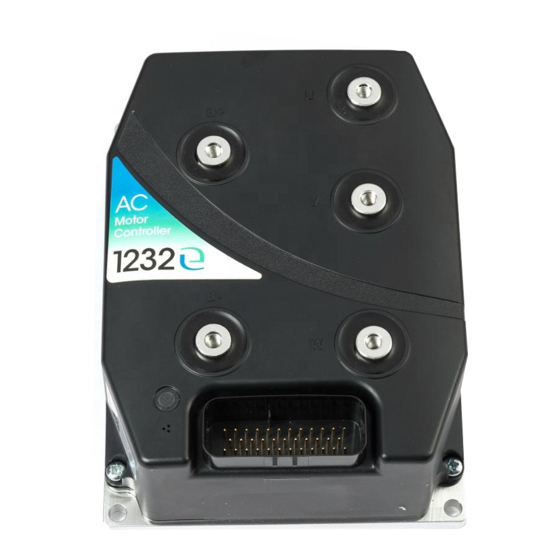
Models 1232E/34E/36E/38E
and 1232SE/34SE/36SE
Enhanced AC Controllers
for Induction Motors
and Surface Permanent Magnet Motors
» Software Version OS 30.0 «
Read Instructions Carefully!
Specifications are subject to change without notice.
© 2015 Curtis Instruments, Inc. ® Curtis is a registered trademark of Curtis Instruments, Inc.
© The design and appearance of the products depicted herein are the copyright of Curtis Instruments, Inc.
Curtis Instruments, Inc.
200 Kisco Avenue
Mt. Kisco, NY 10549
www.curtisinstruments.com
53134, OS30 11/24/2015
Advertisement
Table of Contents
Troubleshooting

Related Manuals for Curtis 1232E


Summary of Contents for Curtis 1232E
- Page 1 Specifications are subject to change without notice. © 2015 Curtis Instruments, Inc. ® Curtis is a registered trademark of Curtis Instruments, Inc. © The design and appearance of the products depicted herein are the copyright of Curtis Instruments, Inc. 53134, OS30 11/24/2015...
-
Page 3: Table Of Contents
8. VEHICLE CONTROL LANGUAGE......... 106 9. DIAGNOSTICS AND TROUBLESHOOTING ....137 10. MAINTENANCE ..............145 Vehicle Design Considerations appendix a EN13849 Compliance appendix b Programming Devices appendix c Specifications, 1232E/34E/36E/38E appendix d and 1232SE/34SE/36SE Controllers Curtis 1232E/34E/36E/38E & 1232SE/34SE/36SE Manual,... -
Page 4: Table Of Contents
2 4 N O V E M B E R 2 0 1 5 FIGURES / TABLES FIGURES fig. 1: Curtis 1232E/SE, 1234E/SE, 1236E/SE, 1238E controllers ... 1 fig. 2a: Mounting dimensions, Curtis 1232E/SE controller ....3 fig. 2b: Mounting dimensions, Curtis 1234E/SE controller ....4 fig. -
Page 5: Overview
1232SE, 1234E, 1236E, and 1238E. The E and SE models look similar, and share the same standard features. Like all Curtis controllers, the E and SE models offer superior operator control of motor drive performance. Features include:... - Page 6 Read and apply the information in this manual. The Installation/Wiring, Initial Setup, and Tuning Guide sections are critical to proper operation of your con- troller. For technical support, contact the Curtis distributor where you obtained your controller or the Curtis sales-support office in your region.
-
Page 7: Installation And Wiring
INSTALLATION AND WIRING MOUNTING THE CONTROLLER The outline and mounting hole dimensions for the 1232E/SE controller are shown in Figure 2a, for the 1234E/SE controller in Figure 2b, and for the 1236E/SE and 1238E controllers in Figure 2c. When an Ampseal plug housing is mated with the 35-pin logic receptacle, these controllers meet the IP65 requirements for envi- ronmental protection against dust and water. - Page 8 Wear safety glasses, and use properly insulated tools to prevent shorts. — Charging or discharging generates hydrogen gas, which can LEAD ACID BATTERIES build up in and around the batteries. Follow the battery manufacturer’s safety recom- mendations. Wear safety glasses. Curtis 1232E/34E/36E/38E & 1232SE/34SE/36SE Manual,...
- Page 9 Appendix A. These controllers contain ESD-sensitive components. Use appropriate precautions in connecting, disconnecting, and handling the controller. See installation suggestions in Appendix A for protecting the controller from ESD damage. Curtis 1232E/34E/36E/38E & 1232SE/34SE/36SE Manual,...
-
Page 10: Table 1: High Current Connections
Motor phase U. Motor phase V. Motor phase W. Lug assembly: 1232E/SE and 1234E/SE models Five aluminum M6 terminals are provided. Lugs should be installed as follows, using M6 bolts sized to provide proper engagement (see diagram): • Place the lug on top of the aluminum terminal, followed by a high-load safety washer with its convex side on top. - Page 11 Low current signal wires should not be run parallel to the motor cables. When necessary they should cross the motor cables at a right angle to minimize noise coupling. Curtis 1232E/34E/36E/38E & 1232SE/34SE/36SE Manual,...
- Page 12 All other low current wiring The remaining low current wiring should be run according to standard prac- tices. Running low current wiring parallel to the high current wiring should always be avoided. Curtis 1232E/34E/36E/38E & 1232SE/34SE/36SE Manual,...
-
Page 13: Table 2: Low Current Connections
Generic switch input #5. Sw_5 * The related VCL columns are vital when writing VCL code (see Section 8). VCL “functions” are used to access the various I/Os; VCL “references” are predefined names for specific pins. Curtis 1232E/34E/36E/38E & 1232SE/34SE/36SE Manual,... - Page 14 Unregulated low power Ext_Supply_Current +12V output. 26 +5V Out Regulated low power 5_Volts_Output +5V output. Ext_Supply_Current 27 Pot2 High Pot high connection for a 3-wire brake pot. 28 Serial TX Serial transmit line for Setup_Serial display or flash update. Curtis 1232E/34E/36E/38E & 1232SE/34SE/36SE Manual,...
- Page 15 Sw_8 Typically used as the Reverse switch. 34 CAN Term L Low connection for the CAN bus termination jumper. 35 CANL CAN bus low. Setup_CAN Setup_Mailbox Send_Mailbox etc. Pin 30 not connected on 1232E/SE controllers. Curtis 1232E/34E/36E/38E & 1232SE/34SE/36SE Manual,...
-
Page 16: Fig. 3: Basic Wiring Diagram
J1-7 J1-18 I/O GROUND POT LOW CURTIS 1232E/34E/36E/38E, 1232SE/34SE/36SE MODEL 840 CONTROLLER DISPLAY * 1232E and 1232SE do not include ANALOG OUT. Fig. 3 Basic wiring diagram, Curtis 1232E/SE, 34E/SE, 36E/SE, and 38E motor controllers. Curtis 1232E/34E/36E/38E & 1232SE/34SE/36SE Manual,... -
Page 17: Switch Input Wiring
These controllers have very flexible I/O and wiring configurations; you may wish to contact your Curtis distributor or support engineer to discuss your particular application. SWITCH INPUT WIRING The following inputs are dedicated to specific functions when the parameter... -
Page 18: Fig. 4: Wiring For Type 1 Throttles
Wiring for the most common throttles is described in the following text and shown in the accompanying illustrations. If a throttle you are planning to use is not covered, contact your Curtis distributor or support engineer. Throttle Type 1 For these 2-wire resistive potentiometers, shown in Figure 4, full throttle request corresponds to 0 Ω... -
Page 19: Fig. 5: Wiring For Type 2 Throttles
Curtis ET-XXX Electronic Throttle KEYSWITCH KSI (Pin 1) WHT/GRN WHT/BRN GREEN I/O Ground Return (Pin 7) ORANGE Throttle Pot Wiper input (Pin 16) BLACK Forward input (Pin 22) BLACK/WHITE Reverse input (Pin 33) WHITE connector Curtis 1232E/34E/36E/38E & 1232SE/34SE/36SE Manual,... -
Page 20: Fig. 6: Wiring For Type 3 Throttles
When a 3-wire pot is used, the controller provides full fault protection. When a voltage throttle is used, the controller will detect open breaks in the wiper input but cannot provide full throttle fault protection. Curtis 1232E/34E/36E/38E & 1232SE/34SE/36SE Manual,... - Page 21 CAN communication messages as the source of the throttle signals. If you have questions regarding this throttle type, contact your Curtis distributor or support engineer. Setting the Throttle Type to Type 5 also allows the throttle and brake pot inputs to be redefined by a VCL program for uses other than throttle or...
- Page 22 The two digital output lines can also be read as inputs, and are therefore included in this group. The lines at pins 24 and 8 can also be used as analog inputs, and are included in that group as well. Curtis 1232E/34E/36E/38E & 1232SE/34SE/36SE Manual,...
- Page 23 150 kΩ 150 kΩ 24, 33, 14) (pins 19, 20) 150 kΩ Model 150 kΩ 191 kΩ specific 24-36V models = 7.5 kΩ, 36-48V = 12 kΩ, 48-80V = 33 kΩ, 72-96V = 36 kΩ Curtis 1232E/34E/36E/38E & 1232SE/34SE/36SE Manual,...
- Page 24 KTY sensor must be the end connected to I/O Ground (pin 7). These lines can also be used as digital inputs, and are included in that group as well (see page 19). Curtis 1232E/34E/36E/38E & 1232SE/34SE/36SE Manual,...
- Page 25 filtered PWM signal and has about 1% ripple. The 2% settling time is <25ms for a 0–5V step and <30 ms for a 0–10V step. This output line is pro- tected against shorts to B+ or B-. Note: The 1232E/SE has no analog output. ANALOG OUTPUT SPECIFICATIONS...
- Page 26 0 to 6.25 V 100 kΩ min 0.76 mA Pot2 Wiper nominal (source, 2-wire) Pot Low 0 to 0.25 V 20 Ω nom. Faults if -1 V to above (MaxV + 10 V) 15 mA (sink) Curtis 1232E/34E/36E/38E & 1232SE/34SE/36SE Manual,...
- Page 27 The Curtis 1313 handheld and 1314 PC programmers plug into a con- nector wired to pins 28 and 29, along with ground (pin 7) and the +12V power supply (pin 25); see wiring diagram, Figure 3. The Curtis Model 840 display can plug into the same 4-pin connector.
- Page 28 The sin/cos waveform peaks must be away from V and ground by at least 0.5 V. In the example shown in the timing diagram below, V = 5 V. 360° mechanical (1 cycle) 90° 0.5 V 0.5 V Curtis 1232E/34E/36E/38E & 1232SE/34SE/36SE Manual,...
-
Page 29: Programmable Parameters
PROGRAMMABLE PARAMETERS These controllers have a number of parameters that can be programmed using a Curtis 1313 handheld programmer or 1314 Programming Station. The pro- grammable parameters allow the vehicle’s performance to be customized to fit the needs of specific applications. -
Page 30: Table 3: Programmable Parameter Menus
—Brake Type —Partial Decel Rate —Max Speed Decel —Brake Deadband —HS (High Speed) —Brake Map —LS (Low Speed) —Brake Max —Reversal Soften —Brake Offset —Max Speed Accel —Brake Filter —Max Speed Decel —VCL Brake Enable Curtis 1232E/34E/36E/38E & 1232SE/34SE/36SE Manual,... - Page 31 —Driver4 Checks Enable —Enable —PD Checks Enable —Sin Min —External Supply Max —Decel Rate HS —Sin Max —External Supply Min —Decel Rate LS — Cos Min —Interlock Brake Timeout —Cos Max —PWM Frequency .... p. 54 Curtis 1232E/34E/36E/38E & 1232SE/34SE/36SE Manual,...
- Page 32 Do not leave CAN_EE_Writes_Enabled at a non-zero value during C A U T I O N normal operation, because damage to the controller’s EEPROM may occur. If you have questions regarding the CAN features, contact your Curtis distributor or support engineer. Curtis 1232E/34E/36E/38E & 1232SE/34SE/36SE Manual,...
- Page 33 Contact your Curtis distributor or support engineer if you are interested in a custom control method. Note: Do not change this parameter while the controller is powering the motor. Any time this parameter is changed a Parameter Change Fault (fault code 49) is set and must be cleared by cycling power;...
- Page 34 In this case, a hydraulic valve is typically used for the Lower function. When Pump Enable = Off, the Regen Lower Enable parameter has no effect on the control system. Curtis 1232E/34E/36E/38E & 1232SE/34SE/36SE Manual,...
- Page 35 250 – 2500 0x38C0 0x00 Following Error Time must be set long enough for the motor speed to decelerate and accelerate to maximum speed in the opposite direction during a direction reversal under the worst case conditions. Curtis 1232E/34E/36E/38E & 1232SE/34SE/36SE Manual,...
- Page 36 Determines how fast the Kaff and Kbff terms release. It should be set fast Release Rate enough (i.e., at a low enough value) to prevent the vehicle from running Acc_FF_Release_Rate_SpdM 100 – 5000 0x3096 0x00 on after throttle release. Curtis 1232E/34E/36E/38E & 1232SE/34SE/36SE Manual,...
-
Page 37: Fig. 7: Acceleration Response Rate Diagram
10% Throttle Low Accel Rate = 20.0 FASTER MOTOR SPEED LOW SPEED HIGH SPEED TYPICAL (LS * Typical_Max_Speed) (HS * Typical_Max_Speed) SPEED = 30% * 5000 rpm = 1500 = 70% * 5000 rpm = 3500 Curtis 1232E/34E/36E/38E & 1232SE/34SE/36SE Manual,... -
Page 38: Fig. 8: Braking Response Rate Diagram
1% Brake Low Brake Rate = 20.0 MOTOR SPEED FASTER LOW SPEED HIGH SPEED TYPICAL (LS * Typical_Max_Speed) (HS * Typical_Max_Speed) SPEED = 30% * 5000 rpm = 1500 = 70% * 5000 rpm = 3500 Curtis 1232E/34E/36E/38E & 1232SE/34SE/36SE Manual,... - Page 39 Kd_Position_Hold 0 – 8192 0x388D 0x00 slowly (“bouncing”). High Kd will improve the dynamic response of the Position Hold controller, but too much Kd will cause fast instability. Curtis 1232E/34E/36E/38E & 1232SE/34SE/36SE Manual,...
- Page 40 In this case, a hydraulic valve is typically used for the Lower function. When Pump Enable = Off, the Regen Lower Enable parameter has no effect on the control system. Curtis 1232E/34E/36E/38E & 1232SE/34SE/36SE Manual,...
- Page 41 If Kd is set too high, the vehicle may take too long to reach Kd_TrqM 0 – 8192 top speed. If Kd is set too low, the vehicle may overshoot top speed, 0x3836 0x00 especially when traveling downhill. Curtis 1232E/34E/36E/38E & 1232SE/34SE/36SE Manual,...
- Page 42 _TrqM 0x386E 0x00 strength and can be thought of as a gain; see Figure 9. Setting this parameter too low can cause oscillations. Curtis 1232E/34E/36E/38E & 1232SE/34SE/36SE Manual,...
- Page 43 0 – 100 % Larger values create a softer reversal from regen braking to drive Reversal Soften when near zero speed. This helps soften the transition when the regen Reversal_Soften 0 – 3000 0x3074 0x00 and drive current limits are set to different values. Curtis 1232E/34E/36E/38E & 1232SE/34SE/36SE Manual,...
-
Page 44: Fig. 9: Throttle Mapping, Torque Control Mode
Gear Soften parameter (torque control mode). TIME Fig. 11 Effect of Brake MOTOR RPM - MOTOR RPM + Taper Speed parameter (torque control mode). The Brake Taper Speed setting determines where these knees occur. Curtis 1232E/34E/36E/38E & 1232SE/34SE/36SE Manual,... - Page 45 5 – 100 % Sets the maximum RMS regen current during interlock braking, Interlock Brake Current Limit 1638 – 32767 as a percentage of the controller’s full rated current. Interlock_Brake_Current_Limit 0x309D 0x00 The full rated current depends on the controller model; see specifications in Table D-1 for the rated current of your model. Curtis 1232E/34E/36E/38E & 1232SE/34SE/36SE Manual,...
-
Page 46: Fig. 12: Drive Current Limiting Map
0 – 100 % Sets Plus 4xDelta 0 – 32767 PL_Drive_Nominal_Plus_4xDelta 0x3063 0x00 0 – 100 % Sets Plus 8xDelta 0 – 32767 PL_Drive_Nominal_Plus_8xDelta 0x3064 0x00 Fig. 12 Drive NOMINAL current limiting map (typical example). VEHICLE SPEED (rpm) Curtis 1232E/34E/36E/38E & 1232SE/34SE/36SE Manual,... -
Page 47: Fig. 13: Regen Current Limiting Map
0 – 32767 Nominal PL_Regen_ _Plus_4xDelta 0x3068 0x00 0 – 100 % Sets Plus 8xDelta 0 – 32767 Nominal PL_Regen_ _Plus_8xDelta 0x3069 0x00 Fig. 13 Regen current limiting map NOMINAL (two examples). NOMINAL VEHICLE SPEED (rpm) Curtis 1232E/34E/36E/38E & 1232SE/34SE/36SE Manual,... - Page 48 Note: All four throttle adjustment parameters — Deadband, Map, Max, Offset — condition the raw throttle voltage into a single % throttle command, as shown in Figure 14. Curtis 1232E/34E/36E/38E & 1232SE/34SE/36SE Manual,...
- Page 49 (in forward or reverse) and to brake demand. In the examples shown Offset in this figure, parameter raises this endpoint. Deadband = 0.5V Max = 4.5V Offset = 0. Deadband parameter adjusts this endpoint. THROTTLE INPUT VOLTAGE (volts) Curtis 1232E/34E/36E/38E & 1232SE/34SE/36SE Manual,...
- Page 50 VCL Throttle Enable normally; however, the throttle command (see Figure 15, page 114) will require VCL_Throttle_Enable On / Off VCL_Throttle_Enable_Bit0 [Bit 0] VCL to define the connection between the OS_Throttle and VCL_Throttle variables. This allows VCL flexibility and customization of throttle processing, 0x3099 0x00 while still allowing Throttle_Type 1–4 with throttle fault detection. Curtis 1232E/34E/36E/38E & 1232SE/34SE/36SE Manual,...
- Page 51 VCL Brake Enable operate normally; however, the brake command (see Figure 15, page 114) will VCL_Brake_Enable On / Off require VCL to define the connection between the OS_Brake and VCL_Brake VCL_Brake_Enable_Bit0 [Bit 0] variables. This allows VCL flexibility and customization of throttle processing, 0x301E 0x00 while still allowing Brake_Type 1–3 with brake fault detection. Curtis 1232E/34E/36E/38E & 1232SE/34SE/36SE Manual,...
- Page 52 EM_Brake_Set_Upon_Fault On / Off ShutdownEMBrake. See Section 9 for a list of all the faults that have a fault EM_Brake_Set_Upon_ action of ShutdownEMBrake. Fault_Bit0 [Bit 0] 0x309B 0x00 Curtis 1232E/34E/36E/38E & 1232SE/34SE/36SE Manual,...
- Page 53 EM Brake Failed to Set fault is issued (fault code 92). EM_Brake_Fault_Motor_Revs 10 – 200 0x3894 0x00 This parameter is applicable only when Speed Mode or Speed Mode Express is selected and either Position Hold Enable = On or EM Brake Type = 2. Curtis 1232E/34E/36E/38E & 1232SE/34SE/36SE Manual,...
- Page 54 The delay is useful for preventing 0x303F 0x00 unnecessary cycling of the contactor and for maintaining power to auxiliary functions that may be used for a short time after the interlock switch has opened. Curtis 1232E/34E/36E/38E & 1232SE/34SE/36SE Manual,...
- Page 55 Turns the precharge feature on and off. Precharge provides a limited Precharge Enable current charge of the controller’s internal capacitor bank before the main Precharge_Enable On / Off contactor is closed. This decreases the arcing that would otherwise occur OptionBits2 [Bit 6] 0x306B 0x00 when the contactor is closed with the capacitor bank discharged. Curtis 1232E/34E/36E/38E & 1232SE/34SE/36SE Manual,...
- Page 56 327 – 32767 quickly but may cause oscillations. 0x3045 0x00 These parameter descriptions assume the proportional driver is being used to drive a proportional valve, and that the PD current control software is active (PD_Enable = On). Curtis 1232E/34E/36E/38E & 1232SE/34SE/36SE Manual,...
- Page 57 This parameter must be Driver3_Holding_Voltage 0 – 32767 0x3865 0x00 set high enough to hold the contactor closed under all shock and vibration conditions the vehicle will be subjected to. Note: This voltage will be battery voltage compensated. Curtis 1232E/34E/36E/38E & 1232SE/34SE/36SE Manual,...
- Page 58 At or below this threshold a fault will be created that External_Supply_Min 0 – 800 can be read by VCL. 0x3047 0x00 DRIVERS: PWM FREQUENCY PARAMETER ALLOWABLE PARAMETER RANGE DESCRIPTION 100 – 1000 Hz This single parameter defines the frequency of Drivers 1 through 4. PWM Frequency PWM_Frequency 100 – 1000 0x3938 0x00 Curtis 1232E/34E/36E/38E & 1232SE/34SE/36SE Manual,...
- Page 59 (see page 61) matches the Motor Technology setting: If Motor Technology = 0 (ACIM), then Feedback Type must = 1 (quadrature encoder). If Motor Technology = 1 (SPM), then Feedback Type must = 2 (sin/cos sensor). Curtis 1232E/34E/36E/38E & 1232SE/34SE/36SE Manual,...
- Page 60 See Section 6a for the complete description of the ACIM motor characterization procedure and how this parameter is used. 0 – 1 This parameter is used to perform only the current regulation tuning Current Reg Tuning Test Enable portion of the ACIM motor characterization procedure. IM_CR_Tuning_Test_Enable 0 – 1 0x388B 0x00 Curtis 1232E/34E/36E/38E & 1232SE/34SE/36SE Manual,...
- Page 61 The drive current limiting map (see page 42) can also be used to restrict performance at all speeds. The maximum setting of the Field Weakening Drive parameter depends on the type of motor characterization that was used. If the ACIM motor was dyno characterized (i.e., sent to Curtis for characterization on the motor dyno), Field Weakening Drive can be set anywhere in the range of 0% (lowest torque, highest efficiency) to 100% (highest torque, lowest efficiency).
- Page 62 Section 5, Step (page 91). 0 – 302 This parameter references a predefined table of motor parameters for many Motor Type AC motors. Consult your Curtis distributor or support engineer for information IM_Motor_Type 0 – 302 0x3809 0x00 on how to set this parameter based on your application and motor. Curtis 1232E/34E/36E/38E & 1232SE/34SE/36SE Manual,...
- Page 63 2.0 – 15.0 s Defines the rate (in seconds) at which the frequency decreases when LOS Decel Rate 2000 – 15000 throttle is released, while operating in LOS mode. Enc_LOS_Decel_Rate 0x3087 0x00 Curtis 1232E/34E/36E/38E & 1232SE/34SE/36SE Manual,...
- Page 64 10 – 30 % This parameter is used to set the maximum motor current Max Test Current 3277 – 9831 allowed during SPM motor characterization. SPM_AutoChar_Max_Test_Current See section 6b for the complete description of the SPM 0x38C2 0x00 motor characterization procedure and how this parameter is used. Curtis 1232E/34E/36E/38E & 1232SE/34SE/36SE Manual,...
- Page 65 (fault code 49) is set and must be cleared by cycling power; this protects the controller and the operator. Adjusting this parameter can be hazardous; setting it improperly may cause vehicle malfunction, including uncommanded drive. For instructions, see Section 5, Step (page 90). Curtis 1232E/34E/36E/38E & 1232SE/34SE/36SE Manual,...
- Page 66 0 – 1023 Maximum output by the Sin/Cos sensor on the Cos channel. Cos Max Input detected at Position Feedback B (pin 32). The value is set Feedback_Cos_Max 0 – 1023 during the SPM motor characterization procedure. 0x382F 0x00 Curtis 1232E/34E/36E/38E & 1232SE/34SE/36SE Manual,...
- Page 67 Type 4 2× Type 3, in series Type 5 PT1000. Custom sensor types can be set up easily, if none of the five predefined types is appropriate for your application. Please contact your Curtis distributor or support engineer. Note: The industry standard KTY temperature sensors are silicon temperature sensors with a polarity band; the polarity band of a KTY sensor must be the end connected to I/O Ground (pin 7).
- Page 68 0 V. Higher gains will react more strongly and quickly. Typically, Kp UV and Ki UV are used together to provide the best response. If the linear response of the previous AC controllers is preferred, set Ki UV = 0. Curtis 1232E/34E/36E/38E & 1232SE/34SE/36SE Manual,...
- Page 69 2.09 Full Volts Per Cell 2.04 2.04 Empty Volts Per Cell 1.73 1.90 Use the standard values for your type of batteries as the starting point in setting the reset, full, and empty volts-per-cell parameters. Curtis 1232E/34E/36E/38E & 1232SE/34SE/36SE Manual,...
- Page 70 To determine the number of cells in the battery pack, divide the Nominal Voltage setting (page 64) by the battery chemistry’s nominal volts-per-cell. Lead Acid: 2.0 V/cell, nominal. Other: Consult the manufacturer’s data sheet. DUAL DRIVE MENU FOR DUAL DRIVE PARAMETERS, SEE THE DUAL DRIVE MANUAL, P/N 53134-DD. Curtis 1232E/34E/36E/38E & 1232SE/34SE/36SE Manual,...
- Page 71 Monitor Vehicle menu. 1 – 1320 This parameter allows a third capture distance to be defined, and works Capture Distance 3 identically to Capture Distance 1. The result is stored as “Time to Dist 3” Capture_Distance_3 1 – 1320 » 0x3884 0x00 in the Monitor Vehicle menu. Curtis 1232E/34E/36E/38E & 1232SE/34SE/36SE Manual,...
- Page 72 If the EMR_Decel_Rate 100 – 3000 vehicle is already traveling in the reverse direction above the EMR Speed, 0x303A 0x00 the EMR Decel Rate will bring the vehicle down to the EMR Speed. Curtis 1232E/34E/36E/38E & 1232SE/34SE/36SE Manual,...
- Page 73 If Interlock Brake Timeout expires and the motor is still moving, regen braking will continue to retard vehicle motion in conjunction with the EM brake. Note: This parameter is only applicable when EM_Brake_Type = 1 or 2 (see page 48). Curtis 1232E/34E/36E/38E & 1232SE/34SE/36SE Manual,...
- Page 74 PDO MOSI message within the set time. Either PDO1 MOSI or PDO2 MOSI will reset the timer. Setting the PDO Timeout Period = 0 will disable this fault check. Curtis 1232E/34E/36E/38E & 1232SE/34SE/36SE Manual,...
- Page 75 Plug the programmer into the controller that you want to have these same settings, and follow the Program menu prompts to write these settings into the controller. Note: For cloning Dual Drive controllers, see the separate Dual Drive manual, p/n 53134-DD. Curtis 1232E/34E/36E/38E & 1232SE/34SE/36SE Manual,...
-
Page 76: A. Monitor Menu
—Driver 1 Input —Max Speed Controller Limit —Driver 2 Input —Temperature —Driver 3 Input —MotorSpeed A —Driver 4 Input —MotorSpeed B —PD Input —Sin Input A —DigOut6 Input —Cos Input B —DigOut7 Input —Rotor Position —Switch 16 Curtis 1232E/34E/36E/38E & 1232SE/34SE/36SE Manual,... - Page 77 —PDO1 MOSI Byte Map —Undervoltage Cutback —PDO1 MISO Byte Map —Overvoltage Cutback —PDO2 MOSI Byte Map —Motor Tuning ......p. 82 —PDO2 MISO Byte Map —Motor RPM —Base Speed Captured —Test Field Current —Following Error Curtis 1232E/34E/36E/38E & 1232SE/34SE/36SE Manual,...
- Page 78 EMR_State On / Off determined by the EMR Type parameter: System_Flags1 [Bit 1] 0x322B 0x00 from Switch 1 (pin 24) if EMR Type = 0 from VCL function if EMR Type = 1. Curtis 1232E/34E/36E/38E & 1232SE/34SE/36SE Manual,...
- Page 79 Switch 7 on or off (pin 22). Switch 7 Sw_7 On / Off Switches [Bit 6] 0x3226 0x00 On / Off Switch 8 on or off (pin 33). Switch 8 Sw_8 On / Off Switches [Bit 7] 0x3226 0x00 Curtis 1232E/34E/36E/38E & 1232SE/34SE/36SE Manual,...
- Page 80 Digital Out 7 input on or off (pin 20). DigOut7 Input Sw_15 On / Off Switches [Bit 14] 0x3226 0x00 On / Off Switch 16 on or off (pin 14). Switch 16 Sw_16 On / Off Switches [Bit 15] 0x3226 0x00 Curtis 1232E/34E/36E/38E & 1232SE/34SE/36SE Manual,...
- Page 81 0.00 – 6.25 V Voltage at +5V output (pin 26). 5 Volts Five_Volts_Output 0 – 1023 0x3202 0x00 0.00 – 12.00 V Voltage at +12V output (pin 25). 12 Volts Twelve_Volts_Output 0 – 768 0x3522 0x00 Curtis 1232E/34E/36E/38E & 1232SE/34SE/36SE Manual,...
- Page 82 0x3308 0x00 0.0 – 200.0 V Voltage of controller’s internal capacitor bank Capacitor Voltage at B+ terminal. Capacitor_Voltage 0 – 12800 0x324C 0x00 0.0 – 105.0 V Voltage at KSI (pin 1). Keyswitch Voltage Keyswitch_Voltage 0 – 10500 0x324D 0x00 Curtis 1232E/34E/36E/38E & 1232SE/34SE/36SE Manual,...
- Page 83 Cos Input B encoder_cos_input_ 0 – 1023 compensated 0x38C6 0x00 -32768 – 32767 The displayed value will never exceed 4095. Rotor Position 0 – 4095 maps to mechanical 0°– 360°. rotor_position_raw -32768 – 32767 0x38C7 0x00 Curtis 1232E/34E/36E/38E & 1232SE/34SE/36SE Manual,...
- Page 84 Error Module and VCL Error variables. The 0 – 65535 VCL Error 0 – 65535 resulting non-zero values can be compared Last_VCL_Error to the runtime VCL module ID and error 0x3472 0x00 code definitions listed in the controller’s OS SysInfo file, which should help pinpoint the VCL error that caused the runtime error. Curtis 1232E/34E/36E/38E & 1232SE/34SE/36SE Manual,...
- Page 85 Supervision_Error 0 – 65535 Supervision Error variable: 0x3897 0x00 0 = none 1 = watchdog timeout comms 2 = power supply fault detected 3 = queue fault detected 4 = ALU fault detected. Curtis 1232E/34E/36E/38E & 1232SE/34SE/36SE Manual,...
- Page 86 Test Field Current the ACIM motor characterization procedure Test_Field_Current 0–80 – 800000 0x3873 0x00 (Section 6a). -12000 – 12000 rpm Signal error between the commanded Following Error motor speed trajectory and the actual Following_Error 0–8-12000 – 12000000 motor rpm. 0x3555 0x00 Curtis 1232E/34E/36E/38E & 1232SE/34SE/36SE Manual,...
- Page 87 Time_to_Capture_Distance_2 0 – 32000 » Distance 2 (see Program Vehicle menu) 0x3613 0x00 during its most recent such trip. For accurate distance measurements, the Speed to RPM parameter must be set correctly (page 67). Curtis 1232E/34E/36E/38E & 1232SE/34SE/36SE Manual,...
- Page 88 Units are decimeters or inches, depending on the setting of the Metric Units parameter (page 67). For accurate distance measurements, the Speed to RPM parameter must be set correctly (page 67). Curtis 1232E/34E/36E/38E & 1232SE/34SE/36SE Manual,...
- Page 89 CAN_PDO_MISO_1_MAP_3 0x1A00 0x03 CAN_PDO_MISO_2_MAP_3 0x1A01 0x03 CAN_PDO_MISO_1_MAP_4 0x1A00 0x04 CAN_PDO_MISO_2_MAP_4 0x1A01 0x04 CAN_PDO_MISO_1_MAP_5 0x1A00 0x05 CAN_PDO_MISO_2_MAP_5 0x1A01 0x05 CAN_PDO_MISO_1_MAP_6 0x1A00 0x06 CAN_PDO_MISO_2_MAP_6 0x1A01 0x06 CAN_PDO_MISO_1_MAP_7 0x1A00 0x07 CAN_PDO_MISO_2_MAP_7 0x1A01 0x07 CAN_PDO_MISO_1_MAP_8 0x1A00 0x08 CAN_PDO_MISO_2_MAP_8 0x1A01 0x08 Curtis 1232E/34E/36E/38E & 1232SE/34SE/36SE Manual,...
- Page 90 VCL_App_Ver 0 – 32767 0x3463 0x00 This value is set in the VCL program by assigning a value to the VCL_App_Ver variable. Vehicle Serial Number 0 – 4294967295 Provided for OEM use and definition. Vehicle_Serial_Number 0 – 4294967295 0x393D 0x00 Curtis 1232E/34E/36E/38E & 1232SE/34SE/36SE Manual,...
-
Page 91: Initial Setup
Using the SPM Motor Characterization Procedure is the only option for obtaining motor data for SPM motors. If Curtis has given you the values for Motor Type, FW Base Speed, and Field Weakening and you have set them on your controller (see Motor Control Tuning menus, pages 57–58), you can start conducting the setup procedures. - Page 92 (room) temperature. If the programmer does not display the correct motor temperature, contact your Curtis distributor or support en- gineer for help. If the correct motor temperature is not displayed, or if there is no motor temperature sensor, this setup procedure can continue only if the Sensor Enable is set to Off.
- Page 93 Type parameter (Drivers » Main Contactor Menu) and turn the interlock off. Verify that the programmer displays that the interlock is now Off. Contact your Curtis distributor or support engineer to resolve any issues about the interlock before continuing with the setup procedure.
- Page 94 Brake should be = 0% through the range of brake pot motion that is considered neutral. The displayed Mapped Brake should be = 100% through the range of motion that is considered max. Contact your Curtis distributor or support engineer to resolve any issues about the brake setup before continuing with the setup procedure.
- Page 95 The pre-set motor data software is usually the result of contacting your Curtis distributor or support engineer and getting a match between your motor and the Curtis ACIM motor database, or by shipping a motor to Curtis for dyno characterization (see page 87).
- Page 96 Set up the parameters in the Emergency Reverse Menu. Note: Emergency Reverse is active only if you are using Speed Mode Express or Speed Mode as your motor tuning mode. Interlock braking (see page 69) Set up the parameters in the Interlock Braking Menu. Curtis 1232E/34E/36E/38E & 1232SE/34SE/36SE Manual,...
- Page 97 Motor » Control Algorithms » 0-ACIM » Characterization Tests » Max Test Current 5. Using the 1313, clear the Fault History (Faults » Clear Fault History). Curtis 1232E/34E/36E/38E & 1232SE/34SE/36SE Manual,...
- Page 98 All errors except “1” indicate the motor characterization data is invalid. For error “1,” the data is valid but Encoder Steps must be set manually. Contact your Curtis distributor or support engineer if the Motor Characterization Errors indicated cannot be resolved.
- Page 99 This test should be run repeatedly over the same stretch of flat or up- hill ground. Adjust the SlipGain value until the Time to Dist 1 value is minimized. Loading the vehicle will improve results. Repeat with Capture Speed 2 and Time to Dist 2. Curtis 1232E/34E/36E/38E & 1232SE/34SE/36SE Manual,...
- Page 100 Between Speeds. Now increase the Field Weakening Drive setting and repeat the accel- eration in the same direction, with the same load, and with the same full throttle and again note the Time Between Speeds value. Curtis 1232E/34E/36E/38E & 1232SE/34SE/36SE Manual,...
- Page 101 (highest torque at high speeds). Note: The Field Weakening Drive setting will have no effect at motor speeds below FW Base Speed. 17. Return to Section 5 and complete Initial Setup steps bn through bo . Curtis 1232E/34E/36E/38E & 1232SE/34SE/36SE Manual,...
- Page 102 When finished, be sure to set the Min Field Current = 0 to cancel C A U T I O N the pre-flux current. Curtis 1232E/34E/36E/38E & 1232SE/34SE/36SE Manual,...
- Page 103 Note: The Field Weakening Drive setting will have no effect at motor speeds below FW Base Speed. 16. Return to Section 5 and complete Initial Setup steps bn through bo . Curtis 1232E/34E/36E/38E & 1232SE/34SE/36SE Manual,...
- Page 104 4. Using the 1313, clear Fault History (Faults » Clear Fault History). 5. Ensure that Interlock is enabled (Monitor » Inputs » Interlock). 6. Set = 1. Test Enable Motor » Control Algorithms » 1-SPM » Characterization Tests » Test Enable Curtis 1232E/34E/36E/38E & 1232SE/34SE/36SE Manual,...
- Page 105 » Motor Characterization Error and reference the following table. An error during the SPM test indicates the motor characterization data is invalid; contact your Curtis distributor or support engineer. Motor Characterization Errors 0 Sequencing error. Normally caused by turning off Motor Characterization Test Enable before running test.
-
Page 106: Tuning Guide
Max_Speed_SpdMx will not experience changes in the rates (because the rates are referenced to the unchanging Typical Max Speed value). Once you set the Typical Max Curtis 1232E/34E/36E/38E & 1232SE/34SE/36SE Manual,... - Page 107 The Proportional Driver parameters (page 52) and some VCL will typ- ically be used to set up the control of these valve driver outputs. Consult with your Curtis distributor or support engineer regarding hydraulic valve control. tuning speeD moDe (see pages 31–36)
- Page 108 (i.e., neutral to full throttle, half throttle to full throttle, full throttle to half throttle, full throttle to neutral, neutral to low throttle, etc.). For AC pump applications, these parameters are typically set very fast for quick response to hydraulic inputs. Curtis 1232E/34E/36E/38E & 1232SE/34SE/36SE Manual,...
- Page 109 The Proportional Driver parameters (page 52) and some VCL will typ- ically be used to set up the control of these valve driver outputs. Consult with your Curtis distributor or support engineer regarding hydraulic valve control. tuning (see pages 37–41) torque moDe a.
-
Page 110: Vehicle Control Language
2 4 N O V E M B E R 2 0 1 5 8 — VCL VEHICLE CONTROL LANGUAGE (VCL) Curtis 1232E/34E/36E/38E and 1232SE/34SE/36SE controllers have a built-in programmable logic controller with application-specific functions. VCL (Vehicle Control Language) software provides a way to implement unique and complex vehicle control functions. - Page 111 2 4 N O V E M B E R 2 0 1 5 8 — VCL The VCL functions described in the VCL Common Functions Manual are available on 1232E/SE, 1234E/SE, 1236E/SE, and 1238E controllers. These controllers also have these additional functions: ENABLE_PRECHARGE() ......p. 126 DISABLE_PRECHARGE() ......
- Page 112 Parameter values that are changed by using the 1313 handheld or 1314 PC programmer are saved directly to EE memory. The 1313/1314 changes will be retained and restored the next time the controller is powered back on. Curtis 1232E/34E/36E/38E & 1232SE/34SE/36SE Manual,...
- Page 113 To address a digital input in a VCL program, use the desired input label (Sw_1 through Sw_16). You must use On or Off in the code when determining a switch state; using true/false or 1/0 will give erroneous results. Curtis 1232E/34E/36E/38E & 1232SE/34SE/36SE Manual,...
- Page 114 2 only if the parameter PD Enable is set to Off. See page 117 for more information on interfacing the proportional driver. Control of the two digital outputs (Digital Outputs 6 and 7) is done using the VCL functions Set_Digout() and Clear_Digout(). Curtis 1232E/34E/36E/38E & 1232SE/34SE/36SE Manual,...
- Page 115 To set up the brake pot input for use in VCL, use the Brake_Pot constant in place of the Thottle_Pot constant in the Setup_Pot function. Setup_Pot(BRAKE_POT,TWO_WIRE) will set up the brake pot input for wiring using two connections (pins 17, 18). Curtis 1232E/34E/36E/38E & 1232SE/34SE/36SE Manual,...
- Page 116 Analog Output The 1234E/36E/38E and 1234SE/36SE controllers have one analog output (pin 30); the 1232E/SE has no analog output. This output is a special driver output. The switching stage is filtered to provide a smooth average voltage, in- stead of the actual PWM waveform seen on Drivers 1–5. However, AnalogOut...
- Page 117 Throttle_Multiplier and Throttle_Offset. This is the basic input point for creating functions like MultiMode, dual drive algorithms, and height vs. speed control. Note that the throttle multiplier has a built-in “divide by 128.” Curtis 1232E/34E/36E/38E & 1232SE/34SE/36SE Manual,...
- Page 118 2 4 N O V E M B E R 2 0 1 5 8 — VCL Curtis 1232E/34E/36E/38E & 1232SE/34SE/36SE Manual,...
- Page 119 Throttle pot value after mapping VCL_Throttle Read/Write VCL-accessible throttle command Throttle_Multiplier Read/Write Multiplies or divides the throttle signal Throttle_Offset Read/Write Provides a +/- offset to the throttle signal Throttle_Command Read Only Command resulting from throttle processing Curtis 1232E/34E/36E/38E & 1232SE/34SE/36SE Manual,...
- Page 120 Brake_Command is the final value of the brake signal chain that is input to the Control Mode Processing block; see Figure 16. If Brake_Command is non-zero in Speed Mode Express or Speed Mode, the throttle signal will be set to 0%. Curtis 1232E/34E/36E/38E & 1232SE/34SE/36SE Manual,...
- Page 121 3. Hyd_Lower_Enable must be set Off to allow using a VCL variable (VCL_PD_Throttle) as the PD command. Once the PD parameters are set, the PD_Throttle variable will be mapped between PD_Min_Current and PD_Max_Current and sent to the dither Curtis 1232E/34E/36E/38E & 1232SE/34SE/36SE Manual,...
- Page 122 2 4 N O V E M B E R 2 0 1 5 8 — VCL Curtis 1232E/34E/36E/38E & 1232SE/34SE/36SE Manual,...
- Page 123 Mapped_Throttle Read Only Command from throttle section VCL_PD_Throttle Read/Write VCL-accessible PD command PD_Throttle Read Only Resultant command to the PD PD_Current Read Only Average current flowing in the PD PD_Output Read Only Resultant PWM at PD output Curtis 1232E/34E/36E/38E & 1232SE/34SE/36SE Manual,...
- Page 124 Bit2 = Digital Out 7 Open/Short (Code 27) Bit3 = Controller Overcurrent (Code 12) Bit4 = Current Sensor Fault (Code 13) Bit5 = Motor Temp Hot Cutback (Code 28) Bit6 = Parameter Change Fault (Code 49) Bit7 = Motor Open (Code 37) Curtis 1232E/34E/36E/38E & 1232SE/34SE/36SE Manual,...
- Page 125 Bit0 = Supervisor Incompatible (Code 78) Bit1 = [Not Used] Bit2 = [Not Used] Bit3 = [Not Used] Bit4 = [Not Used] Bit5 = [Not Used] Bit6 = Driver Supply Fault (Code 83) Bit7 = Following Error (Code 48) Curtis 1232E/34E/36E/38E & 1232SE/34SE/36SE Manual,...
- Page 126 Using just the VCL above in a program will only result in the flashing of a code 52 on controller status LEDs and no fault actions will result nor will the programmer display any text about the fault. Curtis 1232E/34E/36E/38E & 1232SE/34SE/36SE Manual,...
- Page 127 ;Send message to Model 840 display else UserFault1.2 = OFF ;Clear User Fault bit goto MainLoop This time when UserFault1.2 is set, the operating system will ShutdownInterlock and ShutdownThrottle (which will result in a Throttle_Command = 0%) in ad- Curtis 1232E/34E/36E/38E & 1232SE/34SE/36SE Manual,...
- Page 128 VCL function Clear_Diaghist(). Also note that this example fault definition was for bit 1 of UserFault1. The VCL example set and cleared this bit by using the UserFault1.2 notation (“.2” being the mask that defines bit 1). Curtis 1232E/34E/36E/38E & 1232SE/34SE/36SE Manual,...
- Page 129 0x323F 0x00 User_Fault_Action_05 0x3240 0x00 User_Fault_Action_06 0x3241 0x00 User_Fault_Action_07 0x3242 0x00 User_Fault_Action_08 0x3243 0x00 User_Fault_Action_09 0x3244 0x00 User_Fault_Action_10 0x3245 0x00 User_Fault_Action_11 0x3246 0x00 User_Fault_Action_12 0x3247 0x00 User_Fault_Action_13 0x3248 0x00 User_Fault_Action_14 0x3249 0x00 User_Fault_Action_15 0x324A 0x00 User_Fault_Action_16 Curtis 1232E/34E/36E/38E & 1232SE/34SE/36SE Manual,...
- Page 130 2 4 N O V E M B E R 2 0 1 5 8 — VCL VCL FUNCTIONS SPECIFIC TO 1232E/SE, 1234E/SE, 1236E/SE, AND 1238E CONTROLLERS Function descriptions are provided here for the functions that are unique to these controllers. They are presented in the same format that is used in the VCL Common Functions Manual for the common functions.
- Page 131 Parameters None. Returns 0 – Precharge not aborted. 1 – Precharge successfully aborted. Error Codes None. Example Disable_Precharge() This will attempt to abort the precharge of the capacitor bank and will clear any precharge fault. Curtis 1232E/34E/36E/38E & 1232SE/34SE/36SE Manual,...
- Page 132 1 – Selected digital output successfully cleared. Error Codes Bad_ID is returned when DigOut_ID is not in the range of DigOut6 to DigOut7. Example Clear_Digout(DigOut6) This example will set Digital Output 6 (pin 19) Off (open circuit). Curtis 1232E/34E/36E/38E & 1232SE/34SE/36SE Manual,...
- Page 133 Off (EMR_State bit variable = Off). Syntax Disable_Emer_Rev() Parameters None. Returns 0 – Emergency reverse not disabled. 1 – Emergency reverse successfully disabled. Error Codes None. Example Disable_Emer_Rev() This will disable the emergency reverse function. Curtis 1232E/34E/36E/38E & 1232SE/34SE/36SE Manual,...
- Page 134 Clear_Interlock() function has been called, the default state for the interlock is Off (Interlock_State bit variable = Off). Syntax Clear_Interlock() Parameters None. Returns 0 – Interlock not cleared. 1 – Interlock successfully cleared. Error Codes None. Example Clear_Interlock() This will disengage the system interlock. Curtis 1232E/34E/36E/38E & 1232SE/34SE/36SE Manual,...
- Page 135 For the throttle pot, this will set the lower pot voltage at 0.3 volts (19/64) and the upper pot voltage at 5.0 volts (320/64). When there is a pot fault, the value of 4000 will be used. That is 4000/32767 of the full output, or roughly 12%. Curtis 1232E/34E/36E/38E & 1232SE/34SE/36SE Manual,...
- Page 136 Pump() has been called, the pump lift contactor is Off. Syntax Stop_Pump() Parameters None. Returns 0 – Pump stop function not enabled. 1 – Pump stop function successfully enabled. Error Codes None. Example Stop_Pump() This will turn off the pump lift contactor. Curtis 1232E/34E/36E/38E & 1232SE/34SE/36SE Manual,...
- Page 137 Param_Range is returned when a parameter is out of range. PT_Range is returned when the Parameter Table Index is out of range. Example To set up the PD Driver to output 500–1500 Hz (at duty cycle = 25%) for motor speed in the range 100–4000 rpm: Frequency_Output_Duty_Cycle = 8192 ;set duty cycle = 25% Automate_Frequency_Output(@ABS_Motor_Speed,100,4000,500,1500) Curtis 1232E/34E/36E/38E & 1232SE/34SE/36SE Manual,...
- Page 138 (first digit) (second digit) The numerical codes used by the yellow LED are listed in the troubleshooting chart (Table 5), which also lists possible fault causes and describes the conditions that set and clear each fault. Curtis 1232E/34E/36E/38E & 1232SE/34SE/36SE Manual,...
-
Page 139: Table 5: Types Of Led Display
KSI and turn it back on to see if the fault clears. If it does not, shut off KSI and remove the 35-pin connector. Check the connector for corrosion or damage, clean it if necessary, and re-insert it. Curtis 1232E/34E/36E/38E & 1232SE/34SE/36SE Manual,... -
Page 140: Table 6: Troubleshooting Chart
Clear: Bring KSI voltage above 8.4 V. motor current is switched off low power circuit voltage. and reset may occur. 3. Resistance in low power circuit too high. 4. Low power circuit power source disconnected while driving. 5. Blown fuse. Curtis 1232E/34E/36E/38E & 1232SE/34SE/36SE Manual,... - Page 141 Output 6 driver (pin 19) is too low. exceeded 15 mA. Digital Output 6 driver will not turn on. Clear: Remedy the overcurrent cause and use the VCL function Set_DigOut() to turn the driver on again. Curtis 1232E/34E/36E/38E & 1232SE/34SE/36SE Manual,...
- Page 142 1. Open or short on driver load. Set: Driver 4 (pin 3) is either open or 2. Dirty connector pins. shorted. ShutdownDriver4. 3. Bad crimps or faulty wiring. Clear: Correct open or short, and cycle driver. Curtis 1232E/34E/36E/38E & 1232SE/34SE/36SE Manual,...
- Page 143 Throttle Pot. is lower than the low fault threshold ShutdownThrottle. 2. Throttle pot wiper voltage too low. (can be changed with the VCL function Setup_Pot_Faults() Clear: Bring throttle pot wiper voltage above the fault threshold. Curtis 1232E/34E/36E/38E & 1232SE/34SE/36SE Manual,...
- Page 144 ShutdownMainContactor; 2. Incorrect or overly restrictive Following Clear: Cycle KSI. ShutdownEMBrake; Error Limit and Following Error Time ShutdownThrottle; parameter settings. ShutdownInterlock; 3. Motor or drivetrain rotation obstruction ShutdownDriver1; or degradation. ShutdownDriver2; ShutdownDriver3; ShutdownDriver4; ShutdownPD; FullBrake. Curtis 1232E/34E/36E/38E & 1232SE/34SE/36SE Manual,...
- Page 145 1. Time between CAN PDO messages Set: Time between CAN PDO messages received exceeded the PDO received exceeded the PDO Timeout ShutdownThrottle; CAN NMT State set Timeout Period. Period. to Pre-operational. Clear: Cycle KSI or receive CAN NMT message. Curtis 1232E/34E/36E/38E & 1232SE/34SE/36SE Manual,...
- Page 146 Clear: Cycle KSI. ShutdownMotor; ShutdownMainContactor; ShutdownEMBrake; ShutdownThrottle; FullBrake. Driver Supply 1. Internal controller fault in the voltage Set: Internal controller fault detection. supply for the driver circuits. Clear: Cycle KSI. ShutdownMotor; ShutdownMainContactor; ShutdownEMBrake; ShutdownThrottle; FullBrake. Curtis 1232E/34E/36E/38E & 1232SE/34SE/36SE Manual,...
- Page 147 ShutdownMainContactor; the controller. that they match and a fault is issued when ShutdownEMBrake; they do not. ShutdownThrottle; Clear: Download the correct VCL and OS ShutdownInterlock; software into the controller. ShutdownDriver1; ShutdownDriver2; ShutdownDriver3; ShutdownDriver4; ShutdownPD; FullBrake. Curtis 1232E/34E/36E/38E & 1232SE/34SE/36SE Manual,...
- Page 148 Motor Techology=0 must be paired FullBrake. Type parameters do not match. with Feedback Type=1, and Motor Tech- nology=1 must be paired with Feedback Type=2; otherwise this fault is set. Clear: Adjust parameters to appropriate values and cycle KSI. Curtis 1232E/34E/36E/38E & 1232SE/34SE/36SE Manual,...
-
Page 149: Maintenance
2 4 N O V E M B E R 2 0 1 5 10 — MAINTENANCE MAINTENANCE There are no user serviceable parts in Curtis E/SE controllers. No attempt should be made to open, repair, or otherwise modify the controller. Doing so may damage the controller and will void the warranty. - Page 150 Signals with high frequency content can produce significant emissions if con- nected to a large enough radiating area (created by long wires spaced far apart). Contactor drivers and the motor drive output from Curtis controllers can contribute to RF emissions. Both types of output are pulse width modulated square waves with fast rise and fall times that are rich in harmonics.
- Page 151 field. This coupling can be reduced by placing the controller as far as possible from the noise source or by enclosing the controller in a metal box. Some Curtis controllers are enclosed by a heatsink that also provides shielding around the controller circuitry, while others are partially shielded or unshielded.
- Page 152 ELECTROSTATIC DISCHARGE (ESD) Curtis motor controllers contain ESD-sensitive components, and it is therefore necessary to protect them from ESD (electrostatic discharge) damage. Most of the control lines have protection for moderate ESD events, but must be protected from damage if higher levels exist in a particular application.
- Page 153 Following a type-C standard provides a presumption of conformity to the Machinery Directive. Curtis Enhanced AC Motor Controllers comply with these directives using advanced active supervisory techniques. The basic “watchdog” test circuits have been replaced with a Supervisor microcontroller that continuously tests the safety related parts of the control system;...
- Page 154 Two safety functions are defined for Curtis Enhanced AC Motor Controllers: Uncommanded Powered Motion and Motor Braking Torque.
- Page 155 APPENDIX C: PROGRAMMING DEVICES APPENDIX C PROGRAMMING DEVICES Curtis programmers provide programming, diagnostic, and test capabilities for the controller. The power for operating the programmer is supplied by the host controller via a 4-pin connector. When the programmer powers up, it gathers information from the controller.
- Page 156 1234SE: 3.12 kg 1236E: 4.12 kg 1236SE: 3.79 kg 1238E: 6.82 kg 1232E: 140 × 180 × 71 mm 1232SE: 140 × 180 × 74 mm Dimensions, W× L×H 1234E: 155 × 212 × 75 mm 1234SE: 155 × 212 × 79 mm 1236E: 165 ×...
- Page 157 70°C (158°F), at which the controller will achieve its design life. These numbers are often calculated for a given application by determining an rms duty cycle current and heatsink temperature. For applications that exceed this, please contact your Curtis distributor or support engineer.