Table of Contents
Advertisement
Manual
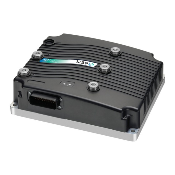
Model 1239E & 1269E
Enhanced Dual Voltage AC Controller
for PMAC and Induction Motors
» Software Version OS 37.0 «
Read Instructions Carefully!
Specifications are subject to change without notice.
© 2021 Curtis Instruments, Inc. ® Curtis is a registered trademark of Curtis Instruments, Inc.
© The design and appearance of the products depicted herein are the copyright of Curtis Instruments, Inc.
Curtis Instruments, Inc.
200 Kisco Avenue
Mt. Kisco, NY 10549
www.curtisinstruments.com
53095, Rev A, May 2021
Advertisement
Table of Contents
Troubleshooting

Related Manuals for Curtis 1239E


Summary of Contents for Curtis 1239E
- Page 1 Specifications are subject to change without notice. © 2021 Curtis Instruments, Inc. ® Curtis is a registered trademark of Curtis Instruments, Inc. © The design and appearance of the products depicted herein are the copyright of Curtis Instruments, Inc. 53095, Rev A, May 2021...
-
Page 2: Table Of Contents
TABLE OF CONTENTS 1: INTRODUCTION ..........................1 GETTING THE MOST OUT OF THE CURTIS CONTROLLER ..............3 2: INSTALLATION AND WIRING ......................4 MOUNTING THE CONTROLLER ...................... 4 HIGH POWER CONNECTIONS ......................6 LOW POWER 35-PIN CONNECTIONS ..................... 8 CONTROLLER WIRING: BASIC CONFIGURATION ................11 SWITCH INPUT WIRING ........................ - Page 3 TABLE 4: MONITOR MENU: 1313/1314 PROGRAMMER ..............76 TABLE 5: TYPES OF LED DISPLAY ...................... 138 TABLE 6: TROUBLESHOOTING CHART ....................141 TABLE D-1: SPECIFICATIONS: 1239E CONTROLLER MODELS ............155 pg. iii Curtis 1239E-1269E Manual, os 37.0 RevA – May 2021...
- Page 4 TABLE OF CONTENTS cont’d FIGURES FIGURE 1: CURTIS 1239E DUAL-VOLTAGE AC INDUCTION MOTOR CONTROLLER........1 FIGURE 2: CURTIS 1269E DUAL-VOLTAGE AC INDUCTION MOTOR CONTROLLER........2 FIGURE 3: 1239E MOUNTING DIMENSIONS ..................4 FIGURE 4: 1269E MOUNTING DIMENSIONS ..................5 FIGURE 5: BASIC WIRING DIAGRAM, CURTIS 1239E MOTOR CONTROLLER .........
-
Page 5: 1: Introduction
OEM-controlled using VCL code. VCL opens new avenues of customization, product differentiation, and responsiveness to the market. The CANbus communications included in the 1239E/1269E, as well as in many other Curtis products, allow this AC induction motor controller to be part of an efficient distributed system. Inputs and outputs can be optimally shared throughout the system, minimizing wiring and creating integrated functions that often reduce the cost of the system. - Page 6 Curtis 1269E dual-voltage AC induction motor controller. The 1239E and 1269E controller offers superior control of motor-drive performance and ease of integration into on-road vehicles. Features include: • Closed-loop speed and torque control for induction (ACIM) motors. • Full field-weakening capability with ACIM motors.
-
Page 7: Getting The Most Out Of The Curtis Controller
This manual describes the typical usage of the controller. If the intended application is not illustrated or discussed within this manual, contact the Curtis distributor or the regional Curtis sales-support office for additional technical support. The Curtis sales and support office-contact information is available from the Curtis Instruments website under the International tab. -
Page 8: 2: Installation And Wiring
2 — INSTALLATION AND WIRING MOUNTING THE CONTROLLER The outline and mounting hole dimensions for the 1239E controller are shown in Figure 3. Figure 4 is the 1269E. When an Ampseal plug housing is mated with the 35-pin logic receptacle, these controllers meet the IP65 requirements for environmental protection against dust and water. - Page 9 Curtis 1239E-1269E Manual, os 37.0 RevA – May 2021 Return to TOC Figure 4 2X 15.0 206.90 Mounting dimensions in millimeters (mm) for the Curtis 1269E 11.0 motor controller. 2X 13.5 328.50 18.3 R10 TYP 19.0 Take the required steps during the design and development of the end product to ensure that its EMC performance complies with applicable regulations;...
-
Page 10: High Power Connections
R, Y, B corresponding to the 1239E’s U, V, and W (see Table 1). Lug Assembly Five M8 terminals are provided on the 1239E models. Lugs should be installed as follows, using M8 bolts sized to provide proper engagement (see diagram): •... - Page 11 Curtis 1239E-1269E Manual, os 37.0 RevA – May 2021 Return to TOC • If two lugs are used on the same terminal, stack them so the lug carrying the least current is on top. • Tighten the assembly to 9.6 ± 0.9 N·m (85 ± 8 in-lbs).
-
Page 12: Low Power 35-Pin Connections
Curtis 1239E-1269E Manual, os 37.0 RevA – May 2021 Return to TOC LOW POWER 35-PIN CONNECTIONS The low power circuit is electrically isolated internally from the high power circuit. All low power connections are made through a single 35-pin AMPSEAL connector. The mating plug housing is AMP p/n 776164-1 and the gold-plated socket terminals are AMP p/n 770520-3 (Strip form) and 770854-3 (loose piece). -
Page 13: Table 2 Low Power Connections
Curtis 1239E-1269E Manual, os 37.0 RevA – May 2021 Return to TOC Table 2 Low Power Connections Related VCL* Name Description Function References Keyswitch input. Provides logic power Keyswitch_Voltage for the controller and power for the coil drivers. Automate_PWM() Sw_13 Proportional driver. - Page 14 Curtis 1239E-1269E Manual, os 37.0 RevA – May 2021 Return to TOC Table 2 Low Power Connections, cont’d Related VCL* Name Description Function References Setup_Pot() Throttle_Pot Throttle Pot Wiper Pot wiper connection for the throttle pot. Setup_Pot_Faults() Throttle_Pot_Output Setup_Pot() Brake_Pot Pot2 Wiper Pot wiper connection for the brake pot.
-
Page 15: Controller Wiring: Basic Configuration
EEC safety requirements. The internal capacitor precharge function is performed with an external relay and precharge resistor. No internal precharge feature is provided in the 1239E/1269E controllers. Precharge decreases main contactor arcing and can increase the contactor’s life. - Page 16 Curtis 1239E-1269E Manual, os 37.0 RevA – May 2021 Return to TOC J1-1 J1-13 J1-24 COIL RETURN SWITCH 1 / ANALOG 1 MAIN J1-9 INTERLOCK KEYSWITCH SWITCH 3 J1-6 DRIVER 1 J1-10 SWITCH 4 BRAKE J1-5 DRIVER 2 J1-11 SWITCH 5...
- Page 17 Curtis 1239E-1269E Manual, os 37.0 RevA – May 2021 Return to TOC J1-1 J1-24 SWITCH 1 / ANALOG 1 J1-13 INTERLOCK J1-9 COIL RETURN SWITCH 3 MAIN KEYSWITCH J1-10 SWITCH 4 J1-6 DRIVER 1 J1-11 SWITCH 5 BRAKE E-STOP J1-5...
-
Page 18: Switch Input Wiring
Curtis 1239E-1269E Manual, os 37.0 RevA – May 2021 Return to TOC SWITCH INPUT WIRING The following inputs are dedicated to specific functions when the parameter settings are as shown: Switch 3: Interlock input if Interlock Type = 0 Switch 7: Forward input if Throttle Type = 1–3 Switch 8: Reverse input if Throttle Type = 1–3... - Page 19 Curtis 1239E-1269E Manual, os 37.0 RevA – May 2021 Return to TOC LOW POWER GROUND SPECIFICATIONS Output Name Output Current Protected Voltage ESD Tolerance Voltage Low Power 13A max ± 8 kV (air Not Protected Ground continuous discharge) Digital Inputs These control lines can be used as digital (on/off ) inputs.
- Page 20 Curtis 1239E-1269E Manual, os 37.0 RevA – May 2021 Return to TOC DIGITAL INPUT IMPEDANCE CIRCUITS 5V clamp 3.3V clamp 5V clamp Supervisor µP DRIVER INPUTS 150 kΩ SWITCH INPUTS (pins 6, 5, 4, 3, 2) Primary 1-8, 16 µP µP...
- Page 21 Curtis 1239E-1269E Manual, os 37.0 RevA – May 2021 Return to TOC Analog Inputs Two control lines can be used as analog inputs. Both inputs are protected against shorts to KSI or low power ground. Typically Analog 2 is used as the input for the motor temperature sensor. This input provides a constant current appropriate for a thermistor sensor.
- Page 22 Curtis 1239E-1269E Manual, os 37.0 RevA – May 2021 Return to TOC KSI and Coil Return The KSI input provides positive voltage for the low power control circuit. This includes the microprocessors, power supply outputs, and power for the digital and PWM outputs.
- Page 23 28 and 29, along with ground (pin 7) and the +12V power supply (pin 25); see wiring diagram, Figure 5. The Curtis “Spy” Model 840 display will connect the serial-port pins as shown in Figures 5 and 6).
- Page 24 Curtis 1239E-1269E Manual, os 37.0 RevA – May 2021 Return to TOC Position Feedback Input: Quadrature Encoder Two control lines are internally configured to read a quadrature type position encoder. The encoder is typically powered from the 5V supply (pin 26) or 12V supply (pin 25), but can be powered from any external supply (from 5V up to B+) as long as the logic threshold and differential voltage requirements are met.
- Page 25 Curtis 1239E-1269E Manual, os 37.0 RevA – May 2021 Return to TOC Sine/Cosine Signal Tracking The values of the inputs are tracked to ensure an accurate position can be obtained if the signal amplitude changes during operation. The amplitude of the signal may alter due to mechanical tolerances, thermal expansion, magnetic field strength changes in the actuator magnet etc.
-
Page 26: 3: Application-Specific Features
(2) as a generic term covering both the drive throttle and the brake throttle. Wiring is the same, whether the throttle in question is used for acceleration or (regen) braking. Various throttles can be used with the 1239E/1269E controller. They are characterized as one of five types in the parameters menu of the 1313/1314 programmer. - Page 27 Hall‑effect voltage throttles: The Curtis FP Series of throttles offers multiple pedal angles and mounting configurations (floor, suspended, flush) with 0-5 Volt operation with a Idle Validation Switch (IVS). The ET-XXX electronic throttle is typically used only as a drive throttle (illustrated in Fig.
- Page 28 Curtis 1239E-1269E Manual, os 37.0 RevA – May 2021 Return to TOC Figure 8 Voltage Source Wiring for Type 2 throttles. Sensor-referenced 0–5V source Ground-referenced 0–5V source Pot Wiper input (Pin 16 or 17) Pot Wiper input (Pin 16 or 17) SENSOR OUTPUT (0–5V)
- Page 29 Note: The option also applies to the Brake Type, which when set to Type 5 uses VCL_Brake as signal chain for the Brake_Command (see the Brake parameter menu and Figure 18). For questions regarding this throttle type, contact the Curtis distributor or support engineer. 3 — APPLICATION-SPECIFIC FEATURES...
-
Page 30: Motor Speed Constraints
* This maximum allowed speed is displayed in the Monitor » Motor » Max Speed Controller Limit variable Note: In the case where the Max Speed parameter is the prevailing constraint, greater RPM may be possible. Contact the Curtis distributor or support engineer to discuss the application. pg. 26... -
Page 31: Voltage Limits
Curtis 1239E-1269E Manual, os 37.0 RevA – May 2021 Return to TOC VOLTAGE LIMITS High Power Circuit For the high power circuit, overvoltage protection cuts back regen braking to prevent damage to batteries and other electrical system components due to high B+ voltage. Undervoltage protection prevents systems from operating at voltages below their design thresholds. -
Page 32: Battery Discharge Indicator
Note that the 12V low power circuit ground must be connected to the vehicle chassis for the isolation monitor to function properly. Also note that only one isolation monitor should be enabled on a given vehicle. The accuracy of the Curtis 1239E/1269E insulation resistance measurement is ±10% of full scale, from 6 kΩ to 500 kΩ. -
Page 33: 4: Programmable Parameters
Return to TOC 4 — PROGRAMMABLE PARAMETERS These controllers have a number of parameters that can be programmed using a Curtis 1313 handheld programmer or 1314 PC Programming Station. The programmable parameters allow the vehicle’s performance to be customized to fit the needs of specific applications. -
Page 34: Table 3 Programmable Parameters Menus: 1313/1314 Programmer
Curtis 1239E-1269E Manual, os 37.0 RevA – May 2021 Return to TOC Table 3 Programmable Parameters Menus: 1313/1314 Programmer CONTROL MODE SELECT....p. 35 CURRENT LIMITS MENU....— RESTRAINT......p. 40 p. 46 — Restraint Forward — Drive Current Limit 0 - SPEED MODE EXPRESS..... - Page 35 Curtis 1239E-1269E Manual, os 37.0 RevA – May 2021 Return to TOC Table 3 Programmable Parameters Menus: 1313/1314 Programmer continued — Max Test Speed EM BRAKE CONTROL MENU..p. 52 — FAULT CHECKING......p. 56 — Motor Type — Brake Type —...
- Page 36 Curtis 1239E-1269E Manual, os 37.0 RevA – May 2021 Return to TOC Table 3 Programmable Parameters Menus: 1313/1314 Programmer continued BATTERY CURRENT LIMITING MENU..p. 71 INTERLOCK BRAKING MENU..p. 73 — Sin Max — Battery Current Limiter Enable — Enable —...
- Page 37 Curtis 1239E-1269E Manual, os 37.0 RevA – May 2021 Return to TOC Individual parameters are presented as follows in the menu charts: Parameter name as it appears in the programmer display. Motor Technology 0 – 1 Set this parameter to the type of motor in the vehicle:...
- Page 38 Curtis 1239E-1269E Manual, os 37.0 RevA – May 2021 Return to TOC CAN SDO and PDO message transmission nomenclature: With regard to SDO messages, the terms “Client”, “Server”, ”Request”, and “Response” are used. For SDOs, the Client /Server are: – Used in SDO transfers, including data uploads and downloads.
- Page 39 1 = SPEED MODE 2 = TORQUE MODE Contact the Curtis distributor or support engineer if there is interest in a non-generic control method. Note: Such a case will almost always require time, which may delay any immediate project’s time-frame over the standard options.
- Page 40 Curtis 1239E-1269E Manual, os 37.0 RevA – May 2021 Return to TOC 1 - SPEED MODE — SPEED CONTROLLER MENU PARAMETER ALLOWABLE RANGE DESCRIPTION Max Speed 100 – 10000 rpm Defines the maximum requested motor rpm at full throttle. Partially-applied Max_Speed_SpdM throttle is scaled proportionately;...
- Page 41 Curtis 1239E-1269E Manual, os 37.0 RevA – May 2021 Return to TOC 1 - SPEED MODE — VELOCITY FEEDFORWARD MENU [OPTIONAL] PARAMETER ALLOWABLE RANGE DESCRIPTION Kvff 0 – 500 A This velocity feedforward term is designed to improve throttle responsiveness and speed controller performance, especially at low speeds.
- Page 42 Curtis 1239E-1269E Manual, os 37.0 RevA – May 2021 Return to TOC 1 - SPEED MODE — RESPONSE MENU PARAMETER ALLOWABLE RANGE DESCRIPTION Full Accel Rate HS 0.1 – 30.0 s Sets the rate (in seconds) at which the speed command increases when full throttle is applied at high vehicle speeds.
- Page 43 Curtis 1239E-1269E Manual, os 37.0 RevA – May 2021 Return to TOC 1 - SPEED MODE — FINE TUNING MENU PARAMETER ALLOWABLE RANGE DESCRIPTION Partial Decel Rate 0.1 – 30.0 s Sets the rate (in seconds) that is used to slow down the vehicle when the Partial_Decel_Rate_SpdM throttle is reduced without being released to neutral.
- Page 44 Curtis 1239E-1269E Manual, os 37.0 RevA – May 2021 Return to TOC 1 - SPEED MODE — RESTRAINT MENU PARAMETER ALLOWABLE RANGE DESCRIPTION Restraint Forward 0 – 100% Increases torque when on a steep hill in order to limit roll-forward speed.
- Page 45 Curtis 1239E-1269E Manual, os 37.0 RevA – May 2021 Return to TOC 1 - SPEED MODE — POSITION HOLD MENU PARAMETER ALLOWABLE DESCRIPTION RANGE Position Hold Enable On / Off Allows the Position Hold mode to be entered at zero throttle when the vehicle comes to |Position_Hold_Enable a stop.
- Page 46 Curtis 1239E-1269E Manual, os 37.0 RevA – May 2021 Return to TOC 2 - TORQUE MODE — SPEED LIMITER MENU PARAMETER ALLOWABLE RANGE DESCRIPTION Max Speed 500 – 10000 rpm Defines the maximum allowed motor rpm for torque control mode Max_Speed_TrqM (independent of throttle position).
- Page 47 Curtis 1239E-1269E Manual, os 37.0 RevA – May 2021 Return to TOC 2 - TORQUE MODE — RESPONSE MENU PARAMETER ALLOWABLE RANGE DESCRIPTION Accel Rate 0.1 – 30.0 s Sets the rate (in seconds) at which the motor torque increases to full when Accel_Rate_TrqM full throttle is applied.
- Page 48 Curtis 1239E-1269E Manual, os 37.0 RevA – May 2021 Return to TOC 2 - TORQUE MODE — FINE TUNING MENU PARAMETER ALLOWABLE RANGE DESCRIPTION Creep Torque 0 – 100% Determines the amount of torque applied to the vehicle at a stop with no Creep_Torque_TrqM throttle input, to emulate the feel of an automatic transmission automobile;...
- Page 49 Curtis 1239E-1269E Manual, os 37.0 RevA – May 2021 Return to TOC CURRENT + Throttle=100% Curve Regen Current Limit Drive Current Limit Creep Torque Throttle=0% Curve MOTOR MOTOR RPM - RPM + Forward/Back Neutral Taper Speed Full Restraint Speed Neutral Braking x Regen Current Limit...
- Page 50 Curtis 1239E-1269E Manual, os 37.0 RevA – May 2021 Return to TOC CURRENT LIMITS MENU PARAMETER ALLOWABLE RANGE DESCRIPTION Drive Current Limit 5 – 100% Sets the maximum RMS current the controller will supply to the motor Drive_Current_Limit during drive operation, as a percentage of the controller’s full rated current.* 1638 –...
- Page 51 Curtis 1239E-1269E Manual, os 37.0 RevA – May 2021 Return to TOC DRIVE LIMITING MAP MENU PARAMETER ALLOWABLE RANGE DESCRIPTION Nominal 0 – 100% PL_Drive_Nominal 0 – 32767 0x3060 0x00 Plus Delta 0 – 100% These parameters define the percentage of drive current limit that PL_Drive_Nominal_Plus_Delta 0 –...
- Page 52 Curtis 1239E-1269E Manual, os 37.0 RevA – May 2021 Return to TOC REGEN LIMITING MAP MENU PARAMETER ALLOWABLE RANGE DESCRIPTION Nominal 0 – 100% PL_Regen_Nominal 0 – 32767 0x3065 0x00 Plus Delta 0 – 100% PL_Regen_Nominal_Plus_Delta 0 – 32767 These parameters define the percentage of regen current limit or...
- Page 53 Curtis 1239E-1269E Manual, os 37.0 RevA – May 2021 Return to TOC THROTTLE MENU PARAMETER ALLOWABLE RANGE DESCRIPTION Throttle Type 1 – 5 These E and SE controllers accept a variety of throttle inputs. The throttle type Throttle_Type parameter can be programmed as follows: 1 –...
- Page 54 Curtis 1239E-1269E Manual, os 37.0 RevA – May 2021 Return to TOC THROTTLE MENU, cont’d PARAMETER ALLOWABLE RANGE DESCRIPTION HPD SRO Type 0 – 3 Determines the type of HPD (High Pedal Disable) / SRO (Static Return to Off) HPD_SRO_Type protection.
- Page 55 Curtis 1239E-1269E Manual, os 37.0 RevA – May 2021 Return to TOC BRAKE MENU PARAMETER ALLOWABLE RANGE DESCRIPTION Brake Pedal Enable On / Off Determines whether the brake input and algorithm are enabled, making the |Brake_Pedal_Enable brake throttle part of the motor control command.
- Page 56 Curtis 1239E-1269E Manual, os 37.0 RevA – May 2021 Return to TOC EM BRAKE CONTROL MENU PARAMETER ALLOWABLE DESCRIPTION RANGE Brake Type 0 – 2 This Brake Type parameter determines how the EM brake responds to EM_Brake_Type the interlock input, throttle, and vehicle motor speed.
- Page 57 Curtis 1239E-1269E Manual, os 37.0 RevA – May 2021 Return to TOC EM BRAKE CONTROL MENU, cont’d PARAMETER ALLOWABLE DESCRIPTION RANGE Position Hold Settling Time 0 – 5000 ms Determines how long the position hold function is allowed to operate Position_Hold_Settling_Time before the EM brake is set.
- Page 58 Curtis 1239E-1269E Manual, os 37.0 RevA – May 2021 Return to TOC EM BRAKE CONTROL: EM BRAKE TEST MENU PARAMETER ALLOWABLE DESCRIPTION RANGE Mode 0 – 1 Controls the test mode for the EM brake. EM_Brake_Test_Mode 0 – 1 0=VCL...
- Page 59 Curtis 1239E-1269E Manual, os 37.0 RevA – May 2021 Return to TOC DRIVERS: MAIN CONTACTOR MENU, cont’d PARAMETER ALLOWABLE DESCRIPTION RANGE Holding Voltage 0 – 100% The main contactor holding voltage parameter allows a Main_Holding_Voltage reduced average voltage to be applied to the contactor coil 0 –...
- Page 60 Curtis 1239E-1269E Manual, os 37.0 RevA – May 2021 Return to TOC DRIVERS: DRIVER 3 MENU PARAMETER ALLOWABLE RANGE DESCRIPTION Pull In Voltage 0 – 100% The pull-in voltage parameter allows a high initial voltage when the contactor Driver3_Pull_In_Voltage driver first turns on, to ensure contactor closure. After 1 second, this peak 0 –...
- Page 61 PMAC Support NOTICE All existing 1239E models and the 1269E support PMAC operation with OS 37.0, but the OEM must insure that KSI power is active any time the motor is moving. Removal of KSI power when the motor is spinning past the base speed may result in immediate controller damage.
- Page 62 If a new (or existing Type 0) motor is auto-characterized following the steps in Chapter 8A, do not use this parameter, as it is automatically included in the full auto-characterization routine. Consult the Curtis distributor or support engineer for further assistance based on the motor and its application. Quick Link: Chapter 8A (ACIM motor characterization) p.92...
- Page 63 The maximum setting of the Field Weakening Drive parameter depends on the type of motor characterization that was used. If the ACIM motor was dyno characterized (i.e., sent to the Curtis factory for characterization on the motor dyno), Field Weakening Drive can be set anywhere in the range of 0% (lowest torque, highest efficiency) to 100% (highest torque, lowest efficiency).
- Page 64 Speed parameter. Other parameters may also need to be reset or evaluated by following the Initial Setup and Tuning Guide chapters instructions. Consult the Curtis distributor or support engineer for information how to set this parameter based on the application and motor.
- Page 65 Curtis 1239E-1269E Manual, os 37.0 RevA – May 2021 Return to TOC MOTOR: LOS (Limited Operating Strategy) MENU PARAMETER ALLOWABLE DESCRIPTION RANGE LOS Upon Encoder Fault On / Off Limited Operating Strategy (LOS) is typically used to drive the vehicle back to |LOS_Upon_Encoder_Fault a repair center at very low speeds in the event the motor encoder fails.
- Page 66 Curtis 1239E-1269E Manual, os 37.0 RevA – May 2021 Return to TOC MOTOR: 1 – PMAC (PERMANENT MAGENT MOTOR): COMMISSIONING TESTS MENU PARAMETER ALLOWABLE RANGE DESCRIPTION Typical Max Speed 500 – 10000 RPM Set this parameter to the typical maximum motor speed of the vehicle.
- Page 67 Curtis 1239E-1269E Manual, os 37.0 RevA – May 2021 Return to TOC MOTOR: 1 – PMAC (PERMANENT MAGENT MOTOR): FIELD WEAKENING CONTROL MENU PARAMETER ALLOWABLE RANGE DESCRIPTION Field Weakening Rate 0 – 100 % Sets the control loop gains for field weakening. Setting the rate too PMAC_Field_Weakening_Rate 0 –...
- Page 68 Curtis 1239E-1269E Manual, os 37.0 RevA – May 2021 Return to TOC MOTOR: 1 – PMAC (PERMANENT MAGENT MOTOR): COMMISSIONING RESULTS MENU PARAMETER ALLOWABLE RANGE DESCRIPTION Tuning Voltage 22.0 – 200.0V This value is set by the commissioning process and indicates the PMAC_Tuning_Nominal_Pack_Voltage 1408 –...
- Page 69 Curtis 1239E-1269E Manual, os 37.0 RevA – May 2021 Return to TOC MOTOR: FEEDBACK OPTIONS MENU PARAMETER ALLOWABLE RANGE DESCRIPTION Feedback Type 1 – 2 Set this parameter to the type of position feedback device in the vehicle: Feedback_Type 1 – 2 1 = quadrature encoder.
- Page 70 Curtis 1239E-1269E Manual, os 37.0 RevA – May 2021 Return to TOC MOTOR: FEEDBACK OPTIONS – 2 – SIN/COS MENU PARAMETER ALLOWABLE RANGE DESCRIPTION Enable Multiturn Sensor 0 – 1 Indicates whether the encoder is 1 revolution per electrical cycle (= 0) Feedback_Multiturn 0 –...
- Page 71 Curtis 1239E-1269E Manual, os 37.0 RevA – May 2021 Return to TOC MOTOR: FEEDBACK OPTIONS – FEEDBACK FAULT SETUP PARAMETER ALLOWABLE RANGE DESCRIPTION Fault Detection Enable On/Off When programmed On, encoder fault checking is enabled. Three fault |Encoder_Fault_Detection_Enable On/Off conditions are checked: Encoder Fault (fault code 36, Stall Detected |Encoder_Fault_Detection_Enable_Bit0 [Bit 0] (fault code 73), and Encoder Pulse Error (fault code 88).
- Page 72 Curtis 1239E-1269E Manual, os 37.0 RevA – May 2021 Return to TOC MOTOR: TEMPERATURE CONTROL MENU PARAMETER ALLOWABLE DESCRIPTION RANGE Sensor Enable On / Off When programmed On, the motor temperature cutback and the motor |MotorTemp_Sensor_Enable temperature compensation features are enabled. This parameter can...
- Page 73 Curtis 1239E-1269E Manual, os 37.0 RevA – May 2021 Return to TOC BATTERY MENU PARAMETER ALLOWABLE RANGE DESCRIPTION Nominal Voltage 60 – 144 V Must be set to the vehicle’s nominal battery pack voltage. This parameter Nominal_Voltage is used in determining the overvoltage and undervoltage protection 3840 –...
- Page 74 Curtis 1239E-1269E Manual, os 37.0 RevA – May 2021 Return to TOC BATTERY MENU, cont’d PARAMETER ALLOWABLE RANGE DESCRIPTION Reset Volts Per Cell 0.900 – 3.000 V The reset voltage level is checked only once, when the main contactor BDI_Reset_Volts_Per_Cell first closes.
- Page 75 Curtis 1239E-1269E Manual, os 37.0 RevA – May 2021 Return to TOC BATTERY: BATTERY CURRENT LIMITING PARAMETER ALLOWABLE RANGE DESCRIPTION Battery Current Limiter Enable 0 – 1 Setting this parameter to 1 enables drive and regen battery current Battery_Current_Limiter_Enable 0 – 1 limits.
- Page 76 Curtis 1239E-1269E Manual, os 37.0 RevA – May 2021 Return to TOC BATTERY: BATTERY POWER LIMITING PARAMETER ALLOWABLE RANGE DESCRIPTION Drive Power Limit 0.00 – 300.00 kW Sets a limit on the DC power that the controller will draw out of Battery_Drive_Power_Limit 0 –...
- Page 77 Curtis 1239E-1269E Manual, os 37.0 RevA – May 2021 Return to TOC INTERLOCK BRAKING MENU PARAMETER ALLOWABLE RANGE DESCRIPTION Enable On / Off Determines whether the interlock braking function is active. |Interlock_Brake_Enable On / Off On = The controller will attempt to bring the vehicle to a stop using regen |OptionBits3 [Bit 7] braking when the interlock signal is removed.
- Page 78 CAN( ) function). Beginning with OS 32.0, eight new CAN mailboxes were added for use by VCL. The total is now 32. See the System Information file (available from within the Curtis WinVCL program, Info tab). pg. 74 4 — PROGRAMMABLE PARAMETERS...
-
Page 79: Cloning Controllers
Save the parameters from the controller to clone, which is the act of saving a “.CPF” file (Curtis Program File) using the Save/Save As . . . operations. When saving the CPF file, chose a file name with meaning as this CPF file is used to write (clone) its data to subsequent controllers. -
Page 80: 5: Monitor Menu
Curtis 1239E-1269E Manual, os 37.0 RevA – May 2021 Return to TOC 5 — MONITOR MENU Through its Monitor menu, the 1313 handheld and 1314 PC programmers provide access to real-time data during vehicle operation. This information is helpful during diagnostics and troubleshooting, and also while adjusting programmable parameters and the vehicle’s initial setup. - Page 81 Curtis 1239E-1269E Manual, os 37.0 RevA – May 2021 Return to TOC Monitor Menu: INPUTS VARIABLE DISPLAY RANGE DESCRIPTION Throttle Command –100.0 – 100.0% Throttle request to slew rate block. Throttle_Command –32767 – 32767 0x3216 0x00 Throttle Multiplier –200.0 – 200.0% Multiplies or divides the throttle signal;...
- Page 82 Curtis 1239E-1269E Manual, os 37.0 RevA – May 2021 Return to TOC Monitor Menu: INPUTS, cont’d VARIABLE DISPLAY RANGE DESCRIPTION Switch 5 On / Off Switch 5 on or off (pin 11). |Sw_5 On / Off |Switches [Bit 4] 0x3226 0x00...
- Page 83 Curtis 1239E-1269E Manual, os 37.0 RevA – May 2021 Return to TOC Monitor Menu: OUTPUTS VARIABLE DISPLAY RANGE DESCRIPTION Analog Out 0.00 – 10.00 V Voltage at Analog output (pin 30). Analog_Output 0 – 32767 0x321D 0x00 Digital Out 6 On / Off Digital Out 6 output on or off (pin 19).
- Page 84 Curtis 1239E-1269E Manual, os 37.0 RevA – May 2021 Return to TOC Monitor Menu: BATTERY VARIABLE DISPLAY RANGE DESCRIPTION 0 – 100% Lead-acid battery discharge indicator (BDI). Effectively the battery’s BDI_Percentage remaining state-of-charge. 0 – 100 NOTE: For non lead-acid batteries, including Lithium-Ion battery packs, use 0x3308 0x00 the pack’s or cell manufacturer’s approved Battery Management System...
- Page 85 Curtis 1239E-1269E Manual, os 37.0 RevA – May 2021 Return to TOC Monitor Menu: CONTROLLER VARIABLE DISPLAY RANGE DESCRIPTION Current (RMS) 0.0 – 1000.0 A RMS current of the controller, taking all three phases into account. Current_RMS 0 – 10000...
- Page 86 Curtis 1239E-1269E Manual, os 37.0 RevA – May 2021 Return to TOC Monitor Menu: CONTROLLER, cont’d VARIABLE DISPLAY RANGE DESCRIPTION PMAC Commissioning Status 0 – 8 0 - Motor Needs Commissioning. PMAC_Commissioning_State_ 0 – 8 1 - Commissioning Not Started.
- Page 87 Curtis 1239E-1269E Manual, os 37.0 RevA – May 2021 Return to TOC Monitor Menu: CONTROLLER, cont’d VARIABLE DISPLAY RANGE DESCRIPTION Supervision Error 0 – 4 A Supervision Fault (fault code 77) will store additional information in the Supervision_Error Supervision Error variable: 0 –...
- Page 88 Curtis 1239E-1269E Manual, os 37.0 RevA – May 2021 Return to TOC Monitor Menu: VEHICLE VARIABLE DISPLAY RANGE DESCRIPTION Vehicle Speed –3276.8 – 3276.7 Vehicle speed, in units of MPH or KPH, depending on the setting of the Metric Vehicle_Speed Units parameter (see Program »...
- Page 89 Curtis 1239E-1269E Manual, os 37.0 RevA – May 2021 Return to TOC Monitor Menu: CAN STATUS VARIABLE DISPLAY RANGE DESCRIPTION CAN Node ID 0 – 127 Displays the controller’s Node ID. CAN_Node_ID 0 – 127 0x3145 0x00 CAN NMT State 0 –...
-
Page 90: 6: Controller Information Menu
0 – 4294967295 0x1018 0x04 Model Number 0 – 4294967295 Model number. For example, for a 1239E controller with the model number 1239E- Model Number 8521, the Model Number variable will have a value of 12398521. 0 – 4294967295 0x3464 0x00 Mfg Date Code 0 –... -
Page 91: 7: Initial Setup
Motors in the Curtis database are assigned a number, which is the number used for the ACIM Motor Type parameter. • Send the ACIM motor to Curtis for testing on the factory motor dyno. The motor’s data will be entered into the Curtis database and issue updated software (OS) with the appropriate parameter values set to match the motor. - Page 92 Curtis 1239E-1269E Manual, os 37.0 RevA – May 2021 Return to TOC PMAC: For PMAC motor applications, start these initial setup procedures now. The PMAC motor commissioning will be preformed after completing steps 1 through 9. Then finish this Chapter’s Initial Steps prior to completing the fine-tuning in Chapter 9.
- Page 93 = –100% through the range considered maximum reverse throttle. Contact the Curtis distributor or support engineer to resolve any issues about the throttle setup before continuing with the initial setup procedures. Step 7: Brake...
- Page 94 All faults and errors (including those in the History file) must be cleared before continuing with the initial setup. Use Chapter 10 for help in troubleshooting. Contact the Curtis customer support engineer to resolve any fault issues before continuing with the setup procedure.
- Page 95 (a) Already have software with the motor data programmed to match the motor. The pre-set motor data software is usually the result of contacting Curtis and getting a match between the motor and the Curtis ACIM motor database, or by shipping a motor to the Curtis factory for dyno characterization.
- Page 96 Curtis 1239E-1269E Manual, os 37.0 RevA – May 2021 Return to TOC For vehicle development purposes, to simulate the measurement or fault threshold of an external insulation fault, connect a known resistance between the vehicle chassis and the high power battery (positive or negative).
-
Page 97: Automated Acim Motor Characterization Procedure
Curtis 1239E-1269E Manual, os 37.0 RevA – May 2021 Return to TOC 8A — AUTOMATED ACIM MOTOR CHARACTERIZATION PROCEDURE WARNING Motor will rotate during this procedure. Do not take the vehicle down off the blocks. This procedure is only for applications using an ACIM motor and quadrature encoder. - Page 98 Error and reference the following table. All errors except “1” indicate the motor characterization data is invalid. For error “1, ” the data is valid but Encoder Steps must be set manually. Contact the Curtis distributor or support engineer if the Motor Characterization Errors indicated cannot be resolved.
- Page 99 Speed Mode Express: Accel Rate. Speed Mode: Full Accel LS, Full Accel HS, Low Accel. Torque Mode: Accel Rate. (this is the typical 1239E/1269E usage) On the 1313 programmer, add these two items to the Favorites shortcut, to easily toggle between them: Monitor »...
- Page 100 Note: the present Field Weakening Drive value (0%) was determined by the above auto- characterization routine, and is not the default value (100%) in the native OS intended for the Curtis dynamometer characterized motors when a motor type (number) is utilized. The differences are: Auto Characterized: Field Weakening Drive is adjusted UP from 0% to the max Field Weakening Drive determined in this text.
-
Page 101: Automated Pmac Motor Commissioning Procedure
COMMISSIONING PROCEDURE PMAC CONSIDERATIONS All existing 1239E models and the 1269E support PMAC operation with OS 37.0, but the OEM must insure that KSI power is active any time the motor is moving. Removal of KSI power when the motor is spinning past the base speed may result in immediate controller damage. - Page 102 Monitor » Controller » Motor Characterization Error and reference the following table. An error during the PMAC commissioning test indicates the motor commissioning data is invalid; contact the Curtis distributor or support engineer for assistance if the indicated error cannot be resolved.
- Page 103 Curtis 1239E-1269E Manual, os 37.0 RevA – May 2021 Return to TOC Motor Characterization Errors Sequencing error. Normally caused by turning off Motor Commissioning Test. Enable before running test. Motor temperature sensor fault. Motor overtemperature > Motor Temperature Hot parameter (active only when temp sensor is present).
-
Page 104: 9: Tuning Guide
Curtis 1239E-1269E Manual, os 37.0 RevA – May 2021 Return to TOC 9 — TUNING GUIDE Many aspects of vehicle performance can be optimized, using the wide variety of adjustable parameters available to the controller. Once a vehicle/motor/ controller combination has been tuned, the parameter values can be made standard for the system or vehicle model. - Page 105 Curtis 1239E-1269E Manual, os 37.0 RevA – May 2021 Return to TOC 1 − Speed Mode Tuning 1.1 Adjust Max Speed to the maximum speed the motor should turn in the vehicle application; this speed setting corresponds to an input of full throttle.
- Page 106 Curtis 1239E-1269E Manual, os 37.0 RevA – May 2021 Return to TOC 1.4 In the Speed Mode » Response menu, adjust the five Accel and Decel Rate parameters as Quick Links: Speed Mode menu p.36 necessary while moving the throttle to different positions (i.e., neutral to full throttle, half throttle Response menu p.38...
-
Page 107: 10: Vehicle Control Language (Vcl)
This chapter of the manual summarizes VCL and also describes aspects and functions of VCL that are specific to the 1239E/1269E controller. For a more complete understanding of the functions and capabilities of VCL, see the WinVCL User’s Guide, VCL Programmer’s Guide, and VCL Common Functions Manual. -
Page 108: Variable Types
The VCL functions described in the VCL Common Functions Manual are available on the 1239E/1269E controllers. The controllers have these additional specific functions, listed below. All VCL functions, common and specific, are also available in the controller’s os37 sysInfo file. - Page 109 Curtis 1239E-1269E Manual, os 37.0 RevA – May 2021 Return to TOC Parameters EEPROM variables are a special type of EEPROM variable that is intended to be used to create OEM defined 1313/1314 programmer parameters. These parameters can be defined as 16- bit by using the P_User variables or they can be defined as bit (On/Off ) by using the P_User_Bit variables.
-
Page 110: Vcl Runtime Rates
Curtis 1239E-1269E Manual, os 37.0 RevA – May 2021 Return to TOC VCL RUNTIME RATES VCL is an interpreted language. Each line of VCL code is converted (compiled) into a set of codes and then flash loaded into the controller. The controller interprets these codes one line at a time while the system is powered up. -
Page 111: I/O Control With Vcl
Curtis 1239E-1269E Manual, os 37.0 RevA – May 2021 Return to TOC I/O CONTROL WITH VCL Digital Inputs The controllers each have 16 digital inputs. Nine are switch inputs (Sw_1 through Sw_8, and Sw_16. These switch inputs are shown on the standard wiring diagram (Figure 5, page 12). - Page 112 Curtis 1239E-1269E Manual, os 37.0 RevA – May 2021 Return to TOC The proportional driver (Driver 5, Pin 2) is different from Drivers 1–4. It can be controlled in two ways: with the proportional driver processing function (see Figure 20) or with the VCL Put_PWM() function.
-
Page 113: Interfacing The Throttle And Brake Commands
Curtis 1239E-1269E Manual, os 37.0 RevA – May 2021 Return to TOC The 0–100% position of the potentiometer is represented by a value from 0–32767 in VCL, and is set up through the VCL Setup_Pot() function. It is important to use the correct setup (ONE_WIRE, TWO_WIRE, or THREE_WIRE) since the input is automatically re-scaled for 0–100% based on the... - Page 114 Curtis 1239E-1269E Manual, os 37.0 RevA – May 2021 Return to TOC The throttle and brake signal chains within the controller are sophisticated and flexible. Before applying VCL to modify these chains, it is important to fully understand the ramifications of implementing changes.
- Page 115 Curtis 1239E-1269E Manual, os 37.0 RevA – May 2021 Return to TOC For investigating why a motor is not spinning, it is useful to use the 1313/1314 to check the state of the throttle signal from beginning to end: using Throttle_Pot_ Raw, Mapped_Throttle, and Throttle_ Command.
- Page 116 Curtis 1239E-1269E Manual, os 37.0 RevA – May 2021 Return to TOC pg. 112 10 — VEHICLE CONTROL LANGUAGE (VCL)
- Page 117 Automated Characterization AC Induction motors p.93 Mode there is no emergency reverse. (Note: emergency reverse is not applicable to the 1239E/1269E controller’s on-road applications). The control mode function uses algorithms to convert the incoming throttle and brake signals, the motor rpm, and associated parameter settings into a Controller Torque Command.
- Page 118 Curtis 1239E-1269E Manual, os 37.0 RevA – May 2021 Return to TOC pg. 114 10 — VEHICLE CONTROL LANGUAGE (VCL)
-
Page 119: Interfacing The Proportional Current Driver
Return to TOC INTERFACING THE PROPORTIONAL CURRENT DRIVER Note: The 1239E and 1269E applications typically do not utilize the proportional current drivers as used in material handling trucks. See the 1232E-1238E manual (53096) for the parameters. Contact Curtis to enable these parameters, which will require a different OS parameter block. - Page 120 Curtis 1239E-1269E Manual, os 37.0 RevA – May 2021 Return to TOC PD Max Current PD Dither Period PD Kp Put_PWM(PWM5,xxxx) PD Min Current PD Dither Percent PD Ki ShutdownPD Lower + %Dither PD_Output Enable = On VCL_PD_Throttle PD_Throttle PD Enable...
-
Page 121: Using The Fault Handler In Vcl
Curtis 1239E-1269E Manual, os 37.0 RevA – May 2021 Return to TOC USING THE FAULT HANDLER IN VCL The controller’s operating system detects various faults and takes appropriate fault actions to protect the controller, motor, and overall system. These faults have fault codes that are flashed on the controller status LEDs. - Page 122 Curtis 1239E-1269E Manual, os 37.0 RevA – May 2021 Return to TOC Status5 Bit0 = External Supply Out of Range (Code 69) Bit1 = Motor Temp Sensor Fault (Code 29) Bit2 = VCL Run Time Error (Code 68) Bit3 = +5V Supply Failure (Code 25)
-
Page 123: Canbus Emergency Messages
Curtis 1239E-1269E Manual, os 37.0 RevA – May 2021 Return to TOC CANbus Emergency Messages The Status1–9 faults form CAN emergency message using little-endian byte ordering, where: Byte1&2 is the Error Category, Byte3 is the error register which is “set” (01) if there is an active fault, and Bytes 4–8 map into the Status 1–9 faults as per the error category. -
Page 124: Oem-Defined User Faults
Curtis 1239E-1269E Manual, os 37.0 RevA – May 2021 Return to TOC OEM‑defined User Faults The operating system provides the capability to create OEM-defined custom faults using VCL. Just as with system faults, the VCL fault codes are flashed on the controller Status LEDs and fault text is displayed on the 1313/1314 System Faults and Fault History menus. - Page 125 Curtis 1239E-1269E Manual, os 37.0 RevA – May 2021 Return to TOC To add automatic fault actions to the VCL faults, the VCL programmer must define the desired fault actions by using the sixteen VCL variables: User_Fault_Action_01 through User_Fault_Action_16. Each of the UserFault bits has a corresponding User_Fault_Action_xx variable (where “xx” is the number of the VCL fault bit).
- Page 126 Curtis 1239E-1269E Manual, os 37.0 RevA – May 2021 Return to TOC This time when UserFault1.2 is set, the operating system will ShutdownInterlock and ShutdownThrottle (which will result in a Throttle_Command = 0%) in addition to flashing the code 52 on the controller status LEDs.
- Page 127 Curtis 1239E-1269E Manual, os 37.0 RevA – May 2021 Return to TOC This example will result in the exact same actions as the last example, except now the fault will be displayed in the programmer’s System Faults menu (only while the fault is set) and this fault will be logged into the 1313 Fault History menu after being set.
-
Page 128: Vcl Functions Specific To 1239E/1269E Controllers
Curtis 1239E-1269E Manual, os 37.0 RevA – May 2021 Return to TOC VCL FUNCTIONS SPECIFIC TO 1239E/1269E CONTROLLERS Function descriptions are provided here for the functions that are unique to these controllers. They are presented in the same format that is used in the VCL Common Functions Manual for the common functions. - Page 129 Curtis 1239E-1269E Manual, os 37.0 RevA – May 2021 Return to TOC DISABLE_PRECHARGE( ) This function is designed to abort the precharge function and clear any precharge fault. This function aborts the request for precharge of the capacitor bank from the external precharge resistor. The resultant state of the precharge variable (Precharge_State) will be set to = 3 (for precharge aborted).
- Page 130 Curtis 1239E-1269E Manual, os 37.0 RevA – May 2021 Return to TOC SET_DIGOUT( ) This function turns on the selected digital output. The digital outputs are active low (On = driver on and pulled to ground, Off = open circuit at the pin).
- Page 131 Curtis 1239E-1269E Manual, os 37.0 RevA – May 2021 Return to TOC SET_INTERLOCK( ) This function is used to engage the system interlock using VCL. The Interlock Type parameter (page 55) must be set to = 1 in order for the Set_Interlock() function to operate. If the system interlock is set (Interlock_State bit variable = On), the throttle input signal is allowed to pass along the throttle chain;...
- Page 132 Curtis 1239E-1269E Manual, os 37.0 RevA – May 2021 Return to TOC SETUP_POT( ) This function determines the type of electrical connection of the Throttle Wiper (pin 16) and Pot2 High (pin 27) potentiometers (pot inputs). One wire pots are a 0-5V input.
- Page 133 Curtis 1239E-1269E Manual, os 37.0 RevA – May 2021 Return to TOC SETUP_POT_FAULTS( ) This function re-sets the upper and lower wiper fault voltages for the specified pot-input that will be used to activate a pot-wiper voltage fault. The valid range for the function parameters are 0–6.25 V (0–400 counts).
- Page 134 Curtis 1239E-1269E Manual, os 37.0 RevA – May 2021 Return to TOC AUTOMATE_FREQUENCY_OUTPUT( ) This function sets up the PD Driver (pin 2) PWM output to yield a frequency proportional to the input variable at an execution rate of 16 ms. This output can be used to drive an electronic speedometer or tachometer.
- Page 135 Curtis 1239E-1269E Manual, os 37.0 RevA – May 2021 Return to TOC MAP_TWO_POINTS( ) This function interpolates values between two points, Y1 and Y2; based upon an X input parameter. Interpolating based on X1 and X2. Typical Usage: 1. Calculate a value framed between two X-axis points projected across two Y points, where the functions’...
- Page 136 Curtis 1239E-1269E Manual, os 37.0 RevA – May 2021 Return to TOC BATTERY_COMPENSATE( ) This function is used to compensate a variable with battery voltage using the nominal battery setting. Syntax: Battery_Compensate(Input) Parameters: Input Variable to be compensated. Returns: Output.
- Page 137 Curtis 1239E-1269E Manual, os 37.0 RevA – May 2021 Return to TOC Returns: –1 Invalid string format. If message NOT output. If the message was generated successfully. If the message was generated successfully, but the numeric value was truncated. Error Codes: None.
- Page 138 Curtis 1239E-1269E Manual, os 37.0 RevA – May 2021 Return to TOC AUTOMATE_PWM_INPUT( ) Configures a switch input to measure the duty cycle of a PWM signal applied to the input. Syntax: Automate_PWM_Input(sw#, Period_Ticks) Parameters: A number 1 – 16 indicating which switch input of SW_1 to SW_16 to measure the duty cycle.
- Page 139 Curtis 1239E-1269E Manual, os 37.0 RevA – May 2021 Return to TOC SETUP_MAILBOX_MASK( ) Sets up a mask to allow messages with multiple COB ID’s to be received by the same mailbox. For each bit in the mask, a “1” indicates that the bit in the incoming message must match the bit in the COB ID setup in the corresponding Setup_Mailbox() call.
- Page 140 Curtis 1239E-1269E Manual, os 37.0 RevA – May 2021 Return to TOC AUTOMATE_ENCODER( ) Automate_Encoder() allows processing of low bandwidth Sin/Cos signals for use in VCL. This function runs in the 4 ms queue. Syntax: Automate_Encoder(ENC#, @ChannelA, @ChannelB, V_ Min_A, V_Max_A, V_Min_B, V_Max_B, Encoder_Type)
-
Page 141: 11: Diagnostics And Troubleshooting
If a prototype OS coming from Curtis is not fully verified, the LED blink pattern when no faults are present will change to a fast flashing red LED rather than the standard slow yellow flashing LED. -
Page 142: Troubleshooting
VCL software has not been fully verified. Curtis recommends that OEM engineers, or anyone modifying the VCL, whether on a new/development vehicle or an existing vehicle, implement this fast flashing red LED until the VCL code and the vehicle is fully tested and verified. - Page 143 Changes to the fault handler and main bridge operation with PMAC motors In non-1239E models the controller will activate the main power bridge automatically when the overvoltage point is reached, the controller will then command zero torque producing current, and command only enough negative flux producing current to keep the capacitor voltage below the overvoltage threshold.
- Page 144 If no flux producing current is necessary for 64 ms, the bridge will be disabled. The 1239E and 1269E controllers must have their 12V KSI powered to prevent damage to the controller any time the motor is moving. Removal of KSI power when the motor is spinning past the base speed may result in immediate controller damage.
-
Page 145: Table 6 Troubleshooting Chart
Curtis 1239E-1269E Manual, os 37.0 RevA – May 2021 Return to TOC Table 6 TROUBLESHOOTING CHART CODE PROGRAMMER LCD DISPLAY POSSIBLE CAUSE SET / CLEAR CONDITIONS (status#,bit) EFFECT OF FAULT Controller Overcurrent 1. External short of phase U,V, or W Set: Phase current exceeded the current ShutdownMotor;... - Page 146 Curtis 1239E-1269E Manual, os 37.0 RevA – May 2021 Return to TOC Table 6 TROUBLESHOOTING CHART cont’d CODE PROGRAMMER LCD DISPLAY POSSIBLE CAUSE SET / CLEAR CONDITIONS (status#,bit) EFFECT OF FAULT Severe KSI Overvoltage 1. See Monitor menu » Battery: Set: KSI voltage exceeded 20 V.
- Page 147 Curtis 1239E-1269E Manual, os 37.0 RevA – May 2021 Return to TOC Table 6 TROUBLESHOOTING CHART cont’d CODE PROGRAMMER LCD DISPLAY POSSIBLE CAUSE SET / CLEAR CONDITIONS (status#,bit) EFFECT OF FAULT Digital Out 7 Overcurrent 1. External load impedance on Digital...
- Page 148 Curtis 1239E-1269E Manual, os 37.0 RevA – May 2021 Return to TOC Table 6 TROUBLESHOOTING CHART cont’d CODE PROGRAMMER LCD DISPLAY POSSIBLE CAUSE SET / CLEAR CONDITIONS (status#,bit) EFFECT OF FAULT Motor Open 1. Motor phase is open. Set: Motor phase U, V, or W detected open.
- Page 149 Curtis 1239E-1269E Manual, os 37.0 RevA – May 2021 Return to TOC Table 6 TROUBLESHOOTING CHART cont’d CODE PROGRAMMER LCD DISPLAY POSSIBLE CAUSE SET / CLEAR CONDITIONS (status#,bit) EFFECT OF FAULT HPD/Sequencing Fault 1. KSI, interlock, direction, and throttle Set: HPD (High Pedal Disable) or sequencing fault ShutdownThrottle.
- Page 150 Curtis 1239E-1269E Manual, os 37.0 RevA – May 2021 Return to TOC Table 6 TROUBLESHOOTING CHART cont’d CODE PROGRAMMER LCD DISPLAY POSSIBLE CAUSE SET / CLEAR CONDITIONS (status#,bit) EFFECT OF FAULT Stall Detected 1. Stalled motor (motor current insufficient Set: No motor encoder movement detected (no ShutdownEMBrake;...
- Page 151 Curtis 1239E-1269E Manual, os 37.0 RevA – May 2021 Return to TOC Table 6 TROUBLESHOOTING CHART cont’d CODE PROGRAMMER LCD DISPLAY POSSIBLE CAUSE SET / CLEAR CONDITIONS (status#,bit) EFFECT OF FAULT Driver Supply 1. Internal controller fault in the voltage Set: Internal controller fault detection.
- Page 152 Curtis 1239E-1269E Manual, os 37.0 RevA – May 2021 Return to TOC Table 6 TROUBLESHOOTING CHART cont’d CODE PROGRAMMER LCD DISPLAY POSSIBLE CAUSE SET / CLEAR CONDITIONS (status#,bit) EFFECT OF FAULT VCL/OS Mismatch 1. The VCL software in the controller Set: VCL and OS software do not match;...
-
Page 153: 12: Maintenance
Return to TOC 12 — MAINTENANCE There are no user serviceable parts in the Curtis controller. No attempt should be made to open, repair, or otherwise modify the controller. Doing so may damage the controller and will void the warranty. -
Page 154: Appendix A: Vehicle Design Considerations
The techniques presented below can help reduce the risk of EMC problems in products that incorporate Curtis motor controllers. Emissions High frequency signals can produce RF emissions that are measurable during Radiated Emissions testing. -
Page 155: Electrostatic Discharge (Esd) Immunity
Return to TOC ELECTROSTATIC DISCHARGE (ESD) IMMUNITY Curtis motor controllers contain ESD-sensitive components. It is therefore necessary to protect them from ESD damage. See Table 4 for the controller ESD ratings. Improve ESD immunity by either providing sufficient distance or isolation between conductors and the ESD source so that a discharge will not occur. -
Page 156: Appendix B: En13849 Compliance
Following a type-C standard provides a presumption of conformity to the Machinery Directive. Curtis Enhanced AC Motor Controllers comply with these directives using advanced active supervisory techniques. The basic “watchdog” test circuits have been replaced with a Supervisor microcontroller that continuously tests the safety related parts of the control system;... - Page 157 Curtis has analyzed each safety function and calculated its Mean Time To Dangerous Failure (MTTFd) and Diagnostic Coverage (DC), and designed them against Common Cause Faults (CCF).
-
Page 158: Appendix C: Programming Devices
The Programming Station is an MS-Windows 32-bit application that runs on a standard Windows PC. Instructions for using the Programming Station are included with the software. In addition, the Curtis 1309 Interface box with a computer-side USB and controller-side 4-pin serial Molex connection is required for the 1314 PC Programmer. -
Page 159: Appendix D: Controller Specifications
Curtis 1239E-1269E Manual, os 37.0 RevA – May 2021 Return to TOC APPENDIX D CONTROLLER SPECIFICATIONS Table D-1 Specifications: 1239E and 1269E Controller Models PWM operating frequency: 10 kHz Maximum encoder frequency: 10 kHz Maximum controller output frequency: 450 Hz Dielectric withstand voltage to chassis: 1500 V ac Storage ambient temperature range: –40°C to 95°C (–40°F to 203°F) - Page 160 These numbers are often calculated for a given application by determining an rms duty cycle current and heatsink temperature. For applications that exceed this, please contact the Curtis distributor or support engineer. pg. 156...