Advertisement
Quick Links
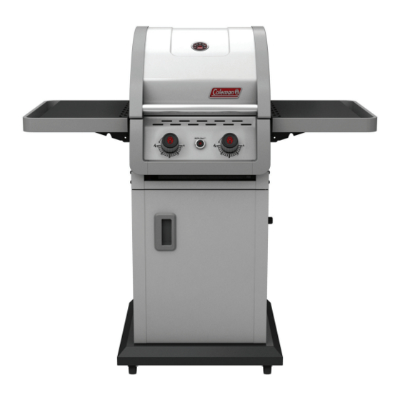
DURABILITY • POWER • PERFORMANCE
EV E N HEAT ™
B A R BE CU E
S M A L L S PA C E S
ASSEMBLY MANUAL
85-3066-4 (G35305) Propane
85-3067-2 (G35306) Natural Gas
LIMITED 5-YEAR WARRANTY
Read and save manual for future reference.
Assemble your grill immediately. Missing or damaged parts
should be claimed within 30 days of purchase.
For product inquiries, parts, warranty and troubleshooting support,
please call 1-800-275-4617.
www.colemanbbqs.com
Manual Revision #: 08272013 PD
Advertisement

Related Manuals for Coleman 85-3066-4 (G35305)


Summary of Contents for Coleman 85-3066-4 (G35305)
- Page 1 DURABILITY • POWER • PERFORMANCE EV E N HEAT ™ B A R BE CU E S M A L L S PA C E S ASSEMBLY MANUAL 85-3066-4 (G35305) Propane 85-3067-2 (G35306) Natural Gas LIMITED 5-YEAR WARRANTY Read and save manual for future reference. Assemble your grill immediately.
- Page 2 H E A V Y A R T I C L E N E E D S 2 T O L I F T THIS MANUAL MUST REMAIN WITH THE PRODUCT AT ALL TIMES To ORDER non-warranty replacement parts or accessories, or to register your warranty, please visit us on the web at www.colemanbbqs.com CAUTION...
-
Page 3: Hardware Pack
HARDWARE PACK TOOLS NEEDED FOR ASSEMBLY No. Description Part Number Qty. ¼”-20UNCX38 Screw 20120-13038-250 • #2 Phillips screwdriver (long and short) ¼”-20UNCX16 Screw 20120-13016-250 • ¼” Slotted screwdriver (long and short) φ7 Lock Washer 41400-07000-250 φ7 Washer 40300-07000-250 • Adjustable wrench 1/4”-20UNC Nut 30220-13000-250 •... - Page 4 Parts List (propane) for 85-3066-4 (G35305) Item No. Qty. Description Part No. Item No. Qty. Description Part No. Top lid assembly G353-2000-01 Support bracket A, side shelf G353-1400-01 Thermometer G522-0062-01 Support bracket B, side shelf G353-1500-01 Screw for top lid G433-0002-01 Side shelf G353-4300-01...
- Page 5 EXPLODED DIAGRAM (PROPANE) FOR 85-3066-4 (G35305) Extras Assembly Safety Tank Manual & Care Screw Hardware Manual Pack...
- Page 6 PARTS LIST (NATURAL GAS) FOR 85-3067-2 (G35306) Item No. Qty. Description Part No. Item No. Qty. Description Part No. Top lid assembly G353-2000-01 Support bracket A, side shelf G353-1400-01 Thermometer G522-0062-01 Support bracket B, side shelf G353-1500-01 Screw for top lid G433-0002-01 Side shelf G353-4300-01...
- Page 7 EXPLODED DIAGRAM (natural gas) FOR 85-3067-2 (G35306) Extras Assembly Safety Manual & Care Hardware Manual Pack...
-
Page 8: You Will Need
ASSEMBLY INSTRUCTIONS Separate the 2 different types of castors: 2 locking castors (EF) and 2 regular castors (EG). NOTE: Regular castors (EG) need to be assembled to the front of the bottom shelf (EE), and locking castors (EF) need to be assembled to the back of the bottom shelf (EE), as shown in figure A. - Page 9 ASSEMBLY INSTRUCTIONS Attach the front brace (CG) to the left and right cart side panels (EA & EB). The top of the front brace (CG) can be identified by two clips located on the top left, and right side of this part, as shown in B.
- Page 10 ASSEMBLY INSTRUCTIONS THIS STEP REQUIRES 3 PEOPLE. DO NOT ATTEMPT ALONE. EXTREMELY HEAVY! a. Position the top lid assembly and burner box assembly (A & B) onto the cart assembly (C), as shown. Front view Attach the upper back panel (CJ) to both the left and right side panels (EA &...
- Page 11 ASSEMBLY INSTRUCTIONS Assemble the left and right tracks (CL and CM) for the Quick Clean™ grease tray (CH), as shown in figure A, B and C. Back view TIP: Both the left and right tracks (CL and CM) should be inserted into the two clips located on the top of the front brace (CG), as shown in figure B.
- Page 12 ASSEMBLY INSTRUCTIONS Assemble the door support rail (CN) to the left and right upper side panels (EA and EB), as shown. WARNING: This part may have sharp edges. Wear protective gloves when assembling. YOU WILL NEED: Front view Left and Right side shelf assembly a.
- Page 13 ASSEMBLY INSTRUCTIONS c. Assemble the left and right side shelves (DC) to the side shelf support brackets (DA and DB), as shown in figure D and E. YOU WILL NEED: 6 10 Front view Close up, right side shelf...
- Page 14 ASSEMBLY INSTRUCTIONS Electronic Ignition Assembly a. Remove the ignition battery cover (CC2) and the plastic nut from the electronic ignition box (CC1). b. Position the electronic ignition box (CC1) through the opening in the right side panel (EB) and secure using the nut. Right side panel, inside view c.
- Page 15 ASSEMBLY INSTRUCTIONS a. Assemble the door assembly (EC), to the bottom shelf (EE) by inserting the fixed pin (bottom of door) into the hole provided (figure B). Front view Bottom of door b. Assemble the top of the door assembly (EC) to the door support rail (CN), by pressing in the door support pin and aligning with the hole located on the top right corner of the door.
- Page 16 ASSEMBLY INSTRUCTIONS a. Position the Quick Clean™ grease tray (CH) onto the right and left tracks (CL and CM), as shown. b. Position the Quick Clean™ grease cup (CI) in position under the under the Quick Clean™ grease tray (CH). Back view a.
- Page 17 ATTENTION: For your family’s safety, do not attempt to light this BBQ until you have reviewed pages 4-7 of the Coleman® Even Heat™ Barbecues Safety and Care Manual. All safety and leak tests MUST BE PERFORMED BY THE END USER, prior to lighting this BBQ.
-
Page 18: Additional Warnings
ADDITIONAL WARNINGS You have now completed the Assembly of your COLEMAN EVEN HEAT™ BARBECUE. ® NEXT STEPS: 1. Position your BARBECUE 2. Read SAFE USE CARE MANUAL 3. Perform Grill Safety Check-list WARNING HOT SURFACES: WARNING: FOR YOUR FAMILIES SAFETY,... - Page 19 Join the conversation facebook.com/colemangrills twitter.com/colemangrills Manufactured by Winners Products Engineering Ltd. Coleman are registered trademarks of ® The Coleman Company, Inc. used under license. ©2014 The Coleman Company, Inc. www.colemanbbqs.com...