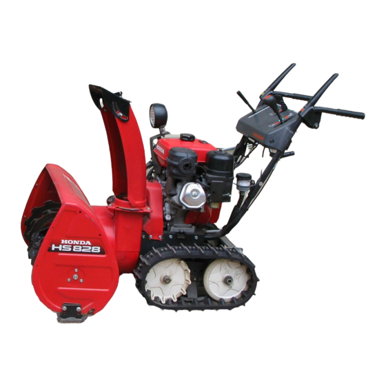
Honda HS624 Dealer Instructions
Setup and pre-delivery service
Hide thumbs
Also See for HS624:
- Owner's manual (81 pages) ,
- Owner's manual (81 pages) ,
- Owner's manual (53 pages)
Advertisement
Quick Links
Download this manual
See also:
Owner's Manual
Dealer Instructions
for
SETUP
and
PRE-DELIVERY SERVICE
HS624 • HS724 • HS828 • HS928 • HS1132
SNOWBLOWERS
1 of 17
© 2004-2011 American Honda Motor Co., Inc.—All Rights Reserved
PPD50843-F (Revised June 2011)
Advertisement

Summary of Contents for Honda HS624
- Page 1 Dealer Instructions SETUP PRE-DELIVERY SERVICE HS624 • HS724 • HS828 • HS928 • HS1132 SNOWBLOWERS 1 of 17 © 2004-2011 American Honda Motor Co., Inc.—All Rights Reserved PPD50843-F (Revised June 2011)
- Page 2 HS624 • HS724 • HS828 • HS928 • HS1132 SNOWBLOWERS IMPORTANCE OF PROPER SETUP AND PRE-DELIVERY SERVICE FOR YOUR CUSTOMER’S SAFETY Proper setup and pre-delivery service are essential WARNING to the customer’s safety and the reliability of the snowblower. Any error or oversight made during...
- Page 3 Proper setup and pre-delivery service are essential for safe, reliable operation. Your customer expects his or her Honda snowblower to be correctly assembled, adjusted, and ready for use; test the snowblower to be sure that it functions properly. Fill out the Power Equipment Pre-Delivery Check List (TO056) and give the yellow copy to the customer.
- Page 4 HS624 • HS724 • HS828 • HS928 • HS1132 SNOWBLOWERS LOOSE PARTS Remove the crate cover and open the parts carton. Remove all the parts from the carton. Check the parts against these illustrations. Description Quantity Part Number Illustration Owner’s manual...
- Page 5 HS624 • HS724 • HS828 • HS928 • HS1132 SNOWBLOWERS Description Quantity Part Number Illustration (Order the following Chute Crank Assembly parts to create a complete assembly.) Chute Drive Gear 76331-730-000 Handle Bracket Holder 76335-767-A10 Chute Handle Bush 76336-730-000 Chute Handle Bracket A...
- Page 6 HS624 • HS724 • HS828 • HS928 • HS1132 SNOWBLOWERS Description Quantity Part Number Illustration 8 x 16 mm Bolt-Washer 93404-08016-00 (all except HS1132) 6 x 9 mm Spacer 91502-ZE2-M90 (HS1132 only) TRACK-TYPE, HS724 (4) (see 8 x 41 mm Saddle-Head Bolt...
- Page 7 HS624 • HS724 • HS828 • HS928 • HS1132 SNOWBLOWERS UNCRATING 1. Remove and discard the crate top frame, side, and braces. 2. Remove and discard the shipping braces from the auger housing, track guides, engine bed side plates, track adjusting bar, and/or handlebar assembly.
- Page 8 HS624 • HS724 • HS828 • HS928 • HS1132 SNOWBLOWERS 2. Install the caps on the ends of the two handlebar CAP (2) mounting struts. 3. Attach the handlebar assembly. 8 x 41 mm SADDLE- HEAD BOLT (2) All except the HS724 track-type: a.
- Page 9 HS624 • HS724 • HS828 • HS928 • HS1132 SNOWBLOWERS 4. Wheel-driven models only: CLEVIS PIN (2) a. Apply waterproof grease to the axles. b. Slide the wheels onto the axles. c. Secure each wheel with the 8 mm clevis pin COTTER PIN (2) and cotter pin.
- Page 10 HS624 • HS724 • HS828 • HS928 • HS1132 SNOWBLOWERS 7. Install the chute crank assembly. Except HS724 Track-driven model: a. Remove the saddle-head bolt from the right handlebar and strut. 8 mm CURVED REAR CHUTE SQUARE WASHER (2) CRANK b.
- Page 11 HS624 • HS724 • HS828 • HS928 • HS1132 SNOWBLOWERS 8. Install the cable ties as shown. MEDIUM CABLE TIE HS1132 only: Clamp the SHORT CABLE TIE choke cable and throttle (factory installed) cable around the upper handlebar. LONG CABLE TIE...
- Page 12 HS624 • HS724 • HS828 • HS928 • HS1132 SNOWBLOWERS 10. All models except HS1132: a. Fasten the auger housing ends of the scraper bar using the two 8 x 16 mm bolt-washers. b. Tighten the two 8 x 16 mm bolt-washers to the specified torque.
- Page 13 HS624 • HS724 • HS828 • HS928 • HS1132 SNOWBLOWERS 2. Check the hydrostatic transmission fluid level while the RESERVOIR engine is cold. If necessary, fill the transmission reservoir to the RESERVOIR temperature compensated level shown in the following table by removing the reservoir cap and cup.
- Page 14 HS624 • HS724 • HS828 • HS928 • HS1132 SNOWBLOWERS 6. Check auger housing and scraper bar adjustment: AUGER a. Place the snowblower on a level surface. On track-type snowblowers, step on the foot pedal and set the auger in the middle position.
- Page 15 HS624 • HS724 • HS828 • HS928 • HS1132 SNOWBLOWERS 8. Check discharge deflector lever adjustment: DISCHARGE DEFLECTOR LEVER a. If the discharge deflector will not go to the HIGH position when the lever is in the HIGH position, DISCHARGE DEFLECTOR HIGH adjust the cable as needed.
- Page 16 HS624 • HS724 • HS828 • HS928 • HS1132 SNOWBLOWERS OPERATIONAL TESTS Test every snowblower to be sure it functions properly. 1. Check the electric starter operation. 2. Check the operation of the engine controls: • Turn the fuel valve ON.
- Page 17 HS624 • HS724 • HS828 • HS928 • HS1132 SNOWBLOWERS 13.Fill out the appropriate areas of the Power Equipment Pre-Delivery Check List (TO056), and give the yellow copy to the customer. PRE-DELIVERY (PDI) CHECK LIST The following pre-delivery (PDI) check list is designed for general application. There are individual exceptions to this list.


