Honda HS624 Owner's Manual
Honda snowblower
Hide thumbs
Also See for HS624:
- Owner's manual (81 pages) ,
- Dealer instructions (18 pages) ,
- Owner's manual (53 pages)
Table of Contents
Advertisement
Advertisement
Table of Contents

Related Manuals for Honda HS624


Summary of Contents for Honda HS624
- Page 2 Thank you for purchasing a Honda snowblower. We want to help you get the best results from your new snowblower and to operate it safely. This manual contains the information on how to do that; please read it carefully. This owner’s...
-
Page 3: Table Of Contents
CONTENTS ........................ SAFETY ................... Safety Label Locations Safety Information ................................COMPONENT IDENTIFICATION.. CONTROLS ......................Engine switch ....................Fuel valve......................Fuel gauge ....................... Chute crank ................................l 1 Starter grip .......... .l 1 lever(Engine speed) ............... Throttle Shift lever ...................... -
Page 4: Safety
SAFETY Safety label locations These labels warn you of potential hazards that can cause serious injury. Read them carefully. If a label comes or becomes hard to read, contact your Honda Snowblower dealer for a replacement. -
Page 5: Safety Information
(pages 17 thru start the engine. You may prevent an accident or equipment damage. Honda snowblowers are designed to give safe and dependable service if operated according to instructions. Read and understand this Owner’s Manual before operating the snowblower. - Page 6 Adjust snow discharge chute avoid hitting operator, bystanders, windows, and other objects with ejected snow. Stay clear of the snow discharge chute while the engine is running. Children and pets must be kept away from the area of operation avoid injury from flying debris and contact with the snowblower.
- Page 7 Gasoline extremely flammable explosive under certain conditions. Do not smoke or allow flames or sparks where the snowblower refueled or where gasoline is stored. Allow the engine to cool down before refueling. Refuel in a well-ventilated area with the engine stopped. Do not overfill the fuel tank, and make...
-
Page 8: Component Identification
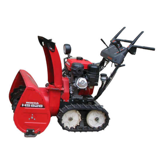
COMPONENT IDENTIFICATION (TARCK TYPE) AUGER CLUTCH LEVER CHUTE GUIDE LEVER DRIVE CLUTCH LEVER SNOW DISCHARGE CHUTE \lF-ET-f rs-- -SHIFT LEVER & THROTTLE LEVER ’ MUFFLER TRACK AC STARTER BUTTON OIL FILLER CAP TRANSMISSION FLUID RESERVOIR FUEL VALVE- CHUTE CRAN FRAME SERlAL NUMBER ENGINE SERIAL NUMBER RELEASE LEVER Record the frame and engine serial numbers... - Page 9 (WHEEL TYPE) CHUTE GUIDE LE;ER DR!VE CLUTCH LEVER SNOW DISCHARG THROTTLE LEVER AUGER CLUTCH LEVER ENGINE SWlTCH FUEL VALVE CHUTE CRAN TRANSMISSION SKID PLATE RELEASE LEVER...
-
Page 10: Controls
CONTROLS Engine switch Use the engine switch to turn the ignition system ON for starting, and to STOP the engine. ENGINE SWITCH A.C. starter button Push the starter button to operate the electric starter. STARTER BUTTON Fuel valve The fuel valve opens and closes the fuel line leading from the fuel tank to the carburetor. -
Page 11: Fuel Gauge
Fuel gauge The fuel gauge indicates the amount of fuel in the tank. When the fuel gauge needle enters the “E” range, refill the tank as soon as possible. FUEL GAUGE Chute crank Use the chute crank to turn the snow discharge chute right or left. To throw snow to the left To throw snow to the right CHUTE CRANK... -
Page 12: Starter Grip
Starter grip See page 22 for starting procedures. Pull this grip to start the engine. STARTER GRIP Throttle lever (engine speed) The throttle lever controls engine speed from SLOW to FAST, it will stay in any designated position. Set the lever to CHOKE when the engine is cold. SLOW THROTTLE LEVER... -
Page 13: Shift Lever
Shift lever shift lever selects FORWARD (F), NEUTRAL (N), or REVERSE hydrostatic transmission drive. The shift lever also controls the transmission drive ratio; moving the lever farther from NEUTRAL increases drive speed. While clearing snow, use the shift lever to control drive speed, so you can leave the throttle lever in the FAST position for best snow-clearing performance. -
Page 14: Drive Clutch Lever And Auger Clutch Lever
Drive clutch lever and Auger clutch lever Use these controls to engage the snow blowing mechanism and/or drive mechanism. DRNE CLUTCH LEVER AUGER CLUTCH LEVE Squeeze to engage the Squeeze to engage the drive transmission. snow blowing mechani NOTE: When both levers are squeezed, the drive clutch... -
Page 15: Skid Plate, Scraper
Skid plate, scraper Adjust the skid plates for the auger ground clearance best suited to your snow removal conditions. To prevent accidental starting, turn the engine switch to the OFF position and disconnect the spark plug cap. 1 .Place the snow thrower on a level surface and set the height adjustment pedal in the middle position., 2.Move... -
Page 16: Foot Pedal
Foot pedal (Track type only) Use the pedal for adjusting the height and angle of the machine in relation to the tracks. 1. Hold the handles and step on the pedal. 2. Raise or lower the machine to the desired position and release the pedal. : Hard snow or fine finish MIDDLE : Normal use... -
Page 17: Transmission Release Lever
Transmission release lever transmission release lever positions, RELEASED ENGAGED. Set the lever in the ENGAGED position when throwing snow; set it in the RELEASED when pushing the snowblower. Never shift the transmission release lever on slopes. The snow throwing mechanism may operate suddenly, causing serious injury or accident. -
Page 18: Pre-Operation Check
Check the fuel gauge, and refill the tank if the fuel level is low. Allow the engine to cool down before refueling. Refuel carefully to avoid overfilling spilling fuel. There should be no fuel in the filler neck. FUEL TANK CAPACITY: HS624: 3.5 0 (0.92 US gal, 0.77 Imp gal) HS828: 6.0 0 (1.59... - Page 19 This is no cause for concern. lf spark knock or pinging occurs at a steady engine speed, under normal load, change brands of gasoline. If spark knock or pinging persists, see an authorized Honda snowblower dealer. pEiq Running the engine with persistent spark...
-
Page 20: Engine Oil
If the level is low, fill to the top of the oil filler neck with the recommended oil. 50-F UPPER LEVEL OIL FILLER CAP AND.DIPSTICK OIL CAPACITY: HS624 0.60 4 (0.63 US qt ,0.53 Imp qt) HS828 1.10 Q(1.16... -
Page 21: Hydrostatic Transmission Fluid
UPPER LEVEL TRANSMISSION LOWER LEVEL FLUID RESERVOIR If the fluid level is low, add HONDA HYDROSTATIC FLUID. The use of other hydrostatic fluids will reduce transmission performance ZW&EI~ damage the transmission. -
Page 22: Auger And Blower Bolts
Auger and blower bolts Check the auger and blower for loose or broken bolts. If broken, replace them with new ones (page 41 1. BLOWER SHEAR @OLT AUGER SHEAR BOLT Other checks 1. Check all bolts, nuts and other fasteners for security. -
Page 23: Starting The Engine
STARTING THE ENGINE Never run the engine in an enclosed or confined area. Exhaust contains exposure cause loss poisonous carbon monoxide gas; consciousness and may lead to death. 1. Move the shift lever to “N” (Neutral). “N” (Neutral) 2. Turn the fuel valve to the ON position. Be sure that the drain knob is tightened securely. - Page 24 3. Set the transmission release lever in the ENGAGED position. ENGAGED TRANSMISSION RELEASE LEVER 4.ln cold weather and when the engine is cold, move the throttle lever to CHOKE position. THROTTLE LEVER...
- Page 25 [ELECTRIC START MODELS1 5. Connect your power cord to the switch box and the male end of the power cord to a properly grounded 120 Volt A/C outlet. POWER CORD To minimize the possibility of potentially dangerous electrical shocks, always use a 3-conductor power cord with...
- Page 26 7. Push the starter button until the engine starts. After the engine starts, disconnect the power cord from the electrical outlet first, and then from the switch box. PUSH ine fails Do not operate the starter for more than 1 minute. It the engl Inul start,...
- Page 27 9. After starting the engine, allow it to run for a few seconds to warm it up to operating temperature. As the engine stabilizes, gradually move the throttle lever to the SLOW position. THROTTLE LEVER lO.While warming the engine up, also warm the transmission as follows: (1) Check that the shift lever is in the “N”...
-
Page 28: Snow Blower Operation
SNOWBLOWER OPERATION Before operating this equipment you should read and understand SAFETY INFORMATION on page 3,4,5 and 6. 1. Start the engine according to the procedures described in page 22 . 2. Move the throttle lever to the FAST position for normal operation. 3.Release the auger clutch lever, and move the shift lever to select the... - Page 29 6. Squeeze the auger clutch lever. The machine will clear snow when you squeeze the auger clutch lever. AUGER CLUTCH LEVER 7. Squeeze the drive clutch lever. If the transmission release lever (p. 23) is in the ENGAGED position, the shift lever (p. 27) is in the FORWARD (F) position, the hydrostatic drive will propel the snowblower...
- Page 30 To move from one place to another, or to change direction, use the drive clutch lever only. Release both the drive clutch lever and auger clutch lever then squeeze the drive clutch lever. DRIVE CLUTCH LEVER 8. Release the clutch levers to stop clearing and moving. LEVER DRIVE CLUTCH AUGER CLUTCH LEVER...
-
Page 31: Clearing Snow
Clearing snow For best efficiency, clear snow before it melts, refreezes and hardens. Do not reduce engine speed while clearing snow. Operating tips for clearing hard or deep snow: Reduce forward speed. If that is not sufficient, use the shift lever to clear snow with a back and forth motion. - Page 32 If you always operate the engine at altitudes higher than 1,600 meters (6,000 feet) above sea level, have an authorized Honda Snowblower dealer perform this carburetor modifications.
-
Page 33: Stopping The Engine
STOPPUNG THE ENGINE EMERGENCY STOP STOP engine in an emergency, turn engine switch immediately. ENGINE SWlTCH iack to the “N” (Neutral) To restart the engine, move the shift lever position. NORMAL STOP 1. Release the auger and drive clutch levers. The drive and snow throwing mechanism will stop operation. - Page 34 3.Turn the throttle lever to the SLOW position. THROTTLE LEVER SLOW 4. Turn the engine switch to the OFF position. ENGINE SWITCH 5. Turn the fuel valve to the OFF position. Do not park the snowblower on a slope as it is not equipped with parking brake mechanism.
-
Page 35: Maintenance
To avoid overturning, place the snowblower on a level surface before performing inspection and maintenance. Use only genuine HONDA parts or their equivalent. Replacement parts which are not of equivalent quality may damage the snowblower. -
Page 36: Maintenance Schedule
UThese items should be serviced by an authorized Honda dealer, unless the owner has the proper tools and is mechanically proficient. See the Honda Shop Manual for service information. -
Page 37: Tool Kit
Tool kit BLOWER SHEAR BOLT SPARK PLUG WRENCH 6mm SELF LOCK NUT WRENCH HANDLE AUGER SHEAR BOLT (31 10 x 14mm WRENCH 6mm HEX NUT (3) 12 x 14mm WRENCH TOOL BAG... -
Page 38: Engine Oil Change
2. Remove the drain plug and filler cap, and drain the oil. Retighten the plug securely. 3. Fill the crankcase with the recommended oil (see page 19) and check the level. OIL CAPACITY: HS624 0.60 Q (0.63 US qt ,0.53 Imp qt) HS828 1 .lO Q (1.16 US qt ,0.97... -
Page 39: Spark Plug Service
Spark plug service Recommended spark plug: BPR5ES (NGK) , W 1 GEPR-U (NIPPONDENSO) lf the engine has been running, the muffler will be very hot. Be careful not to touch the muffler while it is hot. To ensure proper engine operation, spark plug must... -
Page 40: Track-Adjustment
Track-adjustment Make sure the tracks are clean and dry before adjustment. The tracks cannot be correctly adjusted if clogged with snow or debris, or coated with ice. Check track deflection by pressing down midway between the wheels with a force of 15 kg (33 lb). When correctly adjusted, it should be: 27.0-33.0... -
Page 41: Wheel/Tire Inspection
Wheel/Tire Inspection Check side wall and tread surface of each tire for cracks, damage, or excessive wear. Check the tire pressure Tire pressure: 80- 100 kPa (0.8- f .O kg/cm* , 11.4- 14 psi) -
Page 42: Auger/Blower Inspection
If any of the shear bolts are broken, replace them with the one furnished with the snowblower. Additional shear bolts and nuts are available from authorized Honda snowblower dealers. Shear bolts are designed to break under... -
Page 43: Transporting
Weight of snowblower : (Operating weight) HS828 HS624 84 kg (185 Ibs) kg (256 Ibs) 88 kg (194 Ibs) 105 kg (231 Ibs) 3. The loading ramp must be long enough so that its slope is 15O or less: 4. - Page 44 3. Run the snowblower slowly up the loading ramp. Be careful to avoid striking the chute or other parts of the machine. 1.5 mm (4.9 ft) FORWARD minimum headroom 4.After the snowblower is in the truck, stop the engine, and turn the fuel valve to the OFF position.
-
Page 45: Storage
Use gasoline conditioners that are formulated to extend storage life. Contact your authorized Honda water pump dealer for recommen- dations of gasoline conditioners. Before storing the snowblower for an extended period: 1. Be sure the storage area is free of excessive humidity and dust. - Page 46 DRAIN KNOB 3. Clean the sediment cup. a. Turn the fuel valve OFF, remove empty and clean the fuel strainer cup. b. Reinstall the cup and packing and tighten securely. O-RING SEDIMENT CUP 4.Remove the spark plug and pour a tablespoonsful of clean motor oil into the cylinder.
- Page 47 5. Pull the starter grip until resistance is felt. This closes the valves protects the engine from internal corrosion. STARTER GRIP 6. Apply oil to the following parts for lubrication and rust prevention.
-
Page 48: Troubleshooting
If sparks occur, try to start the engine according to the instructions. 7. If the engine still does not start, take the snowblower to an authorized Honda dealer. If the auger or blower does not operate, check the shear bolts (p. 41... -
Page 49: Specifications
Clearing capacity 37 Ton/hour 35 Ton/hour Continuous operating time 3.5 hours Engine Model HONDA GX 160 K 1 Maximum output 6 HP/4,000 Displacement cm3 (9.9 cu-in) Bore x stroke 68 x 45 mm (2.7 x 1.8 in) - Page 50 Snow throwing distance (differs according to the kind of snow) 37 Ton/hour Clearing capacity 35 Ton/hour 2.5 hours Continuous operating time Engine HONDA GX240 Model 8 HP/3,600 Maximum output 242 cm3 (14.8 cu-in) Displacement 73 x 58 mm (2.9 x 2.3 in)
- Page 51 Honda Power Equipment Customer Service Office. You can write to: American Honda Motor Co., Inc. Honda Power Equipment Division Customer Service Office 4475 River Green Parkway Duluth, Georgia 30136-9420 (4041497-6400 Or telephone: When you write or call, please give us this information:...
- Page 52 When you write or call, please provide the following information: • Model and serial numbers • Name of the dealer who sold the Honda power equipment to you • Name and address of the dealer who services your equipment •...
-
Page 53: Index
INDEX ................. COMPONENT IDENTIFICATION ......................CONTROLS Chute crank ....................Chute guide ....................Drive clutch lever and clutch lever .............. Engine switch ....................Foot pedal ....................... Fuel valve......................Fuel gauge....................... Shift lever ....................... Skid plate, Scraper ..................Starter grip ..................... speed) ................