Table of Contents
Advertisement
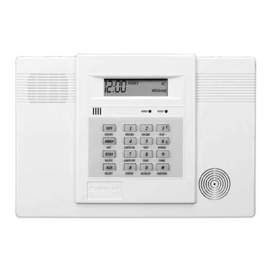
ADEMCO LYNXR Series
Security Systems
LYNXR/LYNXR24 and LYNXR-EN
Installation and Setup Guide
ARMED
READY
1
2
3
OFF
ESCAPE
RECORD
VOLUME
PLAY
4
AWAY
5
6
ADD
LIGHTS ON
TEST
BYPASS
7
8
9
STAY
DELETE
LIGHTS OFF
CODE
CHIME
0
#
AUX
SELECT
STATUS
NO DELAY
FUNCTION
K5963V3 5/04 Rev. A
WWW.DIYALARMFORUM.COM
WWW.DIYALARMFORUM.COM
Advertisement
Table of Contents

Related Manuals for Honeywell LYNXR


Summary of Contents for Honeywell LYNXR
- Page 1 ADEMCO LYNXR Series Security Systems LYNXR/LYNXR24 and LYNXR-EN Installation and Setup Guide ARMED READY ESCAPE RECORD VOLUME PLAY AWAY LIGHTS ON TEST BYPASS STAY DELETE LIGHTS OFF CODE CHIME SELECT STATUS NO DELAY FUNCTION K5963V3 5/04 Rev. A WWW.DIYALARMFORUM.COM WWW.DIYALARMFORUM.COM...
-
Page 2: Recommendations For Proper Protection
RECOMMENDATIONS FOR PROPER PROTECTION The Following Recommendations for the Location of Fire and Burglary Detection Devices Help Provide Proper Coverage for the Protected Premises. Recommendations for Smoke and Heat Detectors With regard to the number and placement of smoke/heat detectors, we subscribe to the recommendations contained in the National Fire Protection Association's (NFPA) Standard #72 noted below. -
Page 3: Table Of Contents
TESTING THE SYSTEM............................51 SYSTEM COMMUNICATION ..........................52 TROUBLESHOOTING GUIDE ..........................54 CONTACTING TECHNICAL SUPPORT......................56 REGULATORY AGENCY STATEMENTS ......................57 SPECIFICATIONS..............................58 LYNXR/LYNXR24 PROGRAMMING DEFAULT TABLES.................59 LYNXR-EN PROGRAMMING DEFAULT TABLES ....................60 INDEX..................................63 LIMITATIONS OF THIS SYSTEM STATEMENT....................69 WARRANTY ................................70 SUMMARY OF CONNECTIONS DIAGRAM .......................71 –3– WWW.DIYALARMFORUM.COM... -
Page 4: System Features
System Features LYNXR and LYNXR-EN are not intended for UL985 Household Fire applications unless a 24-hour backup battery (P/N LYNXRCHKIT-HC) is installed. U U U U L L L L Powerline Carrier Devices are not UL Listed for fire or burglary functions and are intended for home automation. -
Page 5: Mounting The Control
01009-003-V0 Desktop Mounting If desired, an optional mounting base (model LYNX-DM, purchased separately) allows the LYNXR-Series controls to be used on a desktop. 1. Slide the control panel onto the mounting base locking tabs 2. -
Page 6: Wiring Connections
The LYNXR-EN supports the two-way voice feature/Alarm Audio Verification. Devices for turning on/off lights and appliances. Requires the use of an The LYNXR and LYNXR24 require the ADEMCO 1332X10 transformer. installation of the LYNXAVM. PHONE LINES Use either the plug-in jacks or the screw terminals. - Page 7 Connect the com/data/sync/ lines from the ADEMCO 1332X10 transformer to terminals 9, 13, and 14, respectively. Note: If not using the supplied Ademco connection cable, you may need to reverse the black and yellow wire connections. Refer to the ✻80 Device Programming Menu Mode section for details on programming Powerline Carrier Devices.
- Page 8 WARNING: TO PREVENT RISK OF SHOCK DISCONNECT TELEPHONE LINE AAV / LRR AT TELECOM JACK BEFORE TRIGGER SERVICING THIS UNIT. (LYNXR/LYNR24) EARTH TRIGGER GROUND PHONE ZONE (LYNXR-EN) SOUNDERS PLCD RJ11 JACK DATA RING RING SYNC HARD WIRED INCOMING ZONE HANDSET...
-
Page 9: Ac Power And Backup Battery
ADEMCO 1332/1332X10 (1332CN in Canada). Refer to the wiring table below for wire gauge and length. Distance from Transformer Wire Gauge Use only the provided ADEMCO 1332/1332X10 or 1332CN Transformer to Control Up to 75 feet 75 to 150 feet 150 to 300 feet Wiring to the AC Transformer must not exceed 300 feet using 16-gauge wire. - Page 10 AC Power and Backup Battery AC Power and Rechargeable Backup Battery The LYNXR Series is equipped with an integral, replaceable, rechargeable battery pack composed of six (6) rechargeable 1.2-volt nickel-metal hydride batteries. Select the appropriate battery pack, based on the installation’s requirement, and install the battery pack.
-
Page 11: Installing Wireless Zones
Installing Wireless Zones General Information Zones: The control supports up to 24 wireless zones using 5800 Series transmitters, and up to 16 wireless buttons. Range: The built-in RF receiver can detect signals from wireless transmitters within a nominal range of 200 feet. Transmitters: 5800 Series transmitters have built-in serial numbers that must be entered into the system using the ✻56 or ✻83 interactive mode, or input to the control via the downloader. - Page 12 Installing Wireless Zones Transmitter Battery Life • Batteries in the wireless transmitters may last from 4–7 years, depending on the environment, usage, and the specific wireless device being used. Factors such as humidity, high or low temperatures, as well as large swings in temperature may all reduce the actual battery life in a given installation.
- Page 13 Installing Wireless Zones 5800 Series Transmitter Loop Numbers (Refer to this information when programming transmitters) The following illustration shows the compatible transmitters, their associated input types and loop designations. Notes: (1) Loop 4 must be enrolled on the 5801, 5804, 5804BD, 5804BDV, 5804E and 5804WATCH transmitters, whether or not the loop is used.
-
Page 14: Mechanics Of Programming
FUNCTION + VOLUME+ [3] or [6]. Upon exiting the Program Mode, the system will reset the volume to the default value (mid level). Certain features differ between the LYNXR/LYNXR24 and the LYNXR-EN models. Verify the specific model being installed prior to the system programming. -
Page 15: Zone Response Type Definitions
Zone Response Type Definitions General Information During programming, you must assign a zone type to each zone, which defines the way in which the system responds to faults in that zone. Zone types are defined below. Type 00 Zone type 00 is used to program a zone that is not used. Zone Not Used Zone type 01 is usually assigned to sensors or contacts on primary entry and exit Type 01... - Page 16 Zone Response Type Definitions Type 07 Zone type 07 is usually assigned to a zone containing an Emergency 24-hour button (audible emergency). Audible Zone Characteristics: Alarm • Sends a report to the central station, and provides alarm sounds externally and at the keypad. Zone type 08 is usually assigned to a zone containing a button for use Type 08 in personal emergencies or to a zone containing monitoring devices...
-
Page 17: Data Field Descriptions
LYNXR/LYNXR24 - Applies to Long Range Radio Output if “0” sounds. is selected in field ✻91 LYNXR-EN - Applies to Long Range Radio Output if Long Range Radio is connected to the Trigger Single (Neg.) terminal #8. This Control complies with NFPA requirements for temporal pulse ✻... - Page 18 Data Field Descriptions The system will wait the time entered before sounding alarm upon entering Entry Delay 01 ✻ if system is not disarmed. UL installations: must be set for a maximum of 00-99 = entry delay time in seconds. 45 seconds The system will wait the time entered before sounding alarm upon ✻...
- Page 19 ✻ the field press The telephone message can be terminated (acknowledged) by pressing any key on the telephone keypad. Pressing any key on the local LYNXR keypad will terminate (acknowledge) both the follow me and the local reminder announcements. Note: The follow me reminder announcement will be terminated if any other event requires the system to dial out or if and audible alarm has occurred.
- Page 20 With ADEMCO Contact ID® Reporting: Enter a digit in the first box to enable the zone to report. Use a different digit for each zone until you have used up available digits. If the number of zones exceeds the number of available digits, begin with digit 1 again.
-
Page 21: Exit Error Report Code
Data Field Descriptions ✻ ✻ SYSTEM STATUS REPORT CODES ( 59– If the system is armed and an entry/exit or interior zone is still open ✻ Exit Error Report Code after the exit delay time has expired, an alarm will sound at the (See notes above) keypad and external sounder. -
Page 22: Test Restore Report Code
Data Field Descriptions ✻ ✻ RESTORE REPORT CODES ( 70– 76) Continued Sent when a transmitter that previously sent in a “low battery” message ✻ RF Transmitter Low Batt. Restore Code has sent a message indicating it no longer has a low battery condition. (See notes above) Sent when the test mode is exited. -
Page 23: Number Of Reports In Armed Period
Data Field Descriptions The features programmed in Field ✻ 91 differ between LYNXR models. Ensure you use the correct option for the model you are installing! For LYNXR/LYNXR24, this option is used to enable the Long Range ✻ LYNXR/LYNXR24 Radio, Alarm Audio Verification and/or Remote Phone Control options. - Page 24 Data Field Descriptions Other Programming Commands ✻ 56 ENHANCED ZONE PROGRAMMING MODE ✻ Interactive menu mode used for programming zone attributes and report codes. Refer to the Enhanced Zone Programming Mode section for procedure. ✻ 80 DEVICE PROGRAMMING MENU MODE ✻...
-
Page 25: Enhanced Zone Programming Mode
✻ 56 Enhanced Zone Programming Mode This is an interactive menu mode that is used to program zone numbers, zone types, alarm and report codes, and to identify the type of loop input device. This mode can also be used for entering 5800 Series transmitter serial numbers. -
Page 26: Zone Number
✻ 56 Enhanced Zone Programming Mode While in Program mode, press ✻ 56 to enter Zone Programming Menu Mode. ✻ Refer to the zone assignment table for 56 on the separate programming form. The following explains the ✻ 56 prompts in detail. The left two columns identify the prompts and list the available entries for each. - Page 27 ✻ 56 Enhanced Zone Programming Mode RF Learning - Two (2) transmissions (2 key depressions) at least 5 seconds apart will be required for BR type devices (device type 5). Two beeps will sound after the second transmission, confirming that the loop number and serial number have been learned.
-
Page 28: Serial Number
✻ 56 Enhanced Zone Programming Mode Manual entry Enter "1" to advance to Serial number prompt (1b). Copy the previous serial number Enter “2” to copy the previous serial number entered. Return to Prompt (E) Enter “#” to return to Loop Number prompt (E). Enter transmitter later ✻... -
Page 29: Device Programming Menu Mode
✻ 80 Device Programming Menu Mode Powerline Carrier devices (eg., X-10 brand devices) are programmable switches that can be used to perform many different functions. They can be used to turn lights on and off, control sounders, or for status indications. - Page 30 ✻ 80 Device Programming Menu Mode The "STOP" programming determines when and under what conditions the device will be de- STOP activated. The following options are available: Upon Restore of a Zone List Restore Zone List: If a "ZONE LIST" is used as the “Stop” event, the device will de-activate when all the zones in that list restore from a previous fault, trouble, or alarm condition.
-
Page 31: Powerline Carrier Device
✻ 80 Device Programming Menu Mode The following explains these prompts in detail. The left two columns identify the prompts and list the available entries. The right-most column provides a further explanation of the entries. Note: Entering a number other than one specified will give unpredictable results. Entering “1”... -
Page 32: Zone List Menu Mode
✻ 81 Zone List Menu Mode While in Program mode, press ✻ 81 to enter Zone List Menu Mode. This mode is used to program zone ✻ lists for output devices (programmed in 80 menu mode) or Chime-by-Zone in Zone List 3. NOTES: •... -
Page 33: Enhanced Sequential Mode
✻ 83 Enhanced Sequential Mode By using this mode, you can add, delete, or change the serial number of a transmitter in a zone, but retain ✻ all other existing data that has been programmed for that zone. Note that the 83 Enhanced Sequential mode requires that all zone information must first be entered using the ✻... - Page 34 ✻ 83 Enhanced Sequential Mode Note: If “L” is displayed, the serial number for this transmitter has Enroll mode 0 = advance to next zone to be enrolled already been entered, however, it may still be confirmed, viewed or deleted. 1 = enter now and proceed to SERIAL NUMBER prompt (1b).
- Page 35 ✻ 83 Enhanced Sequential Mode This prompt can be used to enroll the transmitter serial number via Serial number RF transmission or manually. If using the RF Learning Mode there Enter transmitter’s 7- digit serial number via RF is no need to manually enter a serial number. Proceed directly to RF learning or manually.
-
Page 36: Assign Zone Voice Descriptors
✻ 84 Assign Zone Voice Descriptors Use this mode to assign voice descriptors for each zone. These are the descriptors that are announced when the system announces any event involving a zone number. Each descriptor can consist of up to 3 words. Press ✻... -
Page 37: Voice Vocabulary Index
✻ 84 Assign Zone Voice Descriptor VOICE VOCABULARY INDEX ½ second pause SYSTEM WORDS GARAGE 61 PATIO ZERO AC LOSS 49 GUEST ROOM 62 POLICE ZONES ARMED ALARM 18 POOL AWAY ATTIC BYPASSED CHIME 63 REAR DISARMED HALL 19 ROOM BABY DISARM SYSTEM Custom Word #1... -
Page 38: Record Custom Voice Descriptors
✻ 85 Record Custom Voice Descriptors Use this mode to record up to 5 custom voice descriptors. Press ✻ 85 while in Programming mode. Note: Entering a number other than one specified will give unpredictable results. Entering “1” advances to the next prompt below. Assign custom voice descriptors Entering “0”... -
Page 39: Voice Prompt Programming
Used to repeat a voice prompt. (This function cannot be used while entering phone or account numbers.) Notes: (1) Keying in any new command will terminate the active voice prompt. (2) If an irrelevant command is entered LYNXR will generate a long rejection beep and repeat the previous voice prompt. “ADD/ AWAY ”... - Page 40 Program each option as shown below. Use the 6 ↓ and 3 ↑ keys to scroll through the voice menu and follow the voice prompts to program the LYNXR. The LYNXR will enroll a sensor once the transmitter has been activated two times. The system will confirm the enrollment following each subsequent activation of the same transmitter.
- Page 41 "Keys" transmitter twice the key number Press Press [SELECT] [ADD] LYNXR automatically saves phone and account number data once all available digits are entered. To Add First Central Station Phone Number Select Enter first Enter first central station central station "First Central...
- Page 42 (up to 4 or 10 digits) Number" Press Press [SELECT] [ADD] Refer to the LYNXR Series Installation and Setup Guide to view the complete set of Template (default table) selections. To Program a Template (Default Table) Select Select template "Templates"...
-
Page 43: Remote Programming Information
DIP switch] internal style), a HAYES brand Optima 336 external, a HAYES brand Optima 24 Plus FAX96, or an Ademco CIA Modem. • Compass Downloader for Windows (at revision level supporting LYNXR, LYNXR24 or LYNXR-EN). ✻ Initial Download: Enter Installer Code + # + 5. This sets field 95 to 4 rings, and system to “no call-back”... - Page 44 Remote Programming/Control (Downloading) • Command the system to upload a copy of its resident program to the office. • Set the time • View/Modify • X-10/ Scheduling • Read: arming status, AC power status, lists of faulted zones, bypassed zones, zones currently in alarm, zones currently in trouble, and RF sensors with low battery conditions;...
-
Page 45: System Operation
System Operation Security Codes Installer Code The installer programs the 4-digit Installer Code initially as part of the programming procedure. The factory default Installer Code is 4-1-1-2, but may be changed in field ✻ The Installer Code is the only code that can enter Programming mode and also, in normal operation mode, is used to enter the Master Code, which allows access to the normal functions of the system. -
Page 46: Keypad Functions
System Operation Keypad Functions The keypad allows the user to arm and disarm the system, and perform other system functions, such as bypassing zones. Zone and system conditions (alarm, trouble, bypass) are displayed in the display window. When an alarm occurs, keypad sounding and external sounding will occur, and the zone(s) in alarm will be displayed on the keypad. -
Page 47: Remote Phone Control Feature
System Operation Speaker Phone Operation (LYNXR-EN Only) NOTE The ARMED and READY LEDs blink alternately [#] + To place a call or answer a call using the speaker phone: when the Speaker Phone is active. To flash (switch between two calls using call waiting):... -
Page 48: Alarm Audio Verification (Two-Way Voice Feature)
Talk Mode: Pressing the [1] key on the touch tone phone, enables one-way voice communication from the central station to the violated premises, and allows the operator to talk communicate through the LYNXR-EN speaker. In this mode the ARMED (red) and READY (green) LEDs blink alternately. -
Page 49: Follow Me" Reminder Feature
LYNXR keypad will continue. If the message has timed out the system will redial the programmed number a maximum of seven additional times or until it is acknowledged. Pressing any key on the LYNXR keypad will terminate (acknowledge) both the follow me reminder and the local reminder announcements. -
Page 50: Trouble Conditions
System Operation Trouble Conditions The word “FAULT” on the keypad’s display, accompanied by a rapid “beeping” at the keypad, indicates that there is a trouble condition in the system. Pressing any key can silence the audible warning sound. Instruct users to call for service immediately upon seeing any of the following messages. “Fault”... -
Page 51: Testing The System
Testing the System Test Mode After installation is completed, the security system should be carefully tested, as follows. 1. With the system in the disarmed state, check that all zones are intact. If the READY LED is not lit, press the [ ✻... -
Page 52: System Communication
This is the “expanded” digit. 4+2 Format Comprises a 4-digit subscriber number and 2-digit report code. ADEMCO Contact ID® Comprises a 4-digit subscriber number, 1-digit event qualifier Reporting Format (“new” or “restore”), 3-digit event code, and 3-digit zone number, user number, or system status number (see the following page). -
Page 53: Contact Id Event Codes
SSSS R B b R B R B R B (R B )b ADEMCO Contact ID® Reporting takes the following format: CCCC Q EEE GG ZZZ where: CCCC = Customer (subscriber) ID = Event qualifier, where: E = new event, and R = restore... -
Page 54: Troubleshooting Guide
Troubleshooting Guide S Y S T E M ( i n c l u d i n g W i r e l e s s ) SYMPTOM POSSIBLE CAUSE REMEDY 1a. Transmitter not properly powered. Check or change transmitter's battery. Transmitter signal not received at 1b. - Page 55 Troubleshooting Guide C O N T R O L SYMPTOM POSSIBLE CAUSE REMEDY The word “AC” is not 1a. Interrupted AC power supply. 1a. Check transformer connection and displayed. powerline circuit breaker. Digital communicator 2a. System in Test mode. 2a. Remove from Test mode. message not being 2b.
-
Page 56: Contacting Technical Support
• Note your ADEMCO customer number and/or company name. Having this information handy will make it easier for us to serve you quickly and effectively. You may contact Technical Support via Toll Free Fax. Please include your return fax number. You will receive a reply within 24 hours. -
Page 57: Regulatory Agency Statements
Regulatory Agency Statements UL NOTICE: This is a "Grade A" residential system. FCC ID: CFS8DLLYNXREN-2 CANADA: 573F-LYNXREN2 FCC STATEMENT THIS DEVICE COMPLIES WITH PART 15 OF FCC RULES. OPERATION IS SUBJECT TO THE FOLLOWING TWO CONDITIONS: (1) THIS DEVICE MAY NOT CAUSE HARMFUL INTERFERENCE, AND (2) THIS DEVICE MUST ACCEPT ANY INTERFERENCE RECEIVED, INCLUDING INTERFERENCE THAT MAY CAUSE UNDESIRED OPERATION. -
Page 58: Specifications
(e.g., ADEMCO’s WAVE2EX). LONG RANGE RADIO: Rated 12mA@12-volt nominal (negative trigger signal). 3. Communication: FORMATS SUPPORTED: ADEMCO Express, 10 characters/sec, DTMF (TouchTone) Data Tones, 1400/2300Hz ACK, 1400Hz KISSOFF. ADEMCO Contact ID® Reporting, 10 characters/sec., DTMF (TouchTone) Data Tones, 1400/2300Hz ACK, 1400Hz KISSOFF. -
Page 59: Lynxr/Lynxr24 Programming Default Tables
LYNXR/LYNXR24 PROGRAMMING DEFAULT TABLES (boldface indicates defaults that differ between tables) Function Table 1 Table 2 Table 3 Table 4 Installer code 4112 4112 4112 4112 Quick arm enable Keypad backlight timeout Forced bypass RF house ID code Powerline carrier device house code... -
Page 60: Lynxr-En Programming Default Tables
LYNXR-EN PROGRAMMING DEFAULT TABLES (boldface indicates defaults that differ between tables) Function Table 1 Table 2 Table 3 Table 4 *20 Installer code 4112 4112 4112 4112 *21 Quick arm enable *22 Keypad backlight timeout *23 Forced bypass *24 RF house ID code... - Page 61 56 ZONE ASSIGNMENT/ALARM REPORT CODES FOR TABLE 1 ✻ Zone No. Zone Type Alarm Code Input Type Loop Number Zone Descriptor 3 (RF) 47, 04 (FRONT DOOR) 3 (RF) 33, 04 (BACK DOOR) 3 (RF) 80 (WINDOW) 3 (RF) 56 (MOTION DETECTOR) 5 (BR) 5 (BR) 5 (BR)
- Page 62 80 DEFAULT TABLE: APPLIES TO DEFAULT TABLE 4 (devices 2-7 have no default values) ✻ Start Stop Zone Type Restore of Zone type Device Number Action Event Zone List System Operation Zone List System operation ** NOTE: If using an X-10 Powerhouse Security SH10A siren as device 8, you must change the device action default to “3” if using default table 4.
-
Page 63: Index
Custom Descriptor Number .............38 AC Transformer ................. 6 Custom Voice Descriptors ..........24, 38 ADEMCO 1332/1332X10 ............9 ADEMCO Express ............. 19, 58 ADEMCO Low Speed............19, 58 Data Encryption ...............43 Alarm Audio Verification (AAV)/Remote Phone Control ..23 Data Field.................14 Alarm Audio Verification (Two-Way Voice Feature).... - Page 64 Event Logging...............22, 59, 60 Low Speed ................52 Exit Alarm ................21 LYNX-DM...................5 Exit Delay ...............17, 18, 59, 60 LYNXR/LYNXR24 Programming Default Tables ....59 Exit Delay Restart ............. 18, 46 LYNXRCHKIT-HC..............10 Exit Door.................. 17 LYNXRCHKIT-SC ..............10 Exit Error Alarm Displays ............49 LYNXR-EN Programming Default Tables ......60...
- Page 65 Radionics.................. 19 Technical Support..............56 Radionics/SESCOA ..............58 Telco Handoff................43 Range ..................11 Temporal Pulse................ 17 Real-Time Clock Display ..........17, 59, 60 Test Mode ...............46, 51, 54, 55 Rechargeable Backup Battery ........... 9 Test Report Code ............21, 59, 60 Record a Message..............
- Page 66 -Notes- – 66 – WWW.DIYALARMFORUM.COM WWW.DIYALARMFORUM.COM...
- Page 67 -Notes- – 67 – WWW.DIYALARMFORUM.COM WWW.DIYALARMFORUM.COM...
- Page 68 -Notes- – 68 – WWW.DIYALARMFORUM.COM WWW.DIYALARMFORUM.COM...
-
Page 69: Limitations Of This System Statement
WARNING THE LIMITATIONS OF THIS ALARM SYSTEM While this System is an advanced design security system, it does not offer guaranteed protection against burglary, fire or other emergency. Any alarm system, whether commercial or residential, is subject to compromise or failure to warn for a variety of reasons. -
Page 70: Warranty
24 months from the date stamp control on the product or, for products not having an Ademco date stamp, for 12 months from date of original purchase unless the installation instructions or catalog sets forth a shorter period, in which case the shorter period shall apply. -
Page 71: Summary Of Connections Diagram
Notes: Connection of the fire alarm signal to a fire alarm headquarters or a central station shall be permitted with the approval of the local authority having jurisdiction. The burglar alarm signal shall not be connected to a police emergency number. The System must be checked by a qualified technician once every three years. - Page 72 165 Eileen Way, Syosset, New York 11791 Copyright © 2004 Honeywell International Inc. ‡K5963V3oŠ www.honeywell.com/security K5963V3 5/04 Rev. A WWW.DIYALARMFORUM.COM WWW.DIYALARMFORUM.COM...