
Related Manuals for Mackie SR40-8


Summary of Contents for Mackie SR40-8
- Page 1 Go To Bulletins SR40•8 SR56•8 SERVICE MANUAL ©1997, ©1999 MACKIE DESIGNS, INC. VERSION 1.1 820-176-00 Page 3 is interactive...
- Page 2 C AU TIO N A V IS R IS K O F E L E C T R IC S H O C K D O N O T O P E N R IS Q U E D E C H O C E L E C T R IQ U E N E P A S O U V R IR C A U T IO N : T O R E D U C E T H E R IS K O F A T T E N T IO N : P O U R E V I T E R L E S...
-
Page 3: Table Of Contents
Click on any item to open that page CONTENTS INTRODUCTION..............4 TECHNICAL SUPPORT ................4 DISCLAIMER ....................4 SYSTEM OVERVIEW ............5 THE SR40•8 IN A NUTSHELL ................. 5 MATRIX ....................... 5 STAGE MONITORS & EFFECTS ..............6 MONITORING, SOLO, & METERING ............6 TALKBACK &... -
Page 4: Introduction
Mackie Designs, Service Technical Assistance, is available 8AM - 5PM PST, Monday through Friday for Authorized Mackie Service Centers, at 1-800-258-6883. Feel free to call with any questions and speak with a carefully-calibrated technician. If one is not available, leave a detailed message and a qualified Mackoid will return your call asap. -
Page 5: System Overview
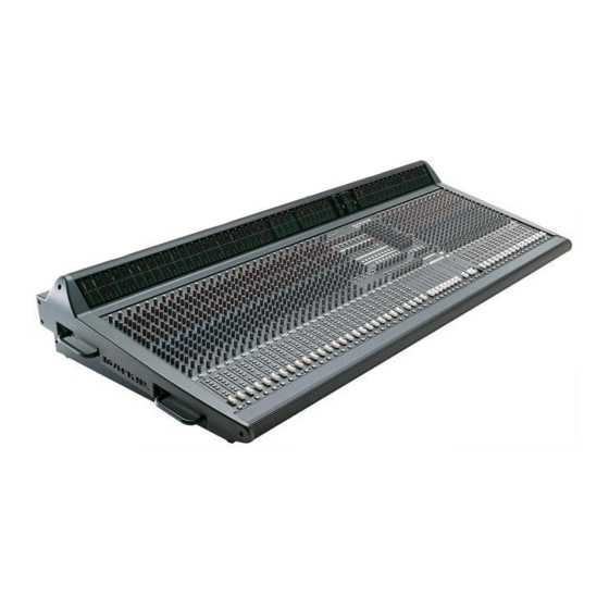
SYSTEM OVERVIEW THE SR40•8 IN A NUTSHELL This section provides a quick summary of the SR40•8’s major features. It is not intended to take the place of the owner’s manual. It is included here to help servicing technicians familiarize themselves with the SR40•8. MIXING Channel controls manipulate mic/line signals in this order: phantom power, trim, polarity, low cut filter, insert, EQ, mute, fader, pan, and assignment switches. -
Page 6: Stage Monitors & Effects
STAGE MONITORS & EFFECTS Every channel, as well as each of the four main aux returns (A1-A4), has eight aux send controls. Per channel, aux sends 1-4 can be switched to be post-fader (for effects sends) or pre-EQ/pre-fader (for stage monitors). Aux sends 5-8 have a similar switch, post-fader (for effects sends) or post-EQ/pre-fader (for stage monitors with EQ). -
Page 7: Talkback & Intercom
It allows all crew members to share a “party line,” so they may communicate at will, without having to toggle between send and receive. The Mackie SR40•8 takes that a step farther by allowing the engineer to join in at his/her discretion using the talkback microphone and phones outputs: No separate intercom headset is required for the engineer. -
Page 8: Ultra Mute Function Summary
™ ULTRA MUTE FUNCTION SUMMARY GENERAL • There are 9 Sets of 10 Groups each, for a total of 90 Groups. Up to 10 Groups can be active at a time within a Set. • There are 100 Snapshots (00-99). Only one Snapshot can be active at a time. •... - Page 9 CLEAR • In Group Mode, used to turn off all active Groups. Press and hold CLEAR for two seconds, then release to turn off all mutes on the console. This also indicates which Groups have been programmed (programmed Groups’ LEDs light up, unprogrammed Groups’ LEDs do not).
-
Page 10: Block Diagram
P H A N TO M D IR EC T O U T IN SE RT TR IM SE N D R ETU R N (BA L A N C E D ) P O LA R ITY M U TE M IC IN H PF H PF... - Page 11 IN SE R T TO M A TR I X IN SE N D R ETU R N (BA L A N C E D ) 3 K 3 M ID I IN U LTRA M U TE ª LIN K L F A D E R LE F T TA P E O U T (R = L+ R)
-
Page 12: Specifications
SPECIFICATIONS Noise Master Fader @ Unity, channel gains down -90dBu Master Fader @ Unity, channel gains @ Unity -86dBu ≥90dB Signal to Noise Ratio (ref +4) Total Harmonic Distortion Below 0.005% Crosstalk Channel Fader down, channels @ Unity -95dBu Channel muted, other channels @ Unity -95dBu Frequency Response 20Hz to 60kHz... -
Page 13: Circuit Theory
® ARCHITECTURE To keep thermal (Johnson) noise to a minimum, Mackie mixers employ VLZ architecture. In VLZ, or “Very Low Impedance”, architecture internal impedances are kept as low as practical in as many places as possible. Resistor values are scaled down by a factor of 3 to 4. -
Page 14: Input Circuitry
MIC/LINE PREAMP The SR40•8 uses Mackie’s famous low-noise, high headroom mic/line preamp design. The circuit has been revised since the version you may be familiar with from the earlier Mackie products. It’s topology is more elaborate than a standard discrete differential pair feeding an op-amp and has considerable performance advantages. -
Page 15: Solo Control Circuit
SOLO CONTROL CIRCUIT The SR40·8 has two interlinked solo systems. One serves all inputs: channels 1 to 40, aux returns A1-A4, B1-B4, and Tape inputs A and B. The other serves all outputs: subs 1-8, aux sends 1-8, left, center, right, and matrices A-D. Separate push-switches select between pre-fade-listen (PFL) and after-fade-listen/solo-in- place (AFL/SIP or just AFL). -
Page 16: Input Solo Logic
INPUT SOLO LOGIC At any input, depressing the solo switch connects 5V to the solo LED and to the solo control bus SOLO-CNTL-IP via a 4148 diode. The cathode of the solo LED connects to the flash bus FLASH via a 220-ohm current-limiting resistor. The flash bus is a current sink and only operates when an input has been soloed. -
Page 17: Other Matters
OTHER MATTERS Diode OR gate D4 and D5 drive comparator U2A, whose output goes low whenever SOLO-CNTL-IP or SOLO-CNTL-OP is high. U2A’s active low output drives the LCR-MUTE line, which controls shunt-series analog switches U1209A, U1209B, U1209C, and U1209D. Q2 operates as a 25 mA current source for the Rude Solo Light (RSL). Diode OR gate D6, D7 and D11 link both oscillators (U1A and U1B) to comparator U2D whose output drives transistor Q3 which shorts and unshorts the RSL, causing it to flash. -
Page 18: Clear Com™ Interface
The interface provides the standard Clear Com beltpack features: call button, call light, receive level control, and push-to-talk switch. Of course, like any Mackie product, there’s some new thinking going on to make your life easier. -
Page 19: Transmit Signal Path
TRANSMIT SIGNAL PATH The transmit signal path begins at the talkback microphone. The intercom interface takes the line level signal at U1705A and sends it to the intercom sub-system via JP1704 and JP1803. Analog switch U1801A passes the transmit audio when the INTERCOM button has been pressed. -
Page 20: Ignore Switch (Rev 6 Pcb)
IGNORE SWITCH (Rev 6 PCB) If the SR40·8 shares the intercom line with the lighting company, there is a high degree of activity on the line, which would ordinarily be distracting to the mix engineer. The ignore switch isolates the SR40·8 from the intercom line, while still allowing it to be accessible. When the IGNORE switch, SW1802, has been depressed, analog switch U1801B opens, disconnecting the headphone system from the intercom receive audio. - Page 21 CLEAR COM ™ JUMPER OPTIONS Name Description Procedure Default Setting Intercom pre- Makes talk level JP1704, cut trace Post fader. fader independent of between pins 2 R1741. and 3, jumper pins 1 and 2. Modify talk level Use with pre- JP1803, cut bypassed fader mod...
-
Page 22: Ultra Mute
ULTRA MUTE™ CIRCUIT DESCRIPTION ULTRA MUTE is a microprocessor based system that stores and recalls specific mute states on the SR40•8 console. The system uses a 12MHz 80C51 processor. The 80C51 CPU produces a 14 bit address. The lower 8 bits are latched by a 74HC573 from the multiplexed address/data bus. - Page 23 MUTE CONTROL BOARD AD0-AD7 PW R DIST PCB ™ ULTRAM U TE SIM PLIFIED SC HEM ATIC LATCH RS-232 74HC573 EPROM EPROM UART 27C128 6116 80C51 6850 A8-A13 M IDI IN ULTRA MUTE SERIAL D ATA MUTE BUS M IDI OUT SRAM 6116 NVRAM...
-
Page 24: Self Test Procedure
ULTRA MUTE SELF TEST PROCEDURE The following procedure tests the Ultra Mute system. Performing it will not erase any stored mute groups/scenes. Step Procedure Result / Verify Power off the console n/a (the console is off) Connect MIDI in to MIDI out, connect n/a (you accidentally burn your finger pins 2 and 3 on the data port soldering pins on an old DB9 plug) -
Page 25: Parts
PARTS QUICK PARTS M O N O C H A N N E L S M A IN A U X R E T U R N S P H A N T O M P W R B U T TO N , 7 6 0 -0 1 3 -0 0 S W IT C H , 5 0 0 -0 1 8 -0 0 T R I M T R I M... - Page 26 M A S T E R , 1 O F 2 P O W E R S T A T U S D I M M E R S F L I P A L L L E D 'S , 3 0 4 - 02 7 -0 2 50 K B PO T , 1 30 - 00 2 - 0 2 B U T TO N , 7 6 0- 0 1 3 - 0 0 K N O B , 7 6 0 - 0 4 8 - 0 4...
- Page 27 M A S T E R , 2 O F 2 R E C E I V E 5 0 K G PO T , 1 3 0 - 0 0 3 -0 2 K N O B , 7 60 -0 4 8- 0 1 I G N O R E B U T TO N , 7 6 0 - 0 1 3- 0 0 S W IT CH , 5 00 -0 1 8 - 0 0...
-
Page 29: Console Chassis Assembly
CONSOLE CHASSIS ASSEMBLY CHASSIS ASSEMBLY, DRAWING 1 OF 6 ITEM PART # DESCRIPTION 551-025-00 ARMREST 550-187-00 TOP PANEL 24 CH 550-189-00 TOP PANEL MASTER 550-188-00 TOP PANEL 16 CH 551-026-00 METER BRIDGE 550-196-00 STIFFENER 550-193-10 SIDE PANEL RIGHT 550-193-20 SIDE PANEL LEFT 700-046-09 SCREW SEMS 10-32X3/4 (HANDLES) 710-012-00... - Page 31 CHASSIS ASSEMBLY, DRAWING 2 OF 6 ITEM PART # DESCRIPTION 055-069-00 PCB ASSY. CHANNEL METER 055-076-00 PCB ASSY. MASTER METER 040-132-00 RIBBON CABLE 5C 74" 550-190-00 BACK PANEL 24 CH 550-192-00 BACK PANEL MASTER SECTION 550-191-00 BACK PANEL 16 CH 040-130-00 CABLE ASSY BLK 9"...
- Page 33 CHASSIS ASSEMBLY, DRAWING 3 OF 6 ITEM PART # DESCRIPTION 780-029-00 DISPLAY LENS 720-002-00 TAPE USED ON ABOVE 055-075-00 PCB ASSY. MUTE SWITCH 040-104-00 RIBBON CABLE ASSY. 34C 16" 040-015-00 RIBBON CABLE ASSY. 34C 10" 055-074-00 PCB ASSY. MASTER OUTPUT 040-093-00 RIBBON CABLE ASSY.
- Page 35 CHASSIS ASSEMBLY, DRAWING 4 OF 6 ITEM PART # DESCRIPTION 040-093-00 RIBBON CABLE ASSY. 40C 9.5" 040-102-00 RIBBON CABLE ASSY. 10C 15" 055-070-00 PCB ASSY. MONO POD 040-097-00 RIBBON CABLE ASSY. 40C 20" 040-098-00 RIBBON CABLE ASSY. 34C 27" 040-099-00 RIBBON CABLE ASSY.
- Page 37 CHASSIS ASSEMBLY, DRAWING 5 OF 6 ITEM PART # DESCRIPTION 055-077-00 PCB ASSY. POWER DIST 700-023-00 SCREW MACH 6-32X1/2 BLK 705-001-00 KEPNUT 6-32 DC POWER IN 700-028-00 SCREW SEMS 6-32X1/4 (POWER DIST) 706-017-00 STANDOFF 4-40 JACKSCREW (DSUB CONN) 710-008-00 SPLITLOCK WASHER # 4 (DSUB CONN) 055-101-00 PCB ASSY.
- Page 39 CHASSIS ASSEMBLY, DRAWING 6 OF 6 ITEM PART # DESCRIPTION 760-060-10 ENDCAP - RIGHT 700-039-00 SCREW MACH 10-32X1/2 (END CAP) 700-043-09 SCREW TF 10-32X3/4 (END CAP) 700-043-15 SCREW TF 10-32X1-1/2 (END CAP) 700-045-04 SCREW SEMS 10-32X3/8 (END CAP) 780-028-00 METER LENS 760-60-20 ENDCAP - LEFT 550-195-00...
-
Page 41: Power Supply Chassis Assembly
POWER SUPPLY CHASSIS ASSEMBLY PART # DESCRIPTION 040-010-00 CABLE RIBBON 22GA 7C 19IN (LED TO MAIN PCB) 040-112-00 CABLE DIS 18GA 1015 7C .156 9IN 040-113-00 CABLE DIS 18GA 1010 GRN/YEL 4IN LUG 040-114-00 CBL DIS 18GA 1010 BRN 11IN QD 040-115-00 CBL DIS 18GA 1010 BRN 18IN QDX2 040-116-00... -
Page 42: Console Parts List
SR40•8 SERVICE MANUAL CONSOLE PARTS LIST PART # DESCRIPTION PART # DESCRIPTION 040-036-00 DIS 22GA 1007 2C .10 12IN 115-373-00 RES MF .25W 1% 6K81 OHM 040-062-02 RIB 28GA 20C .100 18IN 130-002-02 POT RTY 50KB 9MM MNO H TN 040-062-03 RIB 28GA 20C .100 12IN 130-003-02... - Page 43 VERSION 1.0 PART # DESCRIPTION PART # DESCRIPTION 140-101-00 RES TF SM .1W 5% 15K OHM 212-004-00 CER 220PF 5% 50V NPO SM 140-103-00 RES TF SM .1W 5% 18K OHM 212-005-00 CER 20PF 5% 50V NPO SM 140-104-00 RES TF SM .1W 5% 20K OHM 212-006-00 CER 470PF 5% 50V NPO SM 140-105-00...
- Page 44 SR40•8 SERVICE MANUAL CONSOLE PARTS LIST (CONTINUED) PART # DESCRIPTION PART # DESCRIPTION 321-008-03 REG LM317L ADJ SM 401-001-28 IC SOCKET 28PIN DIP 321-009-00 REG LM337T ADJ 410-002-00 INSL SILPAD .007 SELF ADH 323-002-00 LM339D QUAD COMP SM 500-012-00 SW PUSH 4PDT V PCMNT LGCR 323-005-00 LP339M QUAD COMP SM 500-018-00...
- Page 45 VERSION 1.0 PART # DESCRIPTION PART # DESCRIPTION 701-002-00 SM B 6X1/4 PHP BLKZC 840-068-00 LBL EPROM - SR40/56.8 701-005-00 SM A-AB 6X1/4 PHP BLKZC 860-007-00 EPROM SOFTWARE - SR40.8 704-001-01 PEMNUT 6-32 .038 STL 704-001-02 PEMNUT 6-32 .054 STL 704-005-01 PEMNUT 10-32 .038 STL 704-023-03...
-
Page 46: Power Supply Parts List
SR40•8 SERVICE MANUAL POWER SUPPLY PARTS LIST PART # DESCRIPTION PART # DESCRIPTION 040-101-00 RIB 22GA 7C .100 19IN 301-005-00 DIO FAST RECOVERY FR602 040-112-00 DIS 18GA 1015 7C .156 9IN 302-005-00 DIO ZEN 1N4732A 5V .4X.3 040-118-00 POWER CORD FEMALE TO MALE 302-007-00 DIO ZEN 1N5234C 6.2V 2% 040-119-00... - Page 47 VERSION 1.0 PART # DESCRIPTION PART # DESCRIPTION 551-027-00 EXTR HEATSINK - SR40.8 PS 830-015-00 REG & WARR CARD - SR40.8 553-001-03 CRS 20GA 48 X 120 840-024-00 LBL DATE CODE 553-002-04 CRS 18GA 30 X 120 840-065-00 LBL SN SR40/56 PS AE 553-005-03 CRS 11GA 48 X 120 553-005-03...
-
Page 48: Connector Pinout And Location
CONNECTOR PINOUT AND LOCATION SR40•8 CHANNEL PCB CONNECTOR LOCATIONS MO N O C H A N N E L PC B 055-0 67-00 C O MP O N EN T SID E... - Page 49 SR40•8 CHANNEL PCB CONNECTOR PINOUT CONNECTS TO POD PCB P1 CONNECTS TO METER PCB J1 CONNECTS TO POD PCB J2 40 PIN CABLE 040-093-00 10 PIN CABLE 040-103-00 10 PIN CABLE 040-102-00 CH 1 IN + 1 2 CH 1 IN - CH 1 MTR 1 2 CH 2 MTR CH 1 DIR 1...
- Page 50 SR40•8 STEREO CHANNEL PCB CONNECTOR LOCATIONS ST ER EO C H A N N EL P C B 055-0 67-00 C O MP O N EN T SID E...
- Page 51 SR40•8 STEREO CHANNEL PCB CONNECTOR LOCATIONS MAIN BUS CONNECTS TO POD PCB J11 50 PIN CABLE 040-092-00 40 PIN CABLE 040-099-00 SUB 1 + 1 2 SUB 1 - A1 LEFT + 1 2 A1 LEFT - GND 3 4 SUB 2 + A1 LEFT GND 3 4 A1 RIGHT + SUB 2 - 5...
- Page 52 SR40•8 MASTER PCB CONNECTOR LOCATIONS / PINOUT CONNECTS TO POD PCB J2 J1 8 41 PIN CABLE 040-097-00 J1 0 J1 3 SUB 1 OUT 1 2 SUB 2 OUT SUB 3 OUT 3 4 SUB 4 OUT SUB 5 OUT 5 6 SUB 6 OUT J1 4 SUB 7 OUT 7...
- Page 53 SR40•8 MASTER PCB CONNECTOR PINOUT CONNECTS TO METER PCB J102 CONNECTS TO POD PCB J8 CONNECTS TO DIGI PCB J16 14 PIN CABLE 040-106-00 34 PIN CABLE 040-104-00 20 PIN CABLE 040-062-02 SUB 1 METER 1 2 SUB 2 METER LEFT OUT 1 2 RIGHT OUT 5V 1...
-
Page 54: Schematics / Pcb Layouts
The remainder of this manual contains schematics and PCB layouts for the SR40•8. Documents are organized in numeric order by Mackie part #. The schematics and PCB layouts are placed as close together as possible to reduce “page flipping fatigue syndrome”... - Page 55 SPEAKING MACKIE-EESE Some of the terminology and labeling used in the SR40•8 schematics may be confus- ing (or at least illogical) to those new to servicing Mackie products. Here are a few explanations. • “Mono Pod “ and “Master Pod” refer to the circuit boards at the rear of the console containing most of the jacks.
- Page 56 THE MIXER FIXER • MACKIE DESIGNS SERVICE NEWS THE MIXER FIXER • MACKIE DESIGNS SERVICE NEWS SR 40•8 +12V Power Supply Fuse Upgrade: Model: SR40/56•8 440W Power supplys Serial #: Prior to SN#AD14392 Effective 4/20/98 Symptom: No +12V Power LED’s or no power to the Little Light outlets.
- Page 57 THE MIXER FIXER • MACKIE DESIGNS SERVICE NEWS THE MIXER FIXER • MACKIE DESIGNS SERVICE NEWS SR 40•8 5-Volt Filter Capacitor Model: SR40•8 Serial #: Prior to SN # AD14392 Effective 8/11/97 Symptom: No symptoms, just improved supply filtering. Solution: Install one 47uf 25V cap (part #220-002-00) per each Mono Channel PCB’s...
- Page 58 THE MIXER FIXER • MACKIE DESIGNS SERVICE NEWS THE MIXER FIXER • MACKIE DESIGNS SERVICE NEWS SR 40•8 Clock Jumper Model: SR40•8 Serial #: Prior to SN#AD14392 Effective 6/1/97 Symptom: Digital clock noise in the PFL Solo bus. Solution: On the Mono Channel PCB cut and jump the trace pictured in Fig. 1...
- Page 59 THE MIXER FIXER • MACKIE DESIGNS SERVICE NEWS THE MIXER FIXER • MACKIE DESIGNS SERVICE NEWS SR 40•8 Solo Clock Noise Model: SR40•8 Serial #: Prior to SN# AD14392 Effective 5/8/97 Symptom: Digital clock noise in the PFL Solo bus.
- Page 60 THE MIXER FIXER • MACKIE DESIGNS SERVICE NEWS THE MIXER FIXER • MACKIE DESIGNS SERVICE NEWS SR 40•8 Digital Output PCB Clock Noise Mod Model: SR40•8 Serial #: Prior to SN# AD14392 Effective 7/1/97 Symptom: Clock noise in PFL bus.
- Page 61 THE MIXER FIXER • MACKIE DESIGNS SERVICE NEWS THE MIXER FIXER • MACKIE DESIGNS SERVICE NEWS SR 40•8 Power Supply Diode Failure Model: SR40 • 8 PSU (Power supply unit) Serial #: Not available. Very early production, probably only 10-20...
- Page 62 SR40•8 upgrade kit. (Prior to SN #AD14392) Dear Service Centers, Mackie Designs has recently created an upgrade kit for the SR40•8 Large Format Mixer. We have created a Mixer Fixer for each upgrade. On all SR 40•8 consoles that come in for service with serial number prior to AD14392 the following updates must be done.
- Page 63 THE MIXER FIXER • MACKIE DESIGNS SERVICE NEWS THE MIXER FIXER • MACKIE DESIGNS SERVICE NEWS SR 40 • 8 ULTRA MUTE Timing Error Model: SR40•8 Serial #: Prior to SN# AD14298 Effective 6/1/97 Symptom: Muting FETs don’t always follow mute LEDs when recalling snapshots.