Table of Contents
Advertisement
Advertisement
Table of Contents

Related Manuals for Motorola Astro APX Mobile 05 control head


Summary of Contents for Motorola Astro APX Mobile 05 control head
- Page 3 Motorola Trademark PMLN5592E Holdings, LLC and are used under license. All other trademarks are the property of their respective owners. © 2009–2011 by Motorola Solutions, Inc. All Rights Reserved. 10/11 1303 East Algonquin Road, Schaumburg, Illinois 60196, U.S.A. English...
-
Page 4: Menu Navigation
Direct radio-to-radio communication or On = Secure operation. Sending an Emergency Call (Trunking Only) communication through a repeater. Off = Clear operation. On = Direct Blinking = Receiving an encrypted voice Press Emergency button. Off = Repeater call. A tone sounds and the display alternates On = AES Secure operation. -
Page 5: Declaration Of Conformity
Per FCC CFR 47 Part 2 Section 2.1077(a) Responsible Party Name: Motorola Solutions, Inc. Address: Motorola Solutions, Inc., 1303 East Algonquin Road Schaumburg, IL60196, U.S.A. Phone Number: 1-800-927-2744 Hereby declares that the product: Model Name: APX 7500 / APX 6500 conforms to the following regulations: FCC Part 15, subpart B, section 15.107(a), 15.107(d) and section 15.109(a) - Page 6 Note: This equipment has been tested and found to comply with the limits for a Class B digital device, pursuant to part 15 of the FCC Rules. These limits are designed to provide reasonable protection against harmful interference in a residential installation.
-
Page 7: Table Of Contents
Disclaimer ......xi Contents Getting Started ......1 This User Guide contains all the information you need to use the APX™... - Page 8 General Radio Operation ....26 Accessing the Preprogrammed Functions ..9 Using the Menu Select Buttons ....9 Selecting a Zone .
- Page 9 Receiving and Making a Selective Call (Conventional Editing a Call Type ......51 Only) ........39 Scan Lists .
- Page 10 Sending an Emergency Alarm with Accessing the Drafts Folder ....74 Emergency Call ......61 Managing Sent Text Messages .
- Page 11 Editing the Coordinates of a Waypoint ..87 Auto Power Off Timer ..... . 95 Deleting a Single Saved Waypoint .
- Page 12 Appendix: Maritime Radio Use in the VHF Turning Off Non-Rearmable External Alarms . . . 105 Turning Off Rearmable External Alarms ..105 Frequency Range ..... 110 Using the Voice Announcement .
-
Page 13: Important Safety Information
RF energy exposure limits. Changes or modifications made to this device, not expressly For a list of Motorola-approved antennas and other approved by Motorola, could void the user's authority to accessories, visit the following website: operate this equipment. -
Page 14: Informations Importantes Sur La Sécurité
6881095C99) pour assurer le respect peuvent annuler le droit de l'utilisateur à utiliser cet équipement. des limites d'exposition à l'énergie RF. Pour obtenir une liste d'antennes et d'autres accessoires approuvés par Motorola, consultez le site Web : http://www.motorolasolutions.com/APX English... -
Page 15: Computer Software Copyrights
Laws in the written permission of Motorola. No part of this manual United States and other countries preserve for Motorola may be reproduced, distributed, or transmitted in any... - Page 16 Notes English...
-
Page 17: Getting Started
Notations Used in This Manual Getting Started Throughout the text in this publication, you will notice the use of Take a moment to review the following: WARNING, Caution, and Note. These notations are used to How to Use This User Guide ..... page 1 emphasize that safety hazards exist, and the care that must be Notations Used in This Manual . -
Page 18: Additional Performance Enhancement
APX mobile SecureNet allows user to perform secured communications on radios. an Analog or Motorola Data Communication (MDC) channel. The MDC OTAR feature will allow users to perform OTAR Dynamic System Resilience (DSR) activities on an MDC channel. -
Page 19: What Your Dealer/System Administrator Can Tell You
What Your Dealer/System Administrator Preparing Your Radio for Use Can Tell You Turning On the Radio ......page 4 Check with your dealer or system administrator, if the radio is to Validating Compatibility During Power Up. -
Page 20: Turning On The Radio
To turn off the radio, press the Power On/Off Button after the Turning On the Radio LEDs light up. Press the Power On/Off Button Validating Compatibility During Power Up briefly to power on the radio. The radio validates and updates the software and hardware of After a short time, the red, yellow Power On/ your control head(s) during power up. -
Page 21: Adjusting The Volume
Adjusting the Volume Identifying Radio Controls To increase the volume, Take a moment to review the following: rotate the Volume Knob Radio Parts and Controls ......page 6 clockwise. -
Page 22: Radio Parts And Controls
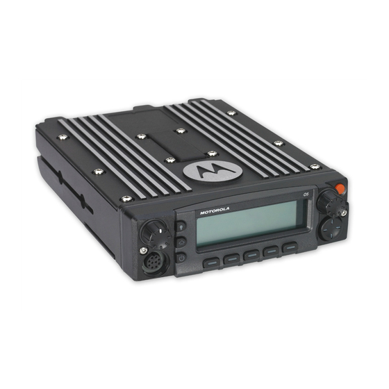
Radio Parts and Controls Navigation Button O5 Control Head and Microphone (Microphone) Cancel Button Data Feature Volume Knob Mode Knob Button* Dim Button Orange Button* Home Button Okay/Select Push-to-Talk Home Button (Microphone) Button ( ) (PTT) Button Power On/Off Button Keypad Accy No-Dot Buttons... -
Page 23: Programmable Features
Dynamic Priority (Conventional Only) – Allows any channel Programmable Features in a scan list (except for the Priority-One channel) to temporarily replace the Priority-Two channel. Any reference in this manual to a control that is “preprogrammed” means that the control must be programmed Emergency –... - Page 24 One Touch 1 – 4 – Launches a specific feature with one single Site Display (Trunking Only) – Views the current site or button-press. You can setup as much as four separately enable a site search for SmartZone operation. programmed buttons for four different features. Site Lock/Unlock (Trunking Only) –...
-
Page 25: Assignable Settings Or Utility Functions
Accessing the Preprogrammed Functions Assignable Settings or Utility Functions – Changes the display brightness. You can access various radio functions through one of the Front/Rear – Switches one of two control heads to be active at following ways: one time. •... -
Page 26: Using The Advance Programmable Buttons
Using the Advance Programmable Buttons Using the Navigation Buttons This feature is to help you to shorten the process of applying Home Button certain common features. button returns you to the home (default) display. In most Orange Button* cases, this is the current mode. For selected radio features, the button is also used to save user-edited radio settings or information before returning you to... -
Page 27: 4-Way Navigation Button
4-Way Navigation Button Volume Knob Use this button to scroll up, down, left or right. Use this Volume Knob to adjust the volume of the speakers by turning it clockwise or counterclockwise. Press and release one of the button to scroll from one entry to the next one. -
Page 28: Using The Keypad
Using the Keypad You can use the 3 x 4 alphanumeric keypad on the keypad microphone to access your radio’s features. The keypad functions in a manner similar to a standard telephone keypad when entering numeric digits. When the keypad is used to edit a list, each key can generate different characters of the alphabet. -
Page 29: Keypad Characters - Lowercase Mode
Keypad Characters – Lowercase Mode Number of Times Key is Pressed & “ ‘ Toggle between mixed case mode, uppercase mode, and lowercase mode. Space Toggle between numeric and letter mode. English... -
Page 30: Keypad Characters - Numeric Mode
Keypad Characters – Numeric Mode Number of Times Key is Pressed & “ ‘ Space Toggle between numeric and letter mode. English... -
Page 31: Keypad Characters - Hexadecimal Mode
Keypad Characters – Hexadecimal Mode Number of Times Key is Pressed Not applicable Not applicable English... -
Page 32: Push-To-Talk (Ptt) Button
Push-To-Talk (PTT) Button Identifying Status Indicators The PTT button on the side of the Your radio indicates its operational status through the following: microphone serves two basic Status Icons ....... . . page 17 purposes: Button Text Messaging Service (TMS) Icons . -
Page 33: Status Icons
Status Icons Monitor (Carrier Squelch) Selected channel is being monitored (during The liquid crystal display (LCD) of your radio shows the radio conventional operation only). status, text entries, and menu entries. In-Call User Alert The following are the icons that appear on the radio’s display. •... - Page 34 Vote Scan Enabled User Login Indicator (IP Packet Data) The vote scan feature is enabled. • On = User is currently associated with the radio. Secure Operation • Off = User is currently not associated with the • On = Secure operation. radio.
-
Page 35: Text Messaging Service (Tms) Icons
Text Messaging Service (TMS) Icons Read Message The selected text message in the Inbox has been This feature allows you to send and receive text messages. See read. Text Messaging Service (TMS) on page 66 for more Message Index information. Indicates the index of the current message the user is viewing. -
Page 36: Tms Menu Options
TMS Menu Options Priority Status and Request Reply • User is composing a message with a priority Menu Option Description/Function status and a request for a reply. Brings you to your incoming messages INBX • Messages in the Inbox folder are flagged with screen. -
Page 37: Led Indicator
LED Indicator Menu Option Description/Function CURR Deletes the current selected message. LED indicator shows the operational status of your radio. Selects to delete all the messages in the current folder. Red LED Deletes all the messages in the current Yellow LED folder. -
Page 38: Intelligent Lighting Indicators
Intelligent Lighting Indicators This feature temporary changes the radio’s display backlight color and the alert text background color to help signal that a radio event has occurred. Note: This feature must be preprogrammed by a qualified radio technician. Backlight Event When The radio initiates an emergency alarm or call. -
Page 39: Alert Tones
Alert Tones An alert tone is a sound or group of sounds. Your radio uses alert tones to inform you of your radio’s conditions. The following table lists these tones and when they occur. You Hear Tone Name Heard Radio Self Test Fail When radio fails its power-up self test. - Page 40 You Hear Tone Name Heard Valid Key-Press When correct key is pressed. Radio Self Test Pass When radio passes its power-up self test. Clear Voice At beginning of a non-coded communication. Short, Medium-Pitched Priority Channel When activity on a priority channel is received. Tone Received Emergency Alarm Entry...
- Page 41 You Hear Tone Name Heard Fast Ringing When system is searching for target of Private Call. Ringing Enhanced Call Sent When waiting for target of Private Call to answer the call. Phone Call Received When a land-to-mobile phone call is received. Gurgle Dynamic Regrouping (When the PTT button is pressed) a dynamic ID has been received.
-
Page 42: General Radio Operation
Selecting a Zone General Radio Operation A zone is a group of channels. Once you understand how your APX Mobile Radio is configured, you are ready to use your radio. Note: Your radio must be preprogrammed to allow you to use these features. -
Page 43: Selecting A Radio Channel
Selecting a Radio Channel Using Channel Search Button A channel is a group of radio characteristics, such as transmit/ This feature allows you to do a quick search for a specific receive frequency pairs. channel in the radio by key in the alias of the channel. If the name matches, your radio prompts the first found matched Use the following procedure to select a channel. -
Page 44: Using Mode Select Feature
Using Mode Select Feature Press the Menu Select button directly below CHSR once the entry is done to initiate searching. Mode Select allows a long press to save the radio’s current Press the Menu Select button directly below CNCL to exit. zone and channel to a programmable button, keypad button or a softkey;... -
Page 45: Saving A Zone And Channel To A Softkey
Saving a Zone and Channel to a Softkey Saving a Zone and Channel to a Keypad Button Five softkeys are available for you to save the frequent used All the programmable buttons and keypad digit 0 to 9 buttons zone and channel. allow you to save the frequent used zone and channel. -
Page 46: Receiving And Responding To A Radio Call
Receiving and Responding to a Radio Call Receiving and Responding to a Talkgroup Call To receive a call from a group of users, your radio must be Once you have selected the required channel and/or zone, you configured as part of that talkgroup. can proceed to receive and respond to calls. -
Page 47: Receiving And Responding To A Private Call (Trunking Only)
Press and hold the PTT button to talk. Release the PTT Receiving and Responding to a Private Call button to listen. (Trunking Only) Press to hang up and return to the Home screen. A Private Call is a call from an individual radio to another individual radio. -
Page 48: Receiving And Responding To A Telephone Call
Making a Radio Call Receiving and Responding to a Telephone Call This feature allows you to receive calls similar to standard You can select a zone, channel, subscriber ID, or talkgroup by phone calls from a landline phone. using: Note: If the feature inactivity timer is enabled, your radio •... -
Page 49: Making A Private Call (Trunking Only)
Procedure: Making a Private Call (Trunking Only) > < to TGRP and press the Menu Select button directly This feature allows you to send an individual Call Alert or page if below TGRP. there is no answer from the target radio. Your radio must be The display shows the last-selected talkgroup. -
Page 50: Making A Telephone Call
A telephone-type ringing sounds if the receiving unit is in Making a Telephone Call service. The display shows CALLING...<NUMBER> or This feature allows you to make calls similar to standard phone CALLING...<ALIAS>. calls to a mobile or landline phone. Hold the microphone vertically 1 to 2 inches (2.5 to 5.0 cm) Procedure: from your mouth. -
Page 51: Repeater Or Direct Operation
Repeater or Direct Operation Press and release the PTT button to dial the phone number. Hold the microphone vertically 1 to 2 inches (2.5 to 5.0 cm) The REPEATER operation increases the radio’s range by from your mouth. connecting with other radios through a repeater. The transmit When your call is answered, press the PTT button to talk. -
Page 52: Monitoring Features
Trunked Modes Only: Monitoring Features Press the PTT button. Radio users who switch from analog to digital radios often If you hear two, short, high-pitched tones, or if you hear no assume that the lack of static on a digital channel is an tone and the indicator lights steadily, then proceed with indication that the radio is not working properly. -
Page 53: Conventional Mode Operation
At Home mode where the default zone and channel are Conventional Mode Operation > < being displayed, button to MON. This feature allows you to monitor channel traffic on conventional channels by defeating the coded squelch. Thus Press the Menu Select button directly below MON you can to listen to another user active on the channel. -
Page 54: Advanced Features
Advanced Call Features Advanced Features Use this navigation guide to learn more about advanced Calling a Phone Not in the List features available with your radio: > < to PHON. Advanced Call Features ..... . . page 38 Multiple Control Head Features . -
Page 55: Receiving And Making A Selective Call (Conventional Only)
If 20 seconds pass before you press the Menu Select button Receiving and Making a Selective Call CALL directly below the , you will not respond privately to the call (Conventional Only) just received. Instead, you initiate a Selective Call. See Making This feature allows you to receive a call from or to call a specific a Selective Call on page 39. -
Page 56: Using The Talkgroup Call Feature (Conventional Operation Only)
Hold the microphone vertically 1 to 2 inches (2.5 to 5.0 cm) Selecting a Talkgroup from your mouth. Procedure: Press and hold the PTT button to start the Selective Call. > < to TGRP. The display shows the ID of the target radio. Press the Menu Select button directly below TGRP. -
Page 57: Sending A Status Call
When the dispatcher acknowledges, four tones sound and Sending a Status Call the display shows ACK RECEIVED. The radio returns to This feature allows you to send data calls to the dispatcher normal dispatch operation. about a predefined status. If no acknowledgment is received, a low-pitched tone Each status can have up to a 14-character name. -
Page 58: Requesting A Reprogram
Procedure: the radio returns to the Home screen. When your radio is dynamically regrouped, it automatically If the dispatcher does not acknowledge the reprogram switches to the dynamically regrouped channel. A “gurgle” request within six seconds, a low-pitched alert tone sounds tone sounds and the display shows the dynamically and the display shows NO ACKNOWLEDGE. -
Page 59: Multiple Control Head Features
Multiple Control Head Features Setting the Initial Control Head’s ID This feature allows you to setup the control head in the Front Panel Programming (FPP) mode. During the setup, the control Multiple Control Head Features heads are defined as Control Head Number 1, Control Head This feature allows a transceiver to control as many as four O5 Number 2, Control Head Number 3 and Control Head Number control heads on APX 7500 and, up to two O5 control heads on... -
Page 60: All Active Mode
Press the PTT button to initiate an intercom transmission. All Active Mode All control heads that are attached will receive the same The All Active mode enables all connected control heads intercom call. attached to the radio to operate concurrently with each other. The display of the control heads receiving the intercom call When you activate a feature on one control head, the rest of the shows the alias/ID number of the transmitting control head. - Page 61 The Volume knob, DIM button, Front/Rear (F/R) softkey and Follow the procedure below to change the command between Emergency button remain active on the inactive control head, the two control heads. while all other controls are disabled. Emergency footswitch and Procedure: VIP inputs remain active on the inactive control head.
-
Page 62: Contacts
Contacts Note: Your radio is preprogrammed with a number of contacts per Call Lists. Check with your dealer or system administrator for more information. This feature provides “address-book” capabilities on your radio. Each entry corresponds to an alias (name) or ID (number) that If the feature inactivity timer is enabled, your radio you use to initiate a call. - Page 63 Hold the microphone vertically 1 to 2 inches (2.5 to 5.0 cm) Press the Menu Select button directly below CNTS. from your mouth. > < to the required subscriber alias. Press the PTT button to initiate the call. During the call, the Press the Menu Select button directly below CNTS.
-
Page 64: Adding A New Contact Entry
> < Adding a New Contact Entry to {ADD NUMBER} and press the Menu Select button directly below SEL. The display shows TYPE 1 <DEFAULT Procedure: TYPE>. > < to CNTS. Press Menu Select button directly below EDIT. Press the Menu Select button directly below CNTS. The >... -
Page 65: Deleting A Contact Entry
Deleting a Contact Entry Adding a Contact to a Call List or Phone List Procedure: Procedure: > < > < to CNTS. to CNTS. Press the Menu Select button directly below CNTS. The Press the Menu Select button directly below CNTS. The entries are alphabetically sorted. -
Page 66: Editing A Contact In A Call List Or A Phone List
Press the Menu Select button directly below OK once you Editing a Contact in a Call List or a Phone List have finished. The display returns to the Edit Contact screen. Editing an Entry Alias Press the Menu Select button directly below DONE to save Procedure: your changes and return to the main screen for Contacts. -
Page 67: Editing A Call Type
Press * to add a space. Editing a Call Type Press 0 to toggle between mixed case mode, uppercase Procedure: mode, and lowercase mode. Press # to toggle between numeric and letter mode. > < to CNTS. Press the Menu Select button directly below OK once you Press the Menu Select button directly below CNTS. -
Page 68: Scan Lists
Scan Lists Editing the Scan List This feature lets you change scan list members and priorities. Scan lists are created and assigned to individual channels/ Procedure: groups. Your radio scans for voice activity by cycling through the channel/group sequence specified in the scan list for the current >... -
Page 69: Changing The Scan List Status
Press to exit scan list programming and return to the Press H to exit scan list programming and return to the Home screen. Home screen. See Viewing and Changing the Priority Status on page 53 for Viewing and Changing the Priority Status more information on how to add and/or change the priority of the currently displayed channel in the scan list. -
Page 70: Scan
Scan Turning Scan On While Disregarding the Squelch Code (Conventional Channels Only) This feature allows you to monitor traffic on different channels Procedure: by scanning a preprogrammed list of channels. > < to MON. Turning Scan On or Off Press the Menu Select button directly below MON. Procedure: The brief MONITOR ON display indicates that the radio is Press the preprogrammed Scan button. -
Page 71: Radio Programmed For Non-Talkback Scan
The radio does not begin scanning again for a predetermined Deleting a Nuisance Channel hang time after you release the PTT button, allowing the other If a channel continually generates unwanted calls or noise party to respond. If the other party responds within the hang (termed a “nuisance”... -
Page 72: Changing Priorities Status While Scan Is On
Changing Priorities Status While Scan is On Restoring Priorities in a Scan List While the radio is scanning, the dynamic priority change feature Procedure: allows you to temporarily change any channel in a scan list To restore the original channel priorities in a scan list, do one of (except for the Priority-One channel) to the Priority-Two the following: channel. -
Page 73: Call Alert Paging
Call Alert Paging Receiving a Call Alert Page Procedure: This feature allows your radio to work like a pager. When you receive a Call Alert page Even if other users are away from their radios, or if they are You hear four repeating alert tone and the green LED blinks. unable to hear their radios, you can send them an individual Call Alert page. -
Page 74: Sending A Call Alert Page
Press the Menu Select button directly below OK to return to Sending a Call Alert Page the main screen for Contacts. Note: If the feature inactivity timer is enabled, your radio automatically exits the feature when your radio is left idle long enough for the time to expire. -
Page 75: In-Call User Alert
Press the Menu Select button directly below OK to return to Emergency Operation the main screen for Contacts. The Emergency feature is used to indicate a critical situation. In-Call User Alert If the Orange button is preprogrammed to send an emergency signal, this signal overrides any other communication over the You can enable and disable voice transmission, if needed. -
Page 76: Sending An Emergency Alarm
Sending an Emergency Alarm Sending an Emergency Call (Trunking Only) This feature allows you to send a data transmission, which Procedure: identifies the radio sending the emergency, to the dispatcher. Press preprogrammed Emergency button. Procedure: A tone sounds and the display alternates EMERGENCY and Press the preprogrammed Emergency button. -
Page 77: Sending An Emergency Alarm With Emergency Call
A high-pitched tone sounds, indicating that the alarm has Sending an Emergency Alarm with Emergency been received by the trunked system’s central controller. Call A dispatcher acknowledgment (four high-pitched tones) This feature allows you to send an Emergency Alarm to another follows, accompanied by an ACK RECEIVED display. -
Page 78: Sending A Silent Emergency Alarm
Sending a Silent Emergency Alarm Special Considerations for Emergencies • This feature allows you to send an Emergency Alarm to another If you press the emergency button while in a channel that has radio without any audio or visual indicator. no emergency capability, a low-pitched tone sounds. -
Page 79: Automatic Registration Service (Ars)
Advanced Features Selecting or Changing ARS Mode Automatic Registration Service (ARS) Procedure: This feature provides an automated data application registration After the zone you want is displayed, toggle until the display for the radio. When you turn on the radio, the device shows the required channel. -
Page 80: Accessing The User Login Feature
Accessing the User Login Feature Logging In as a User This feature allows you as the user to be associated with the Procedure: radio. With this association, every data application (Example: > < to USER. Text Messaging Service) takes on a friendly username. Press the Menu Select button directly below USER. -
Page 81: Logging Out
The maximum PIN length is 4 digits. The PIN number will Logging Out appear as asterisks. Once the data application registration is completed, you can log Menu Select Press the button directly below LOGN. out. In ARS server mode, the display shows the User Login Procedure: Indicator icon, the ID, IN PPROGRESS and CNCL. -
Page 82: Text Messaging Service (Tms)
Text Messaging Service (TMS) Accessing TMS Feature Note: If the feature inactivity timer is enabled, your radio This feature allows you to send and receive text messages. The automatically exits the feature when your radio is left maximum length of characters for a text message is 200. idle long enough for the time to expire. -
Page 83: Composing And Sending A New Text Message
Press 0 to toggle between mixed case mode, uppercase Composing and Sending a New Text Message mode, and lowercase mode. Note: During the uppercase and lowercase mode, multi- Press # to toggle between numeric and letter mode. tapping the keys only scrolls through the letters. For Press the Menu Select button directly below OPTN once the example, A->B->C, a->b->c. -
Page 84: Sending A Quick Text Message
Press the Menu Select button below SEND to send the Sending a Quick Text Message message. Quick Text messages are messages that are predefined and usually consist of messages that are used most frequently. Press the PTT button to send the message. Each Quick Text message has a maximum length of 50 The display shows the SEND MESSAGE screen and characters. - Page 85 > Press the Menu Select button below SEND to send the Press to move one space to the right. message. Press the Menu Select button directly below DEL to delete any unwanted characters. Press the PTT button to send the message. Press * to add a space.
-
Page 86: Using The Priority Status And Request Reply Features
Using the Priority Status and Request Reply Appending or Removing a Request Reply to a Text Features Message Procedure: Before sending your message, you can append a priority After the outgoing message is composed (see Composing and message and/or a request reply to your message. Sending a New Text Message on page 67 for more information): Appending or Removing a Priority Status to a Text... -
Page 87: Removing A Priority Status And A Reply Request From A Text Message
> < Managing Text Messages to RQRP and press the Menu Select button directly below RQRP to request for a reply. Receiving a Text Message The priority status and reply status icons appear beside the normal message icon on the label bar. Note: When you receive a message that is flagged with the ”Request Reply”... -
Page 88: Viewing A Text Message From The Inbox
Viewing a Text Message from the Inbox While on the review message screen, press the Menu Select RPLY BACK button directly below , or to access the option. The Inbox can hold up to thirty (30) messages. • Select RPLY to reply the message. -
Page 89: Replying To A Received Text Message
> Replying to a Received Text Message Press to move one space to the right. Press the Menu Select button below DEL to delete any Note: The original date and time stamp, address and unwanted characters. message content is automatically appended to the Press * to add a space. -
Page 90: Accessing The Drafts Folder
Managing Sent Text Messages Accessing the Drafts Folder This folder stores the messages that were saved previously. Once a message is sent to another radio, it is saved in the Sent The Drafts folder can hold up to 10 messages. The oldest draft folder. -
Page 91: Sending A Sent Text Message
OPTN > Press the Menu Select button directly below , or Press to move one space to the right. BACK to access the option. Press the Menu Select button below DEL to delete any unwanted characters. • OPTN Select to send to the message. Press * to add a space. -
Page 92: Deleting Text Messages
> < to scroll through the messages. Unlike other forms of security, Motorola digital encryption Press the Menu Select button directly below DEL to view the provides signaling that makes it virtually impossible for others to delete options. -
Page 93: Loading The Group Encryption Keys
When the key has been loaded successfully, the radio Using the Multikey Feature sounds a short tone for single-key radios. This feature allows the radio to be equipped with different encryption keys and supports the DES-OFB algorithm. Loading the Group Encryption Keys There are two types of multikey: Procedure: •... -
Page 94: Selecting An Encryption Key (Conventional Only)
Selecting an Encryption Key (Conventional Only) Enabling Secure Transmission Procedure: Procedure: > < > < to KEY. to SEC and press the Menu Select button directly below SEC. The display shows and the current key if Press the Menu Select button directly below KEY. The multi-key has been enabled. -
Page 95: Selecting A Keyset
The radio exits keyset selection and returns to the Home Selecting a Keyset screen. This feature allows you to select one or more groups of several encryption keys from among the available keys stored in the Erasing the Selected Encryption Keys radio. -
Page 96: Requesting An Over-The-Air Rekey
Requesting an Over-the-Air Rekey MDC Over-the-Air Rekeying (OTAR) Page This feature allows to view or define MDC Over-the-Air This feature, also known as OTAR, allows the dispatcher to reprogram the encryption keys in the radio remotely. The Rekeying (OTAR) features.It is applied only when operating in dispatcher performs the rekey operation upon receiving a rekey secure encrypted mode and only for conventional request from the user. -
Page 97: Hear Clear
The Global Positioning System (GPS) Hear Clear There are two components of Hear Clear. This feature uses information from the Global Positioning System (GPS) satellites orbiting the Earth to determine the Companding: Reduces the channel noise, e.g. OTA transmission, that is approximate geographical location of your radio, expressed as predominantly present in UHF2 and 900 MHz channel with latitude and longitude. -
Page 98: Enhancing Gps Performance
• Under any other metal or concrete roof or structure Enhancing GPS Performance • Between tall buildings or under dense tree-cover Sometimes, the GPS feature may be unable to complete a location calculation successfully. You then see a message • In temperature extremes outside the operating limits of your indicating that your radio cannot connect to enough visible radio... -
Page 99: Accessing The Outdoor Location Feature
The radio also stores four (4) preprogrammed waypoints. These Accessing the Outdoor Location Feature coordinates cannot be deleted. Note: An ON menu key may be present on the location menu if it is preprogrammed by the dealer or system Programmable Waypoints Preprogrammed Waypoints administrator. - Page 100 > < Once the location coordinates are fixed, the display shows to check the longitude, time and date of the last the current latitude. Toggle to see the longitude, time and successful location fix. date. Press the Menu Select button directly below OPTN. The location coordinates are updated automatically every five seconds while the location signal is present.
-
Page 101: Saving A Waypoint
Press the Menu Select button directly below OK once you Saving a Waypoint are done. Procedure: The display shows SAVED AS <WAYPOINT NAME>. While in the current location display: Press the Menu Select button directly below OPTN. The display shows SAVED AS HOME. >... -
Page 102: Editing The Alias Of A Waypoint
Press the Menu Select button directly below SEL. Editing the Alias of a Waypoint > < Procedure: to desired waypoint. While in the current location display: Press the Menu Select button directly below OPTN. The display shows VIEW. Press the Menu Select button directly below OPTN. >... -
Page 103: Editing The Coordinates Of A Waypoint
Press the Menu Select button directly below CNCL to return Press the Menu Select button below EDIT to change the to the Waypoints main screen. number/coordinates. The display shows <WAYPOINT NAME> UPDATED. A blinking cursor appears in the EDIT LOCATION screen. <... -
Page 104: Deleting A Single Saved Waypoint
Deleting a Single Saved Waypoint Deleting All Saved Waypoints Procedure: Procedure: Press the Menu Select button directly below OPTN. While in the current location display: > < Press the Menu Select button directly below OPTN. to WAYPOINTS and press the Menu Select button directly below SEL. -
Page 105: Measuring The Distance And Bearing From A Saved Waypoint
Measuring the Distance and Bearing from a Saved Using the Location Feature While in Emergency Waypoint Mode When the Emergency feature is activated by pressing the Procedure: emergency button, the radio exits the Location menu and While in the current location display: returns to the home (default) display so that you can see which Press the Menu Select button directly below OPTN. -
Page 106: Trunking System Controls
Trunking System Controls Going Out-of-Range OUT OF RANGE when your radio goes out of the range of the system, it can no longer lock onto a control channel. Using the Failsoft System Procedure: The failsoft system ensures continuous radio communications during a trunked system failure. -
Page 107: Smartzone
® SmartZone Locking and Unlocking a Site ® This feature allows your radio to lock onto a specific site and not The SmartZone feature extends communications beyond the roam among wide-area talkgroup sites. This feature should be reach of a single-trunked site (antenna location) when operating used with caution, since it inhibits roaming to another site in a in a SmartZone system. -
Page 108: Viewing And Changing A Site
Viewing and Changing a Site Changing the Current Site This feature allows you to view the number of the current site or Procedure: force your radio to change to a new one. Press and hold down the preprogrammed Site Search button. -
Page 109: Trunked Announcement
Trunked Announcement Initiating an Announcement The announcement capability allows you to make If your radio has been programmed to allow announcement announcements to the entire user group, as well as monitor calls: talkgroup calls and other announcements. Procedure: Announcement calls are handled in two different ways, Press the Mode Knob to locate the announcement-group depending on the trunked central controller configuration. -
Page 110: Ignition Switch Options
Ignition Switch Options Required This option allows the user to power on the radio only if the This feature allows the user to select the radio’s functionality Ignition is present. The radio can be powered off either through based on the Ignition State of the radio user’s vehicle. The Power button press or when Ignition is lost. -
Page 111: Emergency Power Up
Note: While "Ignition" is not present, the radio powers-off Auto Power Off Timer with a radio-user Power Off button / knob selection if Auto Power Off feature powers off the radio when no user the radio was powered-up with an Emergency Power actions occur during a preprogrammed length of time. -
Page 112: Utilities
If the feature inactivity timer is enabled, your radio automatically Utilities exits the feature when your radio is left idle long enough for the time to expire. You will hear the Menu Inactive Exit Tone upon Viewing Recent Calls List feature exit. -
Page 113: Selecting A Radio Profile
The display shows LOW POWER and the low power icon. Press the Menu Select button directly below EXIT to exit the screen without making any changes. The display shows HIGH POWER and the high power icon. The radio returns to the Home screen. The profile name on Selecting a Radio Profile the Home screen indicates the current selected radio profile. -
Page 114: Turning Keypad Tones On Or Off
Turning Keypad Tones On or Off Turning Voice Mute On or Off You can enable and disable keypad tones as needed. You can enable and disable voice muting of the affiliated trunking talkgroup or selected conventional channel as needed. Procedure: Procedure: Press the preprogrammed Keypad Mute button to turn the Press the preprogrammed Voice Mute button to turn the feature... -
Page 115: Using The Time-Out Timer
Using the Time-Out Timer Using the Conventional Squelch Operation Features This feature turns off your radio’s transmitter. You cannot transmit longer than the preset timer setting. This feature filters out unwanted calls with low signal strength or channels that have a higher than normal background noise. If you attempt to do so, the radio automatically stops your Procedure: transmission, and you hear a talk-prohibit tone. -
Page 116: Analog Options
Using the PL Defeat Feature Analog Options Tone Private Line (PL), Digital Private-Line (DPL), and carrier This feature allows you to override any coded squelch (DPL or PL) that might be preprogrammed to a channel. The radio also squelch can be available (preprogrammed) per channel. unmutes to any digital activity on a digital channel. -
Page 117: Using The Smart Ptt Feature (Conventional Only)
Using the Smart PTT Feature (Conventional Only) Accessing General Radio Information Smart PTT is a per-personality, programmable feature used in Your radio contains information on the following: conventional radio systems to keep radio users from talking • Radio Information over other radio conversations. •... -
Page 118: Viewing Ip Information
• • Viewing IP Information DVRS DSP Version (only DVRS CP Version (only when when DVRS is available) DVRS is available) This feature displays the device name, IP address, and status of • • Model Number Serial Number your radio. •... -
Page 119: Viewing Control Assignments
Using Optional External Alarms (Horn and Lights) Viewing Control Assignments This feature displays the programmable radio functions All control heads can be equipped for external alarms (horn and assigned to the controls of your radio for the currently selected lights) that are activated when a Call Alert page, Private channel. -
Page 120: Using Permanent Horn And Lights
Using Permanent Horn and Lights Changing the Selected Alarms If Permanent Horn and Lights is enabled, horn and lights will Procedure: automatically be turned on when the radio powers up. Press the Menu Select button directly below H/L until the display shows the required alarm. -
Page 121: Receiving A Call While Alarms Are Turned On
Receiving a Call While Alarms are Turned On Turning Off Rearmable External Alarms When you receive a call with the Alarms turned on: Procedure: Press the Menu Select button directly below CALL, PAGE Procedure: or PHON to turn off the external alarm(s) and place you You hear the vehicle’s horn sounds for four seconds, and/or directly in that feature. -
Page 122: Using The Voice Announcement
Note: Voice announcements support certain number of zone- Using the Voice Announcement channel, but not all. This feature enables the radio to audibly indicate the current feature mode, Zone or Channel the user has just assigned. This Seek advice from your dealer or qualified technician for audio indicator can be customized per customer requirements. -
Page 123: Helpful Tips
Note: Pressing this preprogrammed playback button will Helpful Tips always enable the voice feature to announce in High priority. Caring for Your Radio......page 107 All the three programmable buttons at the side of the Cleaning the External Surface of the Radio . -
Page 124: Cleaning The External Surface Of The Radio
If your radio is locked up or the display shows FAIL 01/09, turn Cleaning the External Surface of the the radio off and then back on. If this does not correct the Radio condition, take the radio to a qualified radio technician for service. -
Page 125: Accessories
Highlights for the Accessories Accessories GPS only antenna is only used in either a single band UHF The accessory link below is for the family of products for APX. or 700/800 application where the Public Safety Microphone Not all accessories are FCC certified for operation with all APX (PSM) is used with the corresponding PSM antenna. -
Page 126: Appendix: Maritime Radio Use In The Vhf Frequency Range
4 “WE ARE LOCATED AT _______________________.” Appendix: Maritime Radio Use in the State the position of the vessel in distress, using any VHF Frequency Range information that will help responders to locate you, e.g.: • latitude and longitude • bearing (state whether you are using true or magnetic Take a moment to review the following: north) Special Channel Assignments. -
Page 127: Operating Frequency Requirements
Table A-1: VHF Marine Channel List (Continued) Operating Frequency Requirements Frequency (MHz) Channel A radio designated for shipboard use must comply with Federal Number Transmit Receive Communications Commission Rule Part 80 as follows: 156.100 160.700 • on ships subject to Part II of Title III of the Communications 156.150 160.750 Act, the radio must be capable of operating on the 156.800... - Page 128 Table A-1: VHF Marine Channel List (Continued) Table A-1: VHF Marine Channel List (Continued) Frequency (MHz) Frequency (MHz) Channel Channel Number Number Transmit Receive Transmit Receive 157.200 161.800 156.925 161.525 157.250 161.850 156.975 161.575 157.300 161.900 157.025 161.625 157.350 161.950 157.075 161.675 157.400...
-
Page 129: Glossary
Controller monitors and directs the operations of the Automatic Registration Service trunked repeaters. ASTRO 25 Motorola standard for wireless digital A group of characteristics such as transmit/ Trunking trunked communications. Channel receive frequency pairs, radio parameters, and encryption encoding. - Page 130 Term Definition Term Definition Codeplug A feature that allows communications to take place even though the central A visual tracking marker (a blinking line) Cursor controller has failed. Each trunked repeater that indicates a location on the display. Failsoft in the system transmits a data word Displayed by the radio after three failed informing every radio that the system has attempts to unlock the radio.The radio must...
- Page 131 Term Definition Term Definition Check channel activity through menu Private A feature that lets you have a private entries. If the channel is clear, you hear (Conversation) conversation with another radio user in the static. If the channel is in use, you hear Call talkgroup.
- Page 132 Term Definition Term Definition Any digital P25 traffic having the correct The automatic sharing of communications Selective Switch Network Access Code and the correct Trunking paths between a large number of users talkgroup. (see Conventional). Special electronic circuitry, added to the Trunking A scan list that includes talkgroups that are receiver of a radio, that reduces, or cuts off,...
-
Page 133: Commercial Warranty And Service
Product manufactured by MOTOROLA. MOTOROLA assumes no Commercial Warranty and Service obligations or liability for additions or modifications to this warranty unless made in writing and signed by an officer of MOTOROLA. Limited Warranty Unless made in a separate agreement between MOTOROLA and the original end user purchaser, MOTOROLA does not warrant the installation, maintenance or service of the Product. - Page 134 Product for which it is and insurance prepaid, to an authorized warranty service location. specified. Warranty service will be provided by MOTOROLA through one of its H)Freight costs to the repair depot. authorized warranty service locations. If you first contact the I) A Product which, due to illegal or unauthorized alteration of the company which sold you the Product (e.g., dealer or...
- Page 135 VI. PATENT AND SOFTWARE PROVISIONS: MOTOROLA will have no liability with respect to any claim of patent infringement which is based upon the combination of the Product or MOTOROLA will defend, at its own expense, any suit brought parts furnished hereunder with software, apparatus or devices not...
- Page 136 Motorola two- way radio dealer. For more information about ESP, contact the Motorola Radio Support Center, 2204 Galvin Drive, Elgin, IL 60123, 1-800-227-6772.