Table of Contents
Advertisement
Quick Links
Vespa would like to thank you
for choosing one of its products. We have prepared this booklet to help you to get the very best from your scooter. Please read it carefully before riding
the scooter for the first time. It contains information, tips and precautions for using your scooter. It also describes features, details and devices to assure
you that you have made the right choice. We believe that if you follow our suggestions, you will soon get to know your new vehicle and it will serve you
well for a long time to come. This booklet forms an integral part of the scooter; should the scooter be sold, it must be transferred to the new owner.
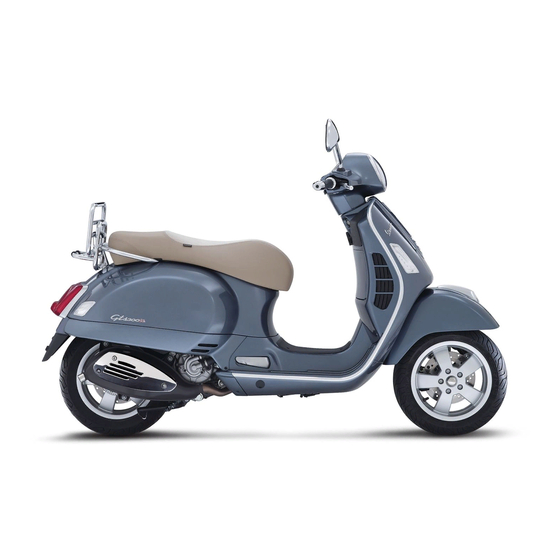
Vespa GTS 250
Ed. 2
Advertisement
Table of Contents
Troubleshooting

Related Manuals for VESPA GTS 250


Summary of Contents for VESPA GTS 250
- Page 1 Vespa would like to thank you for choosing one of its products. We have prepared this booklet to help you to get the very best from your scooter. Please read it carefully before riding the scooter for the first time. It contains information, tips and precautions for using your scooter. It also describes features, details and devices to assure you that you have made the right choice.
- Page 2 The instructions given in this booklet are intended to provide a clear, simple guide to using your scooter; details are also given of routine maintenance procedures and regular checks that should be carried out on the vehicle at an Authorised PIAGGIO Dealer or Service Centre. The booklet also contains instructions for simple repairs.
- Page 3 Personal safety Failure to completely observe these instructions will result in serious risk of personal injury. Safeguarding the environment Sections marked with this symbol indicate the correct use of the vehicle to prevent dam- aging the environment. Vehicle intactness The incomplete or non-observance of these regulations leads to the risk of serious damage to the vehicle and sometimes even the invalidity of the guarantee.
-
Page 5: Table Of Contents
INDEX VEHICLE..................Stand..................34 Dashboard................Automatic transmission............. 34 Analogue instrument panel............Safe driving................35 Clock..................10 Rear rack.................. 37 Digital lcd display..............10 MAINTENANCE................39 Setting the total and trip odometers........11 Engine oil level................40 Key switch................. 11 Engine oil level check............40 Locking the steering wheel............ - Page 6 Warnings................... 78 PROGRAMMED MAINTENANCE..........81 Scheduled maintenance table........... 82...
- Page 7 Vespa GTS Chap. 01 Vehicle...
- Page 8 Dashboard (01_01) A = Starter button B = Engine block Run-Off switch C = Throttle control D = Front brake lever E = Instrument panel F = Rear brake control lever 01_01 G = Horn button H = Turn indicator switch I = Light switch Analogue instrument panel (01_02) A = Digital dashboard...
- Page 9 01_02...
-
Page 10: Clock
Clock (01_03) Located on the instrument panel, it displays hours and minutes with 1 to 24 hour time. Besides hours and minutes, month and day can also be displayed with the «T» button. In order to adjust the above mentioned functions, operate button «U». 01_03 Digital lcd display (01_04) A = Odometer... -
Page 11: Setting The Total And Trip Odometers
Setting the total and trip odometers (01_05) The «TRIP» button displays the total and partial kilometres covered when pressed repeatedly for less than 1 second. It resets the trip odometer when pushed more than 3 seconds. Push the «TRIP» button again to return to total odometer value. 01_05 Key switch (01_06) LOCK = ignition disabled, extractable key, mechanical antitheft device enabled. -
Page 12: Releasing The Steering Wheel
Releasing the steering wheel Reinsert the key and turn it to «OFF». CAUTION DO NOT TURN THE KEY TO «LOCK» OR «OFF» WHILE RIDING. Switch direction indicators (01_07) Lever towards "S" = Left turn indicator is switched on; Lever towards "D" = Right turn indicator is switched on; The lever returns automatically to position "0"... -
Page 13: Horn Button
Horn button (01_08) Push the «C» button to sound the horn. 01_08 Light switch (01_09) 0 = Low beam and side light 1 = High beam and side light 01_09... -
Page 14: Start-Up Button
Start-up button (01_10) Starter button "G" 01_10 Engine stop button (01_11) 0 = OFF 1 = RUN 01_11 The immobilizer system In order to enhance theft protection, the scooter is equipped with a «PIAGGIO IM- MOBILIZER » electronic engine locking device that is activated automatically when the starter key is removed. -
Page 15: Keys
Keys (01_12, 01_13, 01_14) Two types of keys come with the vehicle. The red-handgrip key "A" is the "MASTER" key. Only a single copy of this key is supplied, which is necessary to program all your other keys and for your dealer to perform some maintenance operations. For this reason it is advised that it be used only in exceptional circumstances. -
Page 16: Immobilizerdevice Enabled Indicator Led
Immobilizerdevice enabled indicator led (01_15) The operation of the «PIAGGIO IMMOBILIZER» system is signalled by a blinking indicator light, «I» (see the «Analogue dashboard» section). To prevent the battery from discharging, the indicator led automatically shuts down after 48 hours of uninterrupted operation. In the event of a malfunction to the system, the indicator led provides diagnostic in- formation to your Authorised Piaggio Service Centre through its blinking patterns. -
Page 17: Operation
01_15 Operation Every time the starter key is removed in the "OFF" or "LOCK" position, the safety system activates the immobilizer system. Turning the key to "ON" disables the engine lock, provided that the safety system recognises the code transmitted by the key. If the code is not recognised, turn the key first to "OFF"... -
Page 18: Programming The Immobilizer System
be started, contact an Authorised Piaggio Service Centre, which is provided with the electronic equipment required to detect and repair the system. When additional keys are required, please note that data storage (up to 7 keys max.) must be done on all keys, both new ones and existing ones. Take your scooter to an Authorised Piaggio Service Centre carrying with you the red-handgrip key and all the blue keys in your possession. - Page 19 Intermediate step - blu key Within ten seconds after pulling out the red key, insert the black key and promptly turn it to «ON». After 1-3 seconds, turn the key to "OFF" again and pull it out. In this way, a maximum of 3 blue keys can be programmed by repeating the above procedure and keeping the indicated times.
-
Page 20: Accessing The Fuel Tank
Accessing the fuel tank (01_16, 01_17, 01_18) With the key set to «OFF» or «ON», or with engine on, it is possible to electrically open the saddle by pressing the button «C». If the saddle opening system does not work, operate the emergency lever «A». -
Page 21: Opening The Saddle
Opening the saddle (01_19, 01_20) With the key set to «OFF» or «ON», or with engine on, it is possible to electrically open the saddle by pressing button «C». If the electric opening does not work, use the emergency lever "A". When the key is set to «LOCK» the saddle cannot be opened. 01_19 01_20 Identification (01_21, 01_22, 01_23) -
Page 22: Rear Top Box Opening
CAUTION BE REMINDED THAT ALTERING IDENTIFICATION REGISTRATION NUMBERS CAN LEAD TO SERIOUS PENAL SANCTIONS (IMPOUNDING OF THE VEHICLE, ETC.). 01_22 01_23 Rear top box opening (01_24) Insert the key into the switch and press down until the glove compartment opens. If the switch is set to "LOCK", turn the key to "OFF"... - Page 25 Vespa GTS Chap. 02...
-
Page 26: Checks
Checks Before using the vehicle, check: 1. There is enough fuel in the fuel tank. 2. The correct fluid level for front and rear brakes. 3. That tyres are properly inflated. 4. The correct functioning of tail lights, headlamp, turn indicators, stop light and license plate light. - Page 27 DO NOT ALLOW PETROL TO COME INTO CONTACT WITH HOT ENGINE OR ANY PLASTIC PARTS. CAUTION PETROL DAMAGES THE PLASTIC PARTS OF THE BODYWORK. CAUTION USING OILS OTHER THAN THOSE RECOMMENDED CAN SHORTEN THE LIFE OF THE ENGINE. CAUTION DO NOT USE THE VEHICLE TO THE COMPLETE EXHAUSTION OF THE FUEL; IN THE EVENT THAT THIS SHOULD OCCUR, DO NOT ATTEMPT TO START THE ENGINE.
- Page 28 02_02...
-
Page 29: Tyre Pressure
Tyre pressure (02_03) Check the tyre pressure and wear periodically (roughly every 500 km). The tyres are equipped with wear indicators; the tyres should be replaced as soon as these indica- tors become visible on the tyre tread. Also check that tyres do not show cuts on the sides or irregular tread wear;... -
Page 30: Shock Absorbers Adjustment
Shock absorbers adjustment (02_04) The preloading of the springs can be adjusted to 4 positions using the ring nut located in the lower part of the shock absorbers and the specific spanner supplied. Position 1: minimum preload: driver only Position 2 medium preloading: driver only Position 3 medium preloading: rider and passenger Position 4: maximum preloading: driver, passenger, and luggage. -
Page 31: Running In
Running in (02_05) WARNING DURING THE FIRST 1000 KM DO NOT RIDE THE VEHICLE OVER 80% OF ITS MAXIMUM SPEED. AVOID TWISTING THE THROTTLE GRIP FULLY OR KEEP- ING A CONSTANT SPEED ALONG LONG SECTIONS OF ROAD. AFTER THE FIRST 1000 KM, GRADUALLY INCREASE SPEED UNTIL REACHING THE MAX- IMUM PERFORMANCE. -
Page 32: Precautions
CAUTION DO NOT START-UP THE ENGINE IN CLOSED AREAS BECAUSE EXHAUST GASES ARE TOXIC. 02_07 Precautions CAUTION NEVER STRESS THE ENGINE AT LOW TEMPERATURES IN ORDER TO AVOID POSSIBLE DAMAGE. BE CAREFUL NEVER TO EXCEED THE MAXIMUM SPEED WHILE RUNNING DOWNHILL, IN ORDER TO AVOID DAMAGING THE ENGINE. IN ANY CASE, IN ORDER TO PRESERVE THE ENGINE FROM PROLONGED EX- CESSIVE REVOLUTIONS, THE REVOLUTION LIMITER WILL BE ACTIVATED IF THE ENGINE SPEED EXCEEDS THE ESTABLISHED THRESHOLD. -
Page 33: Difficult Start Up
Difficult start up In the rare case of flooding the engine, to facilitate start-up, it is possible to try to put the vehicle into action with the gas hand grip partially or completely open. It is however necessary, once the engine is started, to take your vehicle to an Authorised Service Centre to determine the cause of this problem and to re-establish the vehicle proper functioning. -
Page 34: Automatic Transmission
Stand (02_10) CENTRE STAND Push with your foot on the centre stand's fork «F» while lifting the vehicle backward, holding onto the handlebar. SIDE STAND With your foot push the projection of the stand «L » in order to open it and at the same time lean the vehicle on you. -
Page 35: Safe Driving
1. Do not continue riding in such conditions. 2. Let the clutch cool down with the engine at idle speed for a few minutes. 02_12 Safe driving (02_13, 02_14) WARNING SOME SIMPLE TIPS ARE PROVIDED BELOW THAT WILL ENABLE YOU TO USE YOUR SCOOTER ON A DAILY BASIS IN GREATER SAFETY AND WITH MORE PEACE OF MIND. - Page 36 4. Do not brake hard on a wet surface, on dirt tracks or on any slippery road surface. 5. If you have to brake, use both brakes in order to divide the braking action between both wheels. 6. Avoid starting off by mounting the scooter while it is still resting on its stand. In any case, the rear wheel should not be turning when in comes into contact with the ground, in order to avoid abrupt departures.
-
Page 37: Rear Rack
Rear rack (02_15) When riding without packages on the luggage racks, set the corresponding retainer latch "A" as shown in the photograph. WARNING Maximum admissible load: 6 kg 02_15... -
Page 39: Maintenance
Vespa GTS Chap. 03 Maintenance... -
Page 40: Engine Oil Level
Engine oil level In 4T engines, engine oil is used to lubricate the distribution elements, main bearings and thermal group. An insufficient quantity of oil can cause serious damage to the engine itself. In all four-stroke engines, a loss of efficiency in oil performance and consumption should be considered normal. -
Page 41: Warning Light (Insufficient Oil Pressure)
Warning light (insufficient oil pressure) The vehicle is equipped with a warning light that lights up when the key is turned to the «ON». However, this light should switch off once the engine has been started. If the light comes on while braking, at idle speed or while turning a corner, it is necessary to check the oil level and top it up if required. - Page 42 WARNING EXCESSIVE OIL LEVEL AT TOP-UPS CAN LEAD TO SCALE FORMATION AND VEHICLE MALFUNCTION. CAUTION USED OILS CONTAIN SUBSTANCES HARMFUL TO THE ENVIRONMENT. FOR OIL CHANGE, CONTACT AN AUTHORISED PIAGGIO SERVICE CENTRE, AS THEY ARE EQUIPPED TO DISPOSE OF USED OILS IN AN ENVIRONMENTALLY FRIENDLY AND LEGAL WAY.
-
Page 43: Hub Oil Level
Hub oil level (03_04, 03_05) Check the oil in the rear hub. To check the rear hub oil level, proceed as follows: 1) Park the scooter on level ground and rest it on its stand. 2) Unscrew dipstick «A», wipe it clean with a cloth, reinsert it and tighten completely. 3) Pull out the dipstick and check that the oil level is above the first notch from the bottom. - Page 44 CAUTION WHEN REPLACING THE HUB OIL DO NOT LET THE OIL COME INTO CONTACT WITH THE REAR BRAKE DISC. CAUTION FOR OIL REPLACEMENT, CONTACT ANY AUTHORISED SERVICE CENTRE AS THEY ARE EQUIPPED TO DISPOSE OF USED OILS IN AN ENVIRONMENTALLY FRIENDLY AND LEGAL WAY.
-
Page 45: Tyres
Tyres (03_06) Check tyre pressure periodically (about every 500 km). Tyres feature wear indicators; replace tyres as soon as these indicators become visible on the tyre tread. Also check that the tyres do not show signs of splitting at the side or irregular tread wear; if this occurs, go to an authorised workshop or at least to a workshop equipped to perform the replacement. -
Page 46: Spark Plug Dismantlement
Spark plug dismantlement (03_07, 03_08) Proceed as follows: 1. lift the saddle «A» 2. lift the helmet compartment «B» and reach into the spark plug with your hand; 3. disconnect cap of the spark plug HV wire; 4. unscrew the spark plug using the spark plug spanners «D» supplied; 5. -
Page 47: Removing The Air Filter
Removing the air filter (03_09, 03_10, 03_11, 03_12) Proceed as follows: 1. unscrew the fixing screw «A». 2. unscrew the nut «B» under the body. 3. remove the left side fairing. 4. remove the helmet compartment; 5. unscrew the fixing screws «C» that can be reached once the helmet compartment 03_09 has been removed;... -
Page 48: Cooling Fluid Level
Oil for air filter sponge Mineral oil with specific additives for increased adhesiveness 03_12 Cooling fluid level (03_13, 03_14) Engine cooling is carried out by a forced-circulation coolant system; the cooling system holds about 2.100 ÷ 2.150 l of coolant- a mixture of 50% de-ionised water and 50% ethylene-glycol antifreeze solution and corrosion inhibitors. - Page 49 If the fluid is near the minimum level, top-up only when the engine is cold. If it is nec- essary to top up the coolant frequently, or if the expansion tank is completely dry, you should look for the cause in the cooling system. Have the cooling system checked at an Authorised Piaggio Service Centre.
-
Page 50: Checking The Brake Oil Level
Checking the brake oil level (03_15, 03_16) The brake reservoirs are located on top of the pumps, underneath the handlebar cover (front on the rhs and rear on the left). The procedures for the inspection of the brake fluid level for the front and rear brakes are identical. Proceed as follows: 1. -
Page 51: Battery
CAUTION AVOID CONTACT OF BRAKE FLUID WITH EYES, SKIN, AND CLOTHING. IN CASE OF CONTACT, RINSE WITH WATER. THE BRAKING CIRCUIT FLUID IS HYGROSCOPIC, THAT IS, IT ABSORBS HUMIDITY FROM THE SURROUNDING AIR. IF THE HUMIDITY IN THE BRAKING FLUID EXCEEDS A CERTAIN VALUE, IT WILL LEAD TO INEFFICIENT BRAKING. -
Page 52: Use Of A New Battery
ER TOO MUCH IN ORDER TO AVOID DANGEROUS LEAKAGE OF BATTERY ELECTROLYTE CAUTION ELECTROLYTE CONTAINS SULPHURIC ACID: AVOID CONTACT WITH EYES, SKIN AND CLOTHES. IN THE CASE OF ACCIDENTAL CONTACT, RINSE WITH 03_18 ABUNDANT OF WATER AND CONSULT A DOCTOR. WARNING SPENT BATTERIES ARE HARMFUL FOR THE ENVIRONMENT. -
Page 53: Long Periods Of Inactivity
WARNING SPENT BATTERIES ARE HARMFUL FOR THE ENVIRONMENT. COLLECTION AND DISPOSAL SHOULD BE CARRIED OUT IN COMPLIANCE WITH CURRENT REGULATIONS. Long periods of inactivity Battery performance will decrease if the vehicle is not used for a long time. This is the result of the natural phenomenon of battery discharging plus residual absorption by vehicle components with constant power consumption. -
Page 54: Fuses
WARNING DO NOT DISCONNECT THE BATTERY CABLES WITH THE ENGINE RUNNING, THIS CAN CAUSE PERMANENT DAMAGE TO THE VEHICLE ELECTRONIC CON- TROL UNIT. WARNING SPENT BATTERIES ARE HARMFUL FOR THE ENVIRONMENT. COLLECTION AND DISPOSAL SHOULD BE CARRIED OUT IN COMPLIANCE WITH CURRENT REGULATIONS. - Page 55 CAUTION MODIFICATIONS OR REPAIRS TO THE ELECTRICAL SYSTEM, PERFORMED INCORRECTLY OR WITHOUT STRICT ATTENTION TO THE TECHNICAL SPEC- IFICATIONS OF THE SYSTEM, CAN CAUSE ERRORS IN FUNCTIONING AND RISK OF FIRE. USES General Position on fuse box: 1 Fuse: 30A Protected circuits: General Ignition ECU Fuse box arrangement: 2...
- Page 56 Dashboard lighting, intercom and Fuse box arrangement: 5 anti-theft device pre-wiring Fuse capacity: 10 A Protected circuits: Dashboard lighting, intercom and anti-theft device pre-wiring High and low-beam lights, horn Fuse box arrangement: 6 Fuse capacity: 7,5 A Protected circuits: High and low- beam lights, horn High and low-beam lights, electric Fuse box arrangement: 7...
- Page 57 Protected circuits: Front and rear side lights, dashboard lighting 03_20 03_21...
- Page 58 03_22 03_23 03_24...
-
Page 59: Front Light Group
03_25 Front light group (03_26, 03_27, 03_28, 03_29, 03_30) To remove the headlight assembly, proceed as follows: 1: remove the riding mirrors. 2: remove screw «A» from the front grille. 3: remove the front handlebar cover fixing screw, «B». 4: remove the rear handlebar cover fixing screw, «C». 5: Detach the front handlebar cover. - Page 60 N.B. IF MISTING IS NOTICED ON THE INSIDE OF THE HEADLAMP GLASS, THIS DOES NOT INDICATE A FAULT AND IS RELATED TO THE HUMIDITY AND/OR TO LOW TEMPERATURES. THE PHENOMENON SHOULD QUICKLY DISAPPEAR WHEN THE LIGHT IS SWITCHED ON. THE PRESENCE OF DROPS OF WATER, ON THE OTHER HAND, COULD INDI- CATE THAT WATER IS INFILTRATING.
-
Page 61: Headlight Adjustment
Headlight adjustment (03_31, 03_32) Proceed as follows: 1. Place the vehicle in running order and with the tyres inflated to the prescribed pres- sure, on a flat surface 10 m away from a white screen situated in a shaded area, making sure that the longitudinal axis of the scooter is perpendicular to the screen;... -
Page 62: Rear Optical Unit
Rear optical unit (03_34) Remove screw «A» to remove the rear headlight assembly. Access to taillight bulbs, stop light bulb and license plate bulb. To reassemble, repeat the operation in the reverse order. N.B. IF MISTING IS NOTICED ON THE INSIDE OF THE HEADLAMP GLASS, THIS DOES NOT INDICATE A FAULT AND IS RELATED TO THE HUMIDITY AND/OR TO LOW TEMPERATURES. -
Page 63: Rear-View Mirrors
Rear-view mirrors Adjust the mirrors by applying slight pressure to the side of the mirror to move it to the desired position. Front and rear disc brake (03_36, 03_37) The brake disc and pad wear is automatically compensated, therefore it has no effect on the functioning of the front and rear brakes. -
Page 64: Puncture
CAUTION THE PRESENCE OF SAND, MUD, SNOW MIXED WITH SALT, ETC. ON THE ROAD, CAN DRASTICALLY REDUCE THE DURATION OF THE BRAKE PADS. IN ORDER TO AVOID THIS, WE RECOMMEND WASHING THE VEHICLE FRE- QUENTLY WHEN RIDING IN THESE ROAD CONDITIONS. Puncture (03_38) The vehicle is equipped with Tubeless tyres (without inner tube). -
Page 65: Periods Of Inactivity
Periods of inactivity (03_39) We recommend carrying out the following operations: 1. Clean the scooter thoroughly and then cover it with a canvas; 2. With the engine off and the piston in the bottom dead centre position, remove the spark plug, and pour into its hole 1 t0 2 cc of the recommended oil. Operate the starter button 1-2 times for roughly 1 second to turn the engine over slowly, then insert the spark plug again;... - Page 66 WARNING IF THE SCOOTER IS USED ON DUSTY ROADS IT IS NECESSARY TO SERVICE THE TRANSMISSION COVER FILTER SPONGE MORE FREQUENTLY. CAUTION DETERGENTS CAN POLLUTE WATER. THE VEHICLE MUST BE WASHED AT A WASH STATION EQUIPPED WITH A SPECIAL WATER PURIFICATION SYSTEM. WARNING THE USE OF A HIGH-PRESSURE WATER JET IS STRONGLY DISCOURAGED FOR ANY ENGINE CLEANING OPERATION;...
- Page 67 CLOTHS SOAKED IN PETROL, DIESEL OIL OR KEROSENE FOR CLEANING THE PAINTED OR PLASTIC SURFACES SO AS NOT TO DAMAGE THE LUSTRE FINISH OR ALTER THE MECHANICAL PROPERTIES. STARTING FAILURE Emergency switch in «OFF» Set the switch back to «ON» Fuse blown Replace the blown fuse and have the vehicle checked by an...
- Page 68 LACK OF COMPRESSION Loose spark plug. Screw in the spark plug tightly Cylinder head loose, piston gas Contact an Authorised Service rings worn. Centre. Valve stuck Contact an Authorised Service Centre. HIGH CONSUMPTION AND LOW PERFORMANCE Air filter blocked or dirty. Clean with water and shampoo and impregnate with petrol and specific oil (section «Removing the air...
- Page 69 INEFFICIENT SUSPENSIONS Shock absorber fault, oil leak, end Contact an Authorised Service buffer damaged; shock absorber Centre. preloading incorrectly set IRREGULAR AUTOMATIC TRANSMISSION Variator rollers and/or driving belt Contact an Authorised Service damaged Centre.
-
Page 71: Technical Data
Vespa GTS Chap. 04 Technical data... - Page 72 ECHNICAL DATA Engine Single-cylinder, four-stroke Bore x stroke 72 x 60 mm Cubic capacity 244.29 cm³ Compression ratio 10.5 - 11.5 : 1 Ignition advance (before TDC) variable (integrated into the ignition system) Spark plug CHAMPION RG 4 PHP Max. speed 120 km/h Valve clearance intake: 0.10 mm...
- Page 73 Lubrication Engine lubrication with lobe pump (inside crankcase) controlled by a chain with double filter: mesh and paper. Cooling Forced fluid circulation, with engine driven pump; 3-way thermostat to pump intake. Transmission Automatic expandable pulley variator with torque server, V belt, automatic centrifugal dry clutch, gear reduction unit and transmission compartment with...
- Page 74 Chassis Stamped plate supporting body. Kerb weight 151 ± 5 kg Maximum admitted weight ~ 340 kg Petrol tank ~ 9.2 l (approximate value) Reserve 2÷2.5 l (approximate value) Engine oil Capacity: 1.3 l (dry) ; 1.2 l (when changing oil and filter) Rear hub oil Capacity approximately 250 cc Cooling system...
- Page 75 04_01...
-
Page 76: Kit Equipment
Kit equipment One box-spanner for spark plugs; one twin screwdriver; one special spanner for ad- justing the rear shock absorber. The tools are arranged in the front case. -
Page 77: Spare Parts And Accessories
Vespa GTS Chap. 05 Spare parts and accessories... - Page 78 Warnings (05_01) WARNING TO PREVENT ACCIDENTS AND TO GUARANTEE PROPER STABILITY, PER- FORMANCE AND SAFETY, RIDE THE VEHICLE VERY CAREFULLY WHEN IT IS FITTED WITH ACCESSORIES OR WITH UNUSUAL LOADS. WARNING 05_01 IT IS ALSO RECOMMENDED THAT "ORIGINAL PIAGGIO SPARE PARTS" BE USED, AS THESE ARE THE ONLY ONES OFFERING YOU THE SAME QUALITY GUARANTEE AS THOSE INITIALLY FITTED ON THE SCOOTER.
- Page 79 WARNING NEVER RIDE THE SCOOTER EQUIPPED WITH ACCESSORIES (TOP BOX AND/ OR WINDSHIELD) AT A SPEED HIGHER THAN 100 km/h. THE SCOOTER CAN BE RIDDEN AT A HIGHER SPEED WITHOUT THE ACCES- SORIES MENTIONED BEFORE WITHIN THE LIMITS ESTABLISHED BY LAW. IF THERE SHOULD BE NON-PIAGGIO ACCESSORIES INSTALLED, OR AN AB- NORMAL LOAD, OR IF THE SCOOTER IS NOT IN A GENERALLY GOOD CON- DITION, OR WHENEVER WEATHER CONDITIONS DEMAND IT, SPEED SHOULD...
- Page 81 Vespa GTS Chap. 06 Programmed maintenance...
- Page 82 Scheduled maintenance table (06_01) Adequate maintenance is fundamental to ensuring long-lasting, optimum operation and performance of your vehicle. To this end, a series of checks and maintenance operations (at the owner's expense) have been suggested, which are included in the summary table on the following page. Any minor faults should be reported without delay to an Authorised Service Centre or Dealer without waiting until the next scheduled service to solve it.
- Page 83 km x 1,000 Coolant * Engine oil Hub oil Brake pads Sliding blocks / variable speed rollers Tyre pressure and wear Vehicle road test Suspensions Steering I: CHECK AND CLEAN, ADJUST, LUBRICATE OR REPLACE IF NECESSARY. C: CLEAN, R: REPLACE, A: ADJUST, L: LUBRICATE * Replace every 2 years RECOMMENDED PRODUCTS TABLE Product...
- Page 84 Product Description Specifications AGIP GP 330 Grease for brake levers, throttle White calcium complex soap-based spray grease with NLGI 2; ISO-L-XBCIB2 AGIP CITY HI TEC 4T Engine oil SAE 5W-40, API SL, ACEA A3, JASO MA Synthetic oil AGIP BRAKE 4 Brake fluid FMVSS DOT 4 Synthetic fluid AGIP PERMANENT SPEZIAL...
- Page 85 TABLE OF CONTENTS Turn indicators: 62 Tyre pressure: 29 Air filter: 47 Fuel: 20 Light switch: 13 Tyres: 45 Fuses: 54 Battery: 51, 52 Maintenance: 39, 81, 82 Brake: 50, 63 Headlight: 61 Mirrors: 63 Horn: 13 Hub oil: 43 Clock: 10 Saddle: 21 Scheduled maintenance: 82...
- Page 86 The descriptions and illustrations given in this publication are not binding. While the basic specifications as described and illustrated in this manual remain unchanged, PIAGGIO-GILERA reserves the right, at any time and without being required to update this publication beforehand, to make any changes to components, parts or accessories, which it considers necessary to improve the product or which are required for manufacturing or con- struction reasons.
- Page 87 WORKSHOP MANUAL 633577 Vespa GTS 250 I.E.
- Page 88 WORKSHOP MANUAL Vespa GTS 250 I.E. The descriptions and illustrations given in this publication are not binding. While the basic specifications as described and illustrated in this booklet remain unchanged, PIAGGIO-GILERA reserves the right, at any time and without being required to update this publication beforehand, to make any changes to components, parts or accessories, which it considers necessary to improve the product or which are required for manufacturing or construction reasons.
- Page 89 WORKSHOP MANUAL Vespa GTS 250 I.E. This workshop manual has been drawn up by Piaggio & C. Spa to be used by the workshops of Piaggio- Gilera dealers. This manual is addressed to Piaggio service mechanics who are supposed to have a basic knowledge of mechanics principles and of vehicle fixing techniques and procedures.
- Page 91 INDEX OF TOPICS CHAR HARACTERISTICS TOOL OOLING MAIN AINTENANCE TROUBL ROUBLESHOOTING ELE SYS LECTRICAL SYSTEM ENG VE NGINE FROM VEHICLE NGINE INJEC NJECTION SUSP USPENSIONS BRAK SYS RAKING SYSTEM COOL SYS OOLING SYSTEM CHAS HASSIS PRE DE DELIVERY TIME...
- Page 93 INDEX OF TOPICS CHAR HARACTERISTICS...
-
Page 94: Safety Rules
Vespa GTS 250 I.E. Characteristics This section describes the general specifications of the vehicle. Rules This section describes general safety rules for any maintenance operations performed on the scooter. Safety rules - If work can only be done on the vehicle with the engine running, make sure that the premises are well ventilated, using special extractors if necessary;... - Page 95 Vespa GTS 250 I.E. Characteristics Vehicle identification Chassis prefix: ZAPM45100000 ÷ 1001 Engine prefix: M451M ÷ 1001 Dimensions and mass DIMENSIONS AND MASS Specification Desc./Quantity Total loadless weight 151 ± 5 kg Width (to hand grips) 755 mm Length 1930 mm...
-
Page 96: Electrical System
Vespa GTS 250 I.E. Characteristics Engine DATA Specification Desc./Quantity Type single-cylinder, four-stroke and four liquid-cooled valves Timing system single overhead camshaft chain driven on the left- hand side, three-arm rocking levers set up with threaded set screw Bore 72 mm... -
Page 97: Wheels And Tyres
Vespa GTS 250 I.E. Characteristics Specification Desc./Quantity Fuses 1: 30A - 1: 15A - 3: 10A - 4: 7,5A - 1: 3A Generator alternating current Frame and suspensions FRAME AND SUSPENSIONS Specification Desc./Quantity Type Unitised body made of stamped plate... -
Page 98: Tightening Torques
Vespa GTS 250 I.E. Characteristics Tightening Torques GRUPPO STERZO Name Torque in Nm Upper steering ring nut 35 ÷ 40 Lower steering ring nut 12 - 14 Handlebar fixing screw 45 ÷ 50 (The two screws must be tightened to the prescribed torque after having done so with the rear wheel axle nut. - Page 99 Vespa GTS 250 I.E. Characteristics Name Torque in Nm rear wheel axle nut. Safety locks: see «Pre-deliv- ery Operations» ) FRENO POSTERIORE Name Torque in Nm Brake fluid pump - hose fitting 20 ÷ 25 Brake fluid pipe-calliper fitting 20 ÷ 25 Rear disc tightening bolt 11 ÷...
-
Page 100: Assembly Clearances
Vespa GTS 250 I.E. Characteristics Name Torque in Nm Clutch unit nut on driven pulley 45 ÷ 50 Drive pulley nut 75 ÷ 83 Transmission cover screws 11 ÷ 13 Driven pulley shaft nut 54 ÷ 60 Rear hub cap screws 24 ÷... - Page 101 Vespa GTS 250 I.E. Characteristics Cylinder - piston assy. ENGINE COUPLING CATEGORY Name Initials Cylinder Piston Play on fitting Cylinder 72.01 ÷ 72.017 71.953 ÷ 71.960 0.050 - 0.064 Cylinder 72.017 ÷ 72.024 71.960 ÷ 71.967 0.050 - 0.064 Piston 72.024 ÷...
- Page 102 Vespa GTS 250 I.E. Characteristics CRANKSHAFT/ CRANKCASE AXIAL CLEARANCE Name Description Dimensions Initials Quantity Half-shaft, trans- 16.6 +0-0.05 D = 0.20 - 0.50 mission side Flywheel side half- 16.6 +0-0.05 D = 0.20 - 0.50 shaft Connecting rod 18 -0.10 -0.15 D = 0.20 - 0.50...
- Page 103 Vespa GTS 250 I.E. Characteristics Measurement "A" to be taken is a value of piston re-entry, it indicates by how much the plane formed by the piston crown falls below the plane formed by the top of the cylinder. The further the piston falls inside the cylinder, the less the base gasket to be applied (to recover the compression ratio) and vice versa.
- Page 104 Vespa GTS 250 I.E. Characteristics Products RECOMMENDED PRODUCTS TABLE Product Description Specifications AGIP ROTRA 80W-90 Rear hub oil SAE 80W/90 Oil that exceeds the requirements of API GL3 specifi- cations AGIP CITY HI TEC 4T Oil to lubricate flexible transmis-...
- Page 105 INDEX OF TOPICS TOOL OOLING...
- Page 106 Vespa GTS 250 I.E. Tooling APPROPRIATE TOOL Stores code Description 001330Y Tool for fitting steering seats 001467Y017 Bell for bearings, outside Ø 39 001467Y014 Extraction pliers for ø 15 mm bearings 005095Y Engine support 002465Y Pliers for circlips 006029Y Punch for fitting fifth wheel seat...
- Page 107 Vespa GTS 250 I.E. Tooling Stores code Description 020021Y Front suspension service tool 020036Y Punch 020038Y Punch 020055Y Wrench for steering tube ring nut 020074Y Support base for checking crank- shaft alignment 020150Y Air heater support TOOL - 3...
- Page 108 Vespa GTS 250 I.E. Tooling Stores code Description 020151Y Air heater 020193Y Oil pressure gauge 020262Y Crankcase splitting strip 020263Y Sheath for driven pulley fitting 020306Y Punch for assembling valve seal rings 020329Y Mity-Vac vacuum operated pump TOOL - 4...
- Page 109 Vespa GTS 250 I.E. Tooling Stores code Description 020330Y Stroboscopic light for timing con- trol 020331Y Digital multimeter 020332Y Digital rev counter 020333Y Single battery charger 020334Y Multiple battery charger TOOL - 5...
- Page 110 Vespa GTS 250 I.E. Tooling Stores code Description 020335Y Magnetic support for dial gauge 020357Y 32 x 35 mm adaptor 020359Y 42 x 47 mm adaptor 020360Y 52 x 55 mm adaptor 020363Y 20 mm guide 020364Y 25 mm guide...
- Page 111 Vespa GTS 250 I.E. Tooling Stores code Description 020365Y 22 mm guide 020375Y 28 x 30 mm adaptor 020376Y Adaptor handle 020382Y Valve cotters equipped with part 012 removal tool 020382Y011 adapter for valve removal tool TOOL - 7...
- Page 112 Vespa GTS 250 I.E. Tooling Stores code Description 020393Y Piston fitting band 020412Y 15 mm guide 020423Y driven pulley lock wrench 020424Y Driven pulley roller casing fitting punch 020426Y Piston fitting fork TOOL - 8...
- Page 113 Vespa GTS 250 I.E. Tooling Stores code Description 020431Y Valve oil seal extractor 020434Y Oil pressure control fitting 020441Y 26 x 28 mm adaptor 020444Y Tool for fitting/ removing the driv- en pulley clutch 020456Y Ø 24 mm adaptor 020477Y...
- Page 114 Vespa GTS 250 I.E. Tooling Stores code Description 020483Y 30 mm guide 020489Y Hub cover support stud bolt set 494929Y Exhaust fumes analyser 020428Y Piston position check support 020460Y Scooter diagnosis and tester 020621Y H.V. cable extraction adapter TOOL - 10...
- Page 115 Vespa GTS 250 I.E. Tooling Stores code Description 020481Y Control unit interface wiring 001467Y035 Bearing housing outside diame- ter 47 mm 020626Y Driving pulley lock wrench 001467Y013 Pliers to extract ø 15 mm bear- ings 020627Y Flywheel lock wrench 020467Y...
- Page 116 Vespa GTS 250 I.E. Tooling Stores code Description 020454Y Tool for fitting piston pin stops (200 - 250) 020622Y Transmission-side oil guard punch 020480Y Petrol pressure check set 020244Y 15 mm diameter punch 020115Y Ø 18 punch 020271Y Tool for removing-fitting silent...
- Page 117 Vespa GTS 250 I.E. Tooling Stores code Description 020638Y 250 I. E. ENGINE - ABS SOFT- WARE 020469Y Reprogramming kit for scooter diagnosis tester TOOL - 13...
- Page 118 Vespa GTS 250 I.E. Tooling TOOL - 14...
- Page 119 INDEX OF TOPICS MAIN AINTENANCE...
-
Page 120: Maintenance Chart
Vespa GTS 250 I.E. Maintenance Maintenance chart EVERY 2 YEARS Action Coolant - change Brake fluid - change AFTER 1,000 KM Action Safety locks - check Throttle lever - adjustment Engine oil - change Electrical system and battery - check... - Page 121 Vespa GTS 250 I.E. Maintenance Action Engine oil - level check/top-up Brake pads - check condition and wear Driving belt - replacement AT 20,000 KM; 40,000 KM; 80,000 KM 150' Action Spark plug - replacement Throttle lever - adjustment Air filter - clean...
-
Page 122: Checking The Spark Advance
Vespa GTS 250 I.E. Maintenance Action Air filter - cleaning Air filter belt compartment - check Engine oil - change Valve clearance - check Electrical system and battery - check Coolant level - check Brake fluid level - check Engine oil - replacement... -
Page 123: Spark Plug
Vespa GTS 250 I.E. Maintenance - Refit the plastic cap on the flywheel cover. - Adjust the spark gap to the contact position (no reference mark visible) and install it on engine be- tween the spark plug and spark plug cap... - Page 124 Vespa GTS 250 I.E. Maintenance -Adjust the distance if necessary by bending the side electrode very carefully. In case of anomaly (as described before) replace the spark plug with another of the recommended type; - Fit the spark plug with the correct inclination and manually screw it all the way down, then use the special spanner to tighten it.
-
Page 125: Air Filter
Vespa GTS 250 I.E. Maintenance -Screw up the oil dipstick again and make sure it is locked properly into place. Replacement -Remove the oil cap «A». - Unscrew the oil drainage cap "B" and drain out all the oil. - Screw in the drainage cap again and fill the hub with the prescribed oil. -
Page 126: Engine Oil
Vespa GTS 250 I.E. Maintenance 6. Unscrew the screws «D» and remove the air fil- ter cover. Remove the filtering element and clean it with wa- ter and shampoo; then dry it with a clean cloth and short blasts of compressed air. Finally, immerse it in a mixture of 50% oil of the recommended type and 50% petrol. - Page 127 Vespa GTS 250 I.E. Maintenance Replacement At 1,000 km and after every 10,000 km, the oil and the filter must be changed. The engine must be drained by running off the oil from drainage cap "B" of the flywheel side gauze pre-filter; further- more to facilitate oil drainage, loosen the cap/ dipstick "A".
-
Page 128: Engine Oil Filter
Vespa GTS 250 I.E. Maintenance 1. Place the vehicle on its centre stand and on flat ground. 2. Undo cap/dipstick "A", dry it off with a clean cloth and replace it, screwing down completely. 3. Remove the cap/dipstick again and check that the level is between the min and max. marks; top up if necessary. -
Page 129: Cooling System
Vespa GTS 250 I.E. Maintenance Checking the ignition timing -Remove the plastic cap on the flywheel cover - Turn the flywheel until the reference mark «T» on the rotor matches the reference mark on the fly- wheel cover as shown in the figure (TDC). Make... -
Page 130: Braking System
Vespa GTS 250 I.E. Maintenance Braking system Level check The brake fluid tanks for the front and rear brakes are located on the pumps under the handlebar cover. Proceed as follows: - Remove the brake pump cover - Rest the vehicle on its centre stand with the han- dlebars perfectly horizontal;... -
Page 131: Headlight Adjustment
Vespa GTS 250 I.E. Maintenance For refitting purposes carry out the operations in the reverse order from the removal operation and respect the tightening torque of the tank cover screws. CAUTION MAKE SURE THE BRAKE FLUID DOES NOT GET INTO YOUR EYES OR ON YOUR SKIN OR CLOTHES. - Page 132 Vespa GTS 250 I.E. Maintenance 3. If otherwise, adjust the right headlight with screw «A». N.B. THE ABOVE PROCEDURE COMPLIES WITH THE EUROPEAN STANDARDS REGARDING MAXIMUM AND MINIMUM HEIGHT OF LIGHT BEAMS. REFER TO THE STATUTORY REGU- LATIONS IN FORCE IN EVERY COUNTRY WHERE THE vehicle IS USED.
- Page 133 INDEX OF TOPICS TROUBL ROUBLESHOOTING...
- Page 134 Vespa GTS 250 I.E. Troubleshooting This section makes it possible to find the solutions to use in troubleshooting. For each breakdown, a list of the possible causes and respective interventions is given. Engine Excessive oil consumption/Exhaust smoke EXCESSIVE CONSUMPTION Possible Cause...
- Page 135 Vespa GTS 250 I.E. Troubleshooting Insufficient braking INEFFICIENT BRAKING SYSTEM Possible Cause Operation Inefficient braking system Check the pad wear (1.5 min). Check that the brake discs are not worn, scored or warped. Check the correct level of fluid in the pumps and replace brake fluid if necessary.
-
Page 136: Noisy Suspension
Vespa GTS 250 I.E. Troubleshooting Possible Cause Operation if they are recessed or if the balls are squashed, replace them. Noisy suspension NOISY SUSPENSION Possible Cause Operation Malfunctions in the suspension system If the front suspension is noisy, check: the efficien- cy of the front shock absorbers;... - Page 137 INDEX OF TOPICS ELE SYS LECTRICAL SYSTEM...
- Page 138 Vespa GTS 250 I.E. Electrical system Lo schema sottostante è valido per i telai dal numero ZAPM4510000001007 al ZAPM4510000001578. Per i telai successivi consultare la pagina 2. ELECTRICAL SYSTEM Specification Desc./Quantity Flywheel magneto Voltage regulator Immobilizer aerial Diagnostic socket Engine rpm sensor Engine stop switch N°...
- Page 139 Vespa GTS 250 I.E. Electrical system Specification Desc./Quantity Rear Headlights A Stop light B Parking light C License plate light Light switch Front Headlights A Parking light B High beam/low beam Anti-theft alarm fitting helmet compartment button prewiring Intercom fitting...
- Page 140 Vespa GTS 250 I.E. Electrical system ELECTRICAL SYSTEM Specification Desc./Quantity Flywheel magneto Voltage regulator Immobilizer aerial Diagnostic socket Engine rpm sensor Engine stop switch N° 2 fuse boxes in under helmet compart- ment Ignition key-switch Saddle opening button Injection load remote control...
- Page 141 Vespa GTS 250 I.E. Electrical system Specification Desc./Quantity Light switch Front Headlights A Parking light B High beam/low beam Anti-theft alarm fitting helmet compartment button prewiring Intercom fitting Turn indicator bulbs Turn signal switch Fuel level sender Instrument panel Outside temperature sensor...
- Page 142 Vespa GTS 250 I.E. Electrical system Front side 1. Saddle opening switch 2. Wirings ELE SYS - 6...
- Page 143 Vespa GTS 250 I.E. Electrical system 3. Insert in clamp 4. Fuse box 5. From the wire unit 1. Front left turn indicator connector 2. Front right turn indicator connector 3. Electrical fan connector ELE SYS - 7...
- Page 144 Vespa GTS 250 I.E. Electrical system 1. Right turn indicator connector 2. From regulator 3. Wire unit - regulator connexion 4. To the immobilizer aerial 5. Light remote control 6. Electric fan starter 7. To key switch 8. Left turn indicator connector...
- Page 145 Vespa GTS 250 I.E. Electrical system 9. Voltage regulator 1. Immobilizer aerial 2. Foldable clamp to hold cables 3. Battery negative terminal ELE SYS - 9...
- Page 146 Vespa GTS 250 I.E. Electrical system 4. Battery positive terminal 5. Flywheel - regulator connexion 1. Red sheathing 2. Clamp 3. To headlight 4. To instrument 5. To stop switch 6. To stop switch ELE SYS - 10...
- Page 147 Vespa GTS 250 I.E. Electrical system Back side 1. To HV coil 2. Foldable clamp 3. Foldable clamps to hold the red sheathing 4. Diagnostic socket 5. Starter remote control ELE SYS - 11...
- Page 148 Vespa GTS 250 I.E. Electrical system 1. Right rear turn indicator 2. Cableguide 3. To rear light 4. Rear left turn indicator ELE SYS - 12...
- Page 149 Vespa GTS 250 I.E. Electrical system 1. Fuse box 2. Remote control switch 3. Ground lead clamping to chassis 4. Oil pressure sensor 5. Lambda probe connector 6. Lambda probe 7. To wire unit 8. To the spark plug 9. H.V. coil...
- Page 150 Vespa GTS 250 I.E. Electrical system 1. To flywheel 2. To saddle opening actuator 3. Fuse box 4. Foldable clamp to hold cables 5. Clamp 6. Injector connector 7. To HV coil 8. To front wire unit 9. To rear turn indicators 10.To fuel gauge and fuel tank...
- Page 151 Vespa GTS 250 I.E. Electrical system 1. Battery positive terminal 2. Battery negative terminal 3. Thermistor 4. Starter motor ground lead 5. Right turn indicator connector 6. Rear headlight assembly connector 7. Left turn indicator connector 8. Starter motor ground lead clamping 9.
- Page 152 Vespa GTS 250 I.E. Electrical system IGNITION 7. N° 2 fuse boxes in under helmet compartment 8. Key switch 10. Injection charge contactor 13. Battery 40. Spark plug 41. High voltage coil 42. electronic injection cpu Schema valido dal numero di telaio ZAPM4510000001579 in poi.
- Page 153 Vespa GTS 250 I.E. Electrical system IGNITION 7. N° 2 fuse boxes in under helmet compartment 8. Key switch 10. Injection charge contactor 13. Battery 40. Spark plug 41. High voltage coil 42. electronic injection cpu Headlights and automatic starter section Lo schema sottostante è...
- Page 154 Vespa GTS 250 I.E. Electrical system LIGHTS AND TURN INDICATORS 1. Magneto 2. Voltage regulator 7. N° 2 fuse boxes in under helmet compartment 8. Key switch 12. Glove compartment fuse box 13. Battery 21. Light contactor 22. Rear lights...
- Page 155 Vespa GTS 250 I.E. Electrical system Schema valido dal numero di telaio ZAPM4510000001579 in poi. LIGHTS AND TURN INDICATORS 1. Magneto 2. Voltage regulator 7. N° 2 fuse boxes in under helmet compartment 8. Key switch 12. Glove compartment fuse box 13.
- Page 156 Vespa GTS 250 I.E. Electrical system 31. Instrument panel Battery recharge and starting Lo schema sottostante è valido per i telai dal numero ZAPM4510000001007 al ZAPM4510000001578. Per i telai successivi consultare la pagina 2. BATTERY CHARGER AND STARTING 1. Magneto 2.
- Page 157 Vespa GTS 250 I.E. Electrical system 13. Battery 14. Starter motor 15. Starter contactor 16. Starter button 17. Rear brake stop button 18. Front brake stop button 22. Headlights A Stop light B Parking light C License plate light 42. Electronic injection cpu Schema valido dal numero di telaio ZAPM4510000001579 in poi.
- Page 158 Vespa GTS 250 I.E. Electrical system 13. Battery 14. Starter motor 15. Starter contactor 16. Starter button 17. Rear brake stop button 18. Front brake stop button 22. Headlights A Stop light B Parking light C License plate light 42. Electronic injection cpu Level indicators and enable signals section Lo schema sottostante è...
- Page 159 Vespa GTS 250 I.E. Electrical system 10. Injection charge contactor 12. Glove compartment fuse box 13. Battery 30. Fuel level transmitter 31. Instrument panel 32. External temperature sensor 35. Oil pressure sensor 36. Engine temperature sensor 37. Fuel pump 38. Petrol injector 39.
- Page 160 Vespa GTS 250 I.E. Electrical system 12. Glove compartment fuse box 13. Battery 30. Fuel level transmitter 31. Instrument panel 32. External temperature sensor 35. Oil pressure sensor 36. Engine temperature sensor 37. Fuel pump 38. Petrol injector 39. Lambda sensor 42.
- Page 161 Vespa GTS 250 I.E. Electrical system 13. Battery 19. Horn button 20. Horn 33. Electric fan for ventilator 34. Electric fan contactor 42. Electronic injection cpu Schema valido dal numero di telaio ZAPM4510000001579 in poi. DEVICES AND HORN 7. N° 2 fuse boxes in under helmet compartment 8.
- Page 162 Vespa GTS 250 I.E. Electrical system Checks and inspections This section is devoted to the checks on the electrical system components. Immobiliser The electronic ignition system is controlled by the control unit with the integrated Immobilizer sys- tem. The immobilizer is an anti-theft system that...
- Page 163 Vespa GTS 250 I.E. Electrical system • there is power to the control unit as specified below: Remove the connector support bracket shown in the photograph and disconnect the connector from the control unit. Check the following conditions: With the key switch set to OFF: •...
- Page 164 Vespa GTS 250 I.E. Electrical system After removing the shield back plate, remove the electrical connection from the aerial as shown in the photograph Remove the protective base from the connector. With the ignition key switch at ON check there is...
- Page 165 Vespa GTS 250 I.E. Electrical system Virgin circuit When the ignition system is not encrypted, any key will start the engine but limited to 2000 rpm. The keys can only be recognised if the control unit has been programmed properly.
- Page 166 Vespa GTS 250 I.E. Electrical system Once the system has been programmed, master key transponder, decoder and control unit are strictly matched. With this link established, it is now possible to en- code new service keys, in the event of losses, replacements, etc.
- Page 167 Vespa GTS 250 I.E. Electrical system manently ON; in this condition, no operations are possible, including starting of the vehicle. 3. Programmed control unit - the service key in (normal condition of use): a single 0.7 second flash is displayed, after which the LED remains off permanently.
- Page 168 Vespa GTS 250 I.E. Electrical system Diagnostic code - 2 flashes Two-flash code shows a system where the control unit does not show the transponder signal. This might depend on the inefficiency of the immobiliser aerial or the transponder. Turn the switch to ON using several keys: if the code is repeated even with the Master key, check the aerial wiring and change it if necessary.
- Page 169 Vespa GTS 250 I.E. Electrical system Electric characteristic Resistance: 0.2 - 1 Ω 4) Check that there is insulation between the each yellow cable and the earth. 5) If values that are wrong are noted, replace the stator. Recharge system voltage check Look for any leakage 1) Access the battery by removing the cover in the footrest.
- Page 170 Vespa GTS 250 I.E. Electrical system VOLTAGE REGULATOR/RECTIFIER Specification Desc./Quantity Type Non-adjustable three-phase transistor Voltage 14 ÷ 15V at 5000 rpm with lights off Turn signals system check The turn indicator circuit is powered from the instrument panel. In the case it does not work, it is nec- essary to: 1.
- Page 171 Vespa GTS 250 I.E. Electrical system AL (FOR EXAMPLE, A PIECE OF ELECTRICAL WIRE). USES Specification Desc./Quantity General Position on fuse box: 1 Fuse: 30A Protected circuits: General Ignition ECU Fuse box arrange- ment: 2 Fuse capacity: 7,5 A Protected circuits:...
- Page 172 Vespa GTS 250 I.E. Electrical system Specification Desc./Quantity Fuse capacity: 7,5 A Protected circuits: Starter motor, stop light Front and rear side Fuse box arrange- lights, dashboard ment: 10 lighting Fuse capacity: 7,5 A Protected circuits: Front and rear side...
- Page 173 Vespa GTS 250 I.E. Electrical system Specification Desc./Quantity 13. Petrol level indicator positive 14. Petrol level indicator negative 15. Immobilizer lamp 16. Injection lamp 17. External temperature negative 18. Left turn indicator lamp 19. Right turn indicator lamp 20. Turn indicator power...
-
Page 174: Battery Installation
Vespa GTS 250 I.E. Electrical system Battery installation • Remove the battery cover after undoing the 4 screws shown in the photograph. - Remove the strap fastening the battery - Insert the battery breather pipe through the hole shown in the photograph. - Page 175 Vespa GTS 250 I.E. Electrical system - Fit the battery as shown in the photograph. N.B. IN ORDER TO FIT THE CABLES ON THE BAT- TERY TERMINALS CORRECTLY, REST THE LOWER END OF THE TERMINAL SIDE OF THE BATTERY ON THE EDGE OF THE BATTERY WELL.
- Page 176 Vespa GTS 250 I.E. Electrical system - Refit the battery cover Connectors ELE SYS - 40...
- Page 177 INDEX OF TOPICS ENG VE NGINE FROM VEHICLE...
- Page 178 Vespa GTS 250 I.E. Engine from vehicle This section describes the operations to be carried out when removing the engine from the vehicle. Exhaust assy. Removal - Remove the right and left fairings and the spoiler terminals. - Remove the Lambda probe from its support and disconnect it.
- Page 179 Vespa GTS 250 I.E. Engine from vehicle Remove the lambda probe from the manifold. CAUTION: SHOULD IT BE NECESSARY TO REMOVE ONLY THE MUFFLER TIP, ALWAYS RE- PLACE THE GRAPHITE GASKET BETWEEN STUB AND TIP. Removal of the engine from the vehicle...
- Page 180 Vespa GTS 250 I.E. Engine from vehicle - Remove the coolant inlet pipe to the motor as indicated in the photograph. - Disconnect the fuel delivery and return pipes from the injector by removing the screw locking the re- taining clip.
- Page 181 Vespa GTS 250 I.E. Engine from vehicle - Remove the throttle cable from the throttle body by undoing the nut shown in the photo. - Loosen the clamp indicated in the photograph and remove the throttle body. - Remove the positive and negative wiring from the starter motor as shown in the photo.
- Page 182 Vespa GTS 250 I.E. Engine from vehicle - Remove the rear shock absorbers. - Remove the hydraulic piping from the rear cal- liper by undoing the screw indicated in the photo- graph. Afterwards remove the retainers fixing the piping to the engine crankcase, indicated in the photograph.
- Page 183 Vespa GTS 250 I.E. Engine from vehicle When refitting the engine to the scooter, carry out the operations in reverse order from that adopted when removing it and respect the tightening torque shown in the Characteristics Chapter. Check that with valve in abutment against the reg- ister there is a small clearance.
- Page 184 Vespa GTS 250 I.E. Engine from vehicle ENG VE - 8...
- Page 185 INDEX OF TOPICS NGINE...
-
Page 186: Automatic Transmission
Vespa GTS 250 I.E. Engine This section describes the operations to be carried out on the engine and the tools to be used. Automatic transmission Transmission cover - To remove the transmission cover it is necessary to remove the plastic cover first, by inserting a screwdriver in the slotted holes. - Page 187 Vespa GTS 250 I.E. Engine - Remove the five screws on two different levels as well as the small casing. Removing the driven pulley shaft bearing - Remove the clip from the inside of the cover. - Remove the bearing from the crankcase by...
-
Page 188: Removing The Driven Pulley
Vespa GTS 250 I.E. Engine Plastic roller - Check that the roller does not show signs of wear and that it turns freely. - Remove the special clamping screws as indica- ted in the photograph - Check the outer diameter of the roller does not... -
Page 189: Inspecting The Clutch Drum
Vespa GTS 250 I.E. Engine Inspecting the clutch drum - Check that the clutch bell is not worn or damaged. - Measure the clutch bell inside diameter. Characteristic Max. value clutch bell Max. value: Ø 134.5 mm Clutch bell standard value Standard value: Ø... -
Page 190: Removing The Clutch
Vespa GTS 250 I.E. Engine Removing the clutch Fit the driven pulley spring compressor specific tool with medium length pins in position «C» screwed from the tool internal side. - Introduce the adapter ring 11 with the chamfering facing the inside of the tool. - Page 191 Vespa GTS 250 I.E. Engine DO NOT OPEN THE MASSES USING TOOLS TO PREVENT A VARIATION IN THE RETURN SPRING LOAD. Characteristic Check minimum thickness 1 mm Pin retaining collar - Simultaneously turn and pull the collar manually to remove it.
- Page 192 Vespa GTS 250 I.E. Engine - Support the pulley properly using the bell as shown in the figure. Specific tooling 001467Y035 Bearing housing outside diameter 47 mm - Remove the roller bearing using the modular punch. Specific tooling 020376Y Adaptor handle 020456Y Ø...
- Page 193 Vespa GTS 250 I.E. Engine Inspecting the driven sliding half-pulley - Remove the two internal grommets and the two O-rings. - Measure the movable half-pulley bushing inside diameter. - Check the contact surface with the belt to make sure there are no flaws.
-
Page 194: Refitting The Driven Pulley
Vespa GTS 250 I.E. Engine Refitting the driven pulley - Insert the new oil guards and O-rings on the mov- able half-pulley. - Lightly grease the O-rings «A» shown in the fig- ure. - Fit the half-pulley over the bushing using the spe- cific tool. - Page 195 Vespa GTS 250 I.E. Engine Soap-based lithium grease containing NLGI 2 Mo- lybdenum disulphide; ISO-L-XBCHB2, DIN KF2K-20 Inspecting the clutch spring - Measure the length of the spring, while it is re- laxed. Characteristic Standard length 123 mm Acceptable limit after use:...
- Page 196 Vespa GTS 250 I.E. Engine - Apply the clutch fixing nut and tighten it to the prescribed torque using the special 46x55 wrench. - Loosen the tool clamp and insert the belt accord- ing to its direction of rotation. - Lock the driven pulley again using the specific tool.
-
Page 197: Removing The Driving Pulley
Vespa GTS 250 I.E. Engine Drive-belt - Check that the driving belt is not damaged. - Check the width of the belt. Characteristic 250 4T Transmission belt/minimum width 19.5 mm 250 4T Transmission belt/standard width 21.3 ± 0.2 mm During the wear checks in the scheduled servicing... - Page 198 Vespa GTS 250 I.E. Engine - Insert the tool in the hollows and apply the reten- tion ring - Bring in the ring's clamping screws while keeping the tool to support the pulley Specific tooling 020626Y Driving pulley lock wrench - Remove the fixing nut and the washer - Remove the stationary drive pulley half.
- Page 199 Vespa GTS 250 I.E. Engine 26.000 - 26.021 mm Movable driving half-pulley bushing: Maxi- mum allowable diameter 26.12 mm Sliding bushing: Standard Diameter Ø 25.959 ÷ 25.98 mm Sliding bushing: Minimum admissible diame- Ø 25.95 mm Roller: Standard Diameter Diameter 20.5 - 20.7 mm Roller: Minimum diameter permitted Ø...
- Page 200 Vespa GTS 250 I.E. Engine - Fit the steel shim in contact with the bushing and the stationary drive pulley. - Install the appropriate tool as described in the re- moval phase. -Tighten the nut with washer to the prescribed tor- que.
- Page 201 Vespa GTS 250 I.E. Engine Removing the hub cover - Empty the rear hub through the oil drainage plug. - Remove the 7 flanged screws indicated in the figure. - Remove the hub cover and its gasket. Removing the wheel axle - Remove the wheel axis complete with gear.
- Page 202 Vespa GTS 250 I.E. Engine Removing the hub bearings - Check the state of the bearings being examined (wear, clearance and noisiness). If faults are de- tected, do the following. - Use the specific bearing extractor to remove the three 15 mm bearings (2 in the crankcase and 1 in the hub cover).
- Page 203 Vespa GTS 250 I.E. Engine Removing the driven pulley shaft bearing - As you need to remove the driven pulley shaft, its bearing and oil guard, remove the transmission cover as described above. - Extract the driven pulley shaft from its bearing.
- Page 204 Vespa GTS 250 I.E. Engine Refitting the wheel axle bearing - Support the hub cover on a wooden surface. - Heat the cover crankcase with the special heat gun. - Fit the wheel shaft bearing with a modular punch as shown in the figure.
- Page 205 Vespa GTS 250 I.E. Engine Refitting the hub cover bearings For the fitting of the hub box bearings the engine crankcase and the cover must be heated with the special heat gun. - The three 15 mm bearings must be fitted using the appropriate tools.
- Page 206 Vespa GTS 250 I.E. Engine Refitting the hub bearings - Install the three shafts in the engine crankcase as shown in the figure. Refitting the ub cover - Fit a new gasket together with the centring dow- els. - Seal the gasket of the breather pipe using black silicone sealant.
-
Page 207: Removing The Stator
Vespa GTS 250 I.E. Engine Removing the hub cover - Remove the clip fixing the hose to the cylinder. - Remove the ten fixings - Remove the flywheel cover. Removing the stator - Remove the two pickup screws and the screw holding the wiring support and the three stator clamping screws shown in the figure. - Page 208 Vespa GTS 250 I.E. Engine Refitting the stator - Refit the stator and flywheel carrying out the re- moval procedure in reverse, tightening the retain- ers to the specified torque. Locking torques (N*m) Stator assembly screws (°) 3 ÷ 4...
- Page 209 Vespa GTS 250 I.E. Engine Removing the starter motor - Remove the two screws indicated in the figure. - Take the starter motor out of its seat Removing the flywheel magneto - Remove the water pump shaft and crankshaft spline clip...
- Page 210 Vespa GTS 250 I.E. Engine - Insert the special flywheel stop tool on the fly- wheel as shown in the photo Specific tooling 020627Y Flywheel lock wrench - Remove the plate indicated in the photo. - Remove the flywheel nut with its washer...
- Page 211 Vespa GTS 250 I.E. Engine - Fit the freewheel on the magneto flywheel making sure that the ground side is in contact with the fly- wheel itself, i.e. with wheel Seeger ring visible. - Lock the six clamping screws in criss-cross fash- ion to the prescribed torque.
- Page 212 Vespa GTS 250 I.E. Engine - Using the special flywheel stop tool, tighten up the flywheel fixing nut to the prescribed torque -Refit the retention plate Specific tooling 020627Y Flywheel lock wrench Locking torques (N*m) Flywheel nut 94 ÷ 102...
- Page 213 Vespa GTS 250 I.E. Engine Removing the rocker-arms cover - Remove the 5 screws indicated in the figure Removing the timing system drive - Remove the parts listed below first: transmission cover, drive pulley with belt, oil sump with spring...
- Page 214 Vespa GTS 250 I.E. Engine - Loosen the central screw on the tensioner first. - Remove the two fixings shown in the figure. - Remove the tensioner with its gasket. - Remove the internal hex screw and the counter- weight shown in the figure.
-
Page 215: Removing The Cylinder Head
Vespa GTS 250 I.E. Engine Removing the cam shaft - Remove the two screws and the cam shaft re- tainer shown in the diagram. - Remove the cam shaft. - Remove the pins and the rocker arms from the flywheel side holes. -
Page 216: Removing The Valves
Vespa GTS 250 I.E. Engine MOVING THE CHAIN AND THE DRIVING SHAFT CHAIN TIGHTENER. Removing the valves - Using the appropriate tool fitted with an adapter, remove the cotters, caps, springs and valves. - Remove the oil guards with the appropriate tool. -
Page 217: Inspecting The Small End
Vespa GTS 250 I.E. Engine Inspecting the small end - Measure the internal diameter of the small end using an internal micrometer. N.B. REPLACE THE CRANKSHAFT IF THE DIAME- TER OF THE ROD SMALL END EXCEEDS THE STANDARD DIAMETER OR IT SHOWS SIGNS OF WEAR OR OVERHEATING. -
Page 218: Inspecting The Piston
Vespa GTS 250 I.E. Engine Inspecting the piston - Measure the diameter of the wrist pin seat on the piston. - Calculate the piston pin coupling clearance. - Measure the outside diameter of the piston, per- pendicular to the gudgeon pin axis. - Page 219 Vespa GTS 250 I.E. Engine Inspecting the cylinder - Using a bore meter, measure the inner cylinder diameter at three different points according to the directions shown in the figure. - Check that the head coupling surface is not worn or misshapen.
-
Page 220: Removing The Piston
Vespa GTS 250 I.E. Engine scraper ring Standard opening: 0.20 ÷ 0.40 mm Removing the piston - Install piston and wrist pin onto the connecting rod, aligning the piston arrow the arrow facing to- wards the exhaust. - Fit the wrist pin stop ring onto the appropriate tool... - Page 221 Vespa GTS 250 I.E. Engine N.B. MEASUREMENT "A" TO BE TAKEN IS A VALUE OF PISTON RE-ENTRY, IT INDICATES BY HOW MUCH THE PLANE FORMED BY THE PISTON CROWN FALLS BELOW THE PLANE FORMED BY THE TOP OF THE CYLINDER. THE FURTHER THE PISTON FALLS INSIDE THE CYLINDER, THE LESS THE BASE GASKET IS TO BE APPLIED (TO RECOVER THE COMPRESSION RATIO) AND VICE VERSA.
- Page 222 Vespa GTS 250 I.E. Engine Refitting the piston rings Fitting the sealing rings - Place the oil scraper spring on the piston. - Refit the oil scraper ring with the join of spring ends on the opposite side from the ring gap and the word 'TOP' towards the crown of the piston.
-
Page 223: Inspecting The Cylinder Head
Vespa GTS 250 I.E. Engine 020393Y Piston fitting band Inspecting the cylinder head - Using a trued bar and feeler gauge check that the cylinder head surface is not worn or distorted. Maximum allowable run-out: 0.05 mm - Check that the camshaft and the rocker pin ca- pacities exhibit no wear. - Page 224 Vespa GTS 250 I.E. Engine Inspecting the valve sealings - Insert the valves into the cylinder head. - Alternatively check the intake and exhaust valves. - The test is carried out by filling the manifold with petrol and checking that the head does not ooze through the valves when these are just pressed with the fingers.
- Page 225 Vespa GTS 250 I.E. Engine Inspecting the valves - Measure the width of the sealing surface on the valve seats and on the valves. Sealing surface width: After use: Intake and ex- haust: 1.6 mm - If any of the sealing surfaces on the valves is...
- Page 226 Vespa GTS 250 I.E. Engine Valve check standard clearance Inlet: 0.013 ÷ 0.040 mm Valve check Minimum admissible diameter Outlet: 4.95 mm Valve check Minimum admissible diameter Inlet: 4.96 mm Valve check Standard diameter: Inlet: 4.972 ÷ 4.987 mm Valve check Standard diameter: Outlet: 4.96 ÷...
- Page 227 Vespa GTS 250 I.E. Engine Inspecting the springs and half-cones - Check that the upper spring caps and the cotter halves show no signs of abnormal wear. Refitting the valves - Lubricate the valve guides with engine oil. - Place the valve spring supports on the head.
- Page 228 Vespa GTS 250 I.E. Engine Inspecting the cam shaft - Inspect the cam shaft for signs of abnormal wear on the cams. - Check the cam height. - Check there is no wear on the cam shaft retaining plate and its associated groove on the cam shaft.
- Page 229 Vespa GTS 250 I.E. Engine Diameter 11.977 - 11.985 mm Cam shaft check: Maximum admissible axial clearance 0.42 mm Cam shaft check: Standard axial clearance: 0.11 - 0.41 mm Cam shaft check: Standard height Outlet: 29.209 mm Cam shaft check: Standard height Inlet: 30.285 mm...
- Page 230 Vespa GTS 250 I.E. Engine - Insert the retention plate and tighten the two screws shown in the figure to the prescribed tor- que. - Refit the spacer on the cam shaft. - Rotate the engine so that the piston is at top dead centre, using the reference marks on the flywheel and the crankcase.
- Page 231 Vespa GTS 250 I.E. Engine Timing chain tensioner support screw 11 ÷ 13 Spark plug 12 ÷ 14 Starter ground screw 7 ÷ 8.5 Timing chain tensioner slider screw 10 ÷ 14 Start-up counterweight support screw 11 ÷ 15 Timing chain tensioner central screw 5 - 6 Camshaft retention plate screw 4 ÷...
- Page 232 Vespa GTS 250 I.E. Engine - Fit the two screws on the outside of the timing chain side and tighten them to the specified torque. N.B. BEFORE INSTALLING THE HEAD, MAKE SURE THAT THE LUBRICATION CHANNEL IS CLEAN USING A COMPRESSED AIR JET.
- Page 233 Vespa GTS 250 I.E. Engine Crankcase - crankshaft Splitting the crankcase halves - Before opening the crankcase, it is advisable to check the axial clearance of the crankshaft. To do this, use a plate and a support with appropriate tool dial gauge.
- Page 234 Vespa GTS 250 I.E. Engine UES AND THE SURFACES SHOW NO SIGNS OF SCORING. CAUTION WHILE OPENING THE CRANKCASES AND RE- MOVING THE DRIVING SHAFT, CHECK THAT THE THREADED SHAFT ENDS DO NOT INTER- FERE WITH THE MAIN BUSHINGS. FAILURE TO OBSERVE THIS PRECAUTION CAN DAM- AGE THE MAIN BUSHINGS.
- Page 235 Vespa GTS 250 I.E. Engine Inspecting the crankshaft alignment To install the drive shaft on the support and to measure the misalignment in the 4 points indicated in figure. - Check that the driving shaft cone, the tab seat, the oil seal capacity, the toothed gear and the threaded tangs are in good working order.
- Page 236 Vespa GTS 250 I.E. Engine Inspecting the crankcase halves - Before proceeding to check the crankcase halves, thoroughly clean the all surfaces and oil ducts. - On the transmission-side crankcase half, take particular care when handling the oil pump com-...
- Page 237 Vespa GTS 250 I.E. Engine ERABLY DECREASE THE MAIN BUSHING AND CONNECTING ROD LUBRICATION PRES- SURE. N.B. THE HEAD LUBRICATION CHANNEL IS PRO- VIDED WITH A SHUTTER JET; THIS GIVES A "LOW PRESSURE" HEAD LUBRICATION; THIS CHOICE WAS MADE TO REDUCE THE OIL TEMPERATURE IN THE SUMP.
- Page 238 Vespa GTS 250 I.E. Engine - There are three crankcase versions: with RED main bushings, with BLUE main bushings and with YELLOW main bushings. - There just one type of main bushing housing hole in the crankcase The standard diameter of the main bushings after fitting is variable depending on a coupling selec- tion.
- Page 239 Vespa GTS 250 I.E. Engine Crankcase Engine half Bushing halves shaft Cat. 1 Cat. 1 Cat. 2 Cat. 2 Cat. 1 Cat. 2 Cat. 2 Cat. 1 N.B. TO KEEP THIS POSITION OF THE BUSHINGS ON THE CRANKCASE, FITTING IS FORCED ON STEEL RINGS INSERTED IN THE CASTING OF BOTH CRANKCASE HALVES.
- Page 240 Vespa GTS 250 I.E. Engine - Fit the 10 screws and tighten them to the speci- fied torque. - Fit a new O-ring on the pre-filter and lubricate it. - Insert the filter on the engine with the relative cap.
- Page 241 Vespa GTS 250 I.E. Engine Studs Check that the stud bolts have not worked loose from their seat in the crankcase. Check the depth of stud bolt driving with a gauge, as indicated in the photograph. If it varies signifi- cantly from the driving depth indicated, it means that the stud bolt has yielded.
- Page 242 Vespa GTS 250 I.E. Engine ENG - 58...
-
Page 243: Oil Pressure Check
Vespa GTS 250 I.E. Engine Oil pressure check - Remove the electrical minimum oil pressure switch connection and remove the switch. - Check the oil pressure reading is between 0.5 and 1.2 atm with the engine idling at 1650 rpm and the oil at the required temperature (wait for at least one electric ventilation). - Page 244 Vespa GTS 250 I.E. Engine Removal - Remove the transmission cover and the com- plete drive pulley beforehand - Install the base of the appropriate tool on the oil guard using the screws provided. Specific tooling 020622Y Transmission-side oil guard punch - Screw the threaded bar onto the base of the tool and extract the oil guard.
-
Page 245: Oil Pump
Vespa GTS 250 I.E. Engine - Orientate the oil guard by inserting the bracket which is part of the appropriate tool - Tighten the threaded bar onto the crankshaft as far as it will go. - Use the nut to move the base of the tool until you... - Page 246 Vespa GTS 250 I.E. Engine Removal - Undo the two clamping screws in the figure and remove the cover over the pump control crown. - Block the rotation of the oil pump control pulley with a screwdriver inserted through one of its two holes.
- Page 247 Vespa GTS 250 I.E. Engine Measure the distance between the outer rotor and the pump body (see figure). - Check the axial clearance of the rotors using a trued bar as shown in the figure. Characteristic Axial rotor clearance Limit values admitted: 0.09 mm...
- Page 248 Vespa GTS 250 I.E. Engine - Fit the sprocket wheel with a new O-ring. - Fit the chain. - Fit the pulley, the central screw and the Belleville washer. Tighten to the specified torque. -Fit the oil pump cover, by tightening the two screws to the prescribed torque.
- Page 249 Vespa GTS 250 I.E. Engine Inspecting the by-pass valve - Check the unloaded spring length. - Check that the small piston is not scored. - Ensure that it slides freely on the crankcase and that it guarantees a good seal.
- Page 250 Vespa GTS 250 I.E. Engine ENG - 66...
- Page 251 INDEX OF TOPICS INJEC NJECTION...
- Page 252 Vespa GTS 250 I.E. Injection MIU injection system This vehicle is fitted with an integrated injection and ignition system. Injection is indirect in the manifold through an electro-injector. The injection and ignition are timed on the four-stroke cycle by means of a tone wheel keyed on to the crankshaft (24-2 teeth) and pick-up sensor.
- Page 253 Vespa GTS 250 I.E. Injection - Fuel pump - HV coil - Injector The control unit is provided with a self-diagnosis system connected to an indicator light in the in- strument panel. Failures are detected and restored by the diag- nostic tester.
- Page 254 Vespa GTS 250 I.E. Injection INJEC - 4...
- Page 255 Vespa GTS 250 I.E. Injection OMPONENT RANSPOSITION Specification Desc./Quantity Instrument panel Throttle body and electronic injection control unit (MIU) Diagnostics socket connector Fuel pump Water temperature sensor Fuel injector HV coil Engine rpm sensor Lambda sensor Injection load remote control...
- Page 256 Vespa GTS 250 I.E. Injection 14. Before reconnecting the quick couplers of the power supply system, check that the terminals are perfectly clean. Troubleshooting hints 1 A fault in the MIU system could most likely be due to the connections and not the components.
- Page 257 Vespa GTS 250 I.E. Injection Terminals setup OSITIONING THE ERMINALS Specification Desc./Quantity Injection warning light Rpm indicator signal - Lambda probe + battery under permanent power supply + Battery Immobilizer aerial Electric fan starter Water temperature sensor + Lambda probe Engine stop switch R.P.M.
- Page 258 Vespa GTS 250 I.E. Injection CIRCUIT DIAGRAM Specification Desc./Quantity Battery 12V - 12 Ah Engine rpm sensor Water temperature sensor Immobilizer aerial Stop button Fuse 30 A Fuse Key switch contacts Fuse 10 A Engine stop switch Fuse 7.5 A...
- Page 259 Vespa GTS 250 I.E. Injection Specification Desc./Quantity Injection load remote control Starter remote control Electric fan starter Starter motor Electric fan Fuel pump HV coil Fuel injector Lambda sensor Rpm indicator "WARNING" light Immobilizer LED Diagnostics socket connector Schema valido dal numero di telaio ZAPM4510000001579 in poi.
- Page 260 Vespa GTS 250 I.E. Injection CIRCUIT DIAGRAM Specification Desc./Quantity Battery 12V - 12 Ah Engine rpm sensor Water temperature sensor Immobilizer aerial Stop button Fuse 30 A Fuse Key switch contacts Fuse 10 A Engine stop switch Fuse 7.5 A...
- Page 261 Vespa GTS 250 I.E. Injection Possible Cause Operation - Intake air temperature End of compression pressure End of compression pressure Starting difficulties ENGINE START-UP PROBLEMS Possible Cause Operation Presence of faults detected by the self diagnosis Pump relay HV coil...
- Page 262 Vespa GTS 250 I.E. Injection Possible Cause Operation Intake manifold Filter box Fuel feed (low pressure) Fuel pump Pressure regulator Fuel filter Injector capacity Engine does not rev down ENGINE DOES NOT RETURN TO THE IDLING SPEED/IDLING SPEED TOO HIGH...
- Page 263 Vespa GTS 250 I.E. Injection Possible Cause Operation Fuel filter Injector capacity Exhaust system seal (infiltrations) Manifold - cylinder head Manifold - muffler Muffler welding Engine revs irregularly IRREGULAR PROGRESS OF THE ENGINE WITH VALVE SLIGHTLY OPEN Possible Cause Operation...
- Page 264 Vespa GTS 250 I.E. Injection Possible Cause Operation Fuel supply Fuel level in the tank Fuel pressure Fuel filter Injector capacity Engine knocking PRESENCE OF KNOCKING (OVERHEAD KNOCKING) Possible Cause Operation Presence of faults detected by the self diagnosis Pump relay...
- Page 265 Vespa GTS 250 I.E. Injection Removing the butterfly valve Remove the fuel piping clamping screw indicated in the figure. Remove the snap-on fittings from the injector sup- port INJEC - 15...
- Page 266 Vespa GTS 250 I.E. Injection Remove the injector connector Remove the three screws fixing the manifold to the cylinder head and the clip fixing the throttle body to the manifold. Remove the MIU connector Remove the clip fixing the throttle body to the pu-...
- Page 267 Vespa GTS 250 I.E. Injection Remove the gas command fitting as indicated in the photograph Refitting the butterfly valve To refit, perform the operations in the reverse or- der from the removal operations being careful to position the clip fixing the throttle body to the air filter bellows at 45°...
- Page 268 Vespa GTS 250 I.E. Injection OMPONENTS Specification Desc./Quantity Battery 12V - 12 Ah Fuse 10 A Fuse 30 A Key switch contacts Fuse 7.5 A Injection load remote control Fuel pump HV coil Fuel injector Lambda sensor INJEC - 18...
- Page 269 Vespa GTS 250 I.E. Injection Specification Desc./Quantity Electric fan starter When switched to "ON", the fuel pump starts to rotate for two seconds and then stops. When the engine starts up, in the presence of rpm timing signal the pump is continuously supplied.
- Page 270 Vespa GTS 250 I.E. Injection (REMOTE CONTROLS, CONTROL UNIT, FUSES ETC.). INJEC - 20...
- Page 271 Vespa GTS 250 I.E. Injection Check the presence of fixed voltage between the grey/black cable of the remote control base and earth. If there is none check the continuity of the grey/black cable between the fuse box (No. 3 10 A) and the remote control base.
- Page 272 Vespa GTS 250 I.E. Injection control unit disconnected and the injection load re- mote control disconnected, that the Black-Purple cable (pin 20 on the interface wiring) is insulated from the earth. Specific tooling 020331Y Digital multimeter Schema valido dal numero di telaio ZAPM4510000001579 in poi.
- Page 273 Vespa GTS 250 I.E. Injection OMPONENTS Specification Desc./Quantity Battery 12V - 12 Ah Fuse 10 A Fuse 30 A Key switch contacts Fuse 7.5 A Injection load remote control Fuel pump HV coil Fuel injector Lambda sensor INJEC - 23...
- Page 274 Vespa GTS 250 I.E. Injection Specification Desc./Quantity Electric fan starter Circuit leak test Install the appropriate tool for fuel pressure control with the pipe fitted with the pressure gauge on the delivery pipe.. Check during regular functioning by placing the appropriate tool between the pump and the injec- tor.
- Page 275 Vespa GTS 250 I.E. Injection Fuel filter check Disconnect the terminals from the electric pump Remove the screw shown in the photograph Remove the clip fixing the piping to the filter shown in the photograph Separate the lower part of the pump support as shown in the photograph.
- Page 276 Vespa GTS 250 I.E. Injection Remove the filter from the pump support Inspecting the injector circuit Lo schema sottostante è valido per i telai dal numero ZAPM4510000001007 al ZAPM4510000001578. Per i telai successivi consultare la pagina 2. INJEC - 26...
- Page 277 Vespa GTS 250 I.E. Injection OMPONENTS Specification Desc./Quantity Battery 12V - 12 Ah Fuse 10 A Fuse 30 A Key switch contacts Fuse 7.5 A Injection load remote control Fuel pump HV coil Fuel injector Lambda sensor INJEC - 27...
- Page 278 Vespa GTS 250 I.E. Injection Specification Desc./Quantity Electric fan starter Check the resistance at the injector ends: 14.5 ± 5% Ohm Check that the injection load 10A fuse No. 3 is in good conditions. Check that the 7.5A fuse No. 2 for the live control unit is in good conditions.
- Page 279 Vespa GTS 250 I.E. Injection Check the presence of fixed voltage between the grey/black cable of the remote control base and earth. If there is none check the continuity of the grey/black cable between the fuse box (No. 3 10 A) and the remote control base.
- Page 280 Vespa GTS 250 I.E. Injection With the control unit and the injector disconnected, check the continuity of the Red-Yellow cable be- tween pin 14 of the interface wiring and the injector connector Switch to "ON" and check the presence of voltage,...
- Page 281 Vespa GTS 250 I.E. Injection With injector disconnected and the injector load remote control disconnected, check the continuity of the Black-Green cable between the injector con- nector and remote control base. Schema valido dal numero di telaio ZAPM4510000001579 in poi.
- Page 282 Vespa GTS 250 I.E. Injection OMPONENTS Specification Desc./Quantity Battery 12V - 12 Ah Fuse 10 A Fuse 30 A Key switch contacts Fuse 7.5 A Injection load remote control Fuel pump HV coil Fuel injector Lambda sensor INJEC - 32...
- Page 283 Vespa GTS 250 I.E. Injection Specification Desc./Quantity Electric fan starter Inspecting the injector hydraulics To carry out the injector check, remove the intake manifold by removing the three clamping screws at the head and the clip connecting the control unit to the manifold.
- Page 284 Vespa GTS 250 I.E. Injection Components location INJEC - 34...
- Page 285 Vespa GTS 250 I.E. Injection COMPONENT LAYOUT Specification Desc./Quantity Instrument panel Throttle body and electronic injection control unit (MIU) Diagnostic socket Fuel pump Water temperature sensor Fuel injector HV coil Flywheel - rpm timing sensor Lambda sensor Injection load remote control...
- Page 286 Vespa GTS 250 I.E. Injection Disconnect the fuel pipe connector. Start up the engine and wait for it to stop. With the wiring con- nected to the control unit and system try to start up the engine and check that the voltage between pins 13 and 15 is around 2.8 V...
- Page 287 Vespa GTS 250 I.E. Injection OMPONENTS Specification Desc./Quantity Battery 12V - 12 Ah Fuse 10 A Fuse 30 A Key switch contacts Fuse 7.5 A Injection load remote control Fuel pump HV coil Fuel injector Lambda sensor INJEC - 37...
- Page 288 Vespa GTS 250 I.E. Injection Specification Desc./Quantity Electric fan starter The ignition system is integrated with the injection and is of the inductive high efficiency type. The control unit manages two important parameters: - Ignition advance This is optimised according to the engine rpm, to the engine load, temperature and ambient pressure With idle engine, it is optimised to obtain the stabilisation of the speed at 1450 ±...
- Page 289 Vespa GTS 250 I.E. Injection Check the resistance of the primary coil between pin 22 of the interface wiring and the green black cable of the injection load remote control base with the control unit disconnected and the remote con- trol disconnected.
- Page 290 Vespa GTS 250 I.E. Injection INJEC - 40...
- Page 291 Vespa GTS 250 I.E. Injection Check the presence of fixed voltage between the grey/black cable of the remote control base and earth. If there is none check the continuity of the grey/black cable between the fuse box (No. 3 10 A) and the remote control base.
- Page 292 Vespa GTS 250 I.E. Injection OMPONENTS Specification Desc./Quantity Battery 12V - 12 Ah Fuse 10 A Fuse 30 A Key switch contacts Fuse 7.5 A Injection load remote control Fuel pump HV coil Fuel injector Lambda sensor INJEC - 42...
- Page 293 Vespa GTS 250 I.E. Injection Specification Desc./Quantity Electric fan starter Coolant temperature sensor EMPERATURE SENSOR Specification Desc./Quantity Water temperature sensor Engine stop switch With the control unit side connector disconnected and the coolant temperature sensor connector connected, check the resistance between pins 9 and 19, correspond with the engine temperature.
- Page 294 Vespa GTS 250 I.E. Injection With the control unit side connector disconnected and coolant temperature sensor connector dis- connected, check the continuity between pin 9 of the interface wiring and the light blue-green cable of the connector and between pin 19 of the inter- face wiring and the grey-green cable of the con- nector.
- Page 295 Vespa GTS 250 I.E. Injection Connect the diagnostic tester. Turn to "ON". Select the functions of the diagnostic tester on "TPS RESET". Specific tooling 020460Y Scooter diagnosis and tester Make sure that the throttle valve is supporting the stop screw.
- Page 296 Vespa GTS 250 I.E. Injection Reset should be performed in the following cases: - on first fitting. - if the injection control unit is replaced. N.B. THE TPS RESETTING POSITION MUST NOT BE CARRIED OUT WITH A USED THROTTLE BODY BECAUSE POSSIBLE VALVE WEAR AND STOP WEAR FOR THE MINIMUM OPENING MAKE THE AIR FLOW DIFFERENT FROM THAT OF PRE-CALIBRATION.
- Page 297 Vespa GTS 250 I.E. Injection OMPONENTS Specification Desc./Quantity Battery 12V - 12 Ah Fuse 10 A Fuse 30 A Key switch contacts Fuse 7.5 A Injection load remote control Fuel pump HV coil Fuel injector Lambda sensor INJEC - 47...
- Page 298 Vespa GTS 250 I.E. Injection Specification Desc./Quantity Electric fan starter The Lambda sensor or oxygen sensor is a sensor which provides indications concerning the oxygen content in the exhaust gas. The signal generated is not of the proportional type but of the ON/OFF type, i.e.
- Page 299 Vespa GTS 250 I.E. Injection Check the efficiency of the injection load remote control: Check the resistance of the energising coil between pins 86 and 85: 40 to 80 Ohm Apply a voltage of 12V to pins 86 and 85; make sure that there is continuity between pins 30 and 87 of the remote control.
- Page 300 Vespa GTS 250 I.E. Injection Check the presence of fixed voltage between the grey/black cable of the remote control base and earth. If there is none check the continuity of the grey/black cable between the fuse box (No. 3 10 A) and the remote control base.
- Page 301 Vespa GTS 250 I.E. Injection Schema valido dal numero di telaio ZAPM4510000001579 in poi. INJEC - 51...
- Page 302 Vespa GTS 250 I.E. Injection OMPONENTS Specification Desc./Quantity Battery 12V - 12 Ah Fuse 10 A Fuse 30 A Key switch contacts Fuse 7.5 A Injection load remote control Fuel pump HV coil Fuel injector Lambda sensor INJEC - 52...
- Page 303 Vespa GTS 250 I.E. Injection Specification Desc./Quantity Electric fan starter SIGNAL CHECK Install the electronic control unit interface wiring. Start the engine and warm up until the electric fan switches on. Use an analogue multimeter with a direct voltage scale measuring down to 2 V.
- Page 304 Vespa GTS 250 I.E. Injection INJEC - 54...
- Page 305 INDEX OF TOPICS SUSP USPENSIONS...
-
Page 306: Removing The Front Wheel
Vespa GTS 250 I.E. Suspensions This section is devoted to operations that can be carried out on the suspension. Front Removing the front wheel - Remove the 5 fixing screws indicated in the pho- tograph. Locking torques (N*m) Wheel fixing screw 20 ÷ 25... - Page 307 Vespa GTS 250 I.E. Suspensions - Remove the oil seal on the roller bearing side using a screwdriver. - Remove the roller bearing using the specific tool Specific tooling 020376Y Adaptor handle 020456Y Ø 24 mm adaptor 020363Y 20 mm guide...
-
Page 308: Steering Column
Vespa GTS 250 I.E. Suspensions Soap-based lithium grease with NLGI 3; ISO-L- XBCHA3, DIN K3K-20 Refitting the front wheel - To refit, carry out the removal operations but in reverse order and comply with the specified locking torque. Locking torques (N*m) Wheel fixing screw 20 ÷... - Page 309 Vespa GTS 250 I.E. Suspensions - Remove the retainer fixing the odometer cable to the mudguard indicated in the photograph - Remove the retainer fixing the brake piping to the front shock absorber upper plate - Remove the retainer fixing the brake piping to the...
- Page 310 Vespa GTS 250 I.E. Suspensions - Pre-loosen the 3 nuts fixing the mudguard to the suspension - Remove the rear handlebar cover. - Remove the screw fixing the handlebar to the steering tube - Tilt the handlebar towards the shield back plate...
- Page 311 Vespa GTS 250 I.E. Suspensions Overhaul Carry out this operation only if strictly necessary and in any case remove and replace the old part with a new one. - Remove the steering tube - Use a special tool remove the upper disk of the...
- Page 312 Vespa GTS 250 I.E. Suspensions - Use the specific tool to fit the fifth wheel fitting on the headstock as indicated in the figure Specific tooling 001330Y Tool for fitting steering seats - Remove the steering tube - Remove the attachment bracket...
- Page 313 Vespa GTS 250 I.E. Suspensions To fit sealing rings, roller casings and wedging washers proceed as follows - Lubricate the sealing rings with mineral oil and half fill the roller casings with Z2 grease. - Insert the seal ring on the pin and the roller bush- ing with wedging washers at the same time.
-
Page 314: Front Shock Absorber
Vespa GTS 250 I.E. Suspensions Handlebar to steering tube 45 ÷ 50 Nm Upper steering ring nut 35 ÷ 40 Lower steering ring nut 12 - 14 Front shock absorber Removal - Remove the steering tube - Remove the shock absorber lower clamps... - Page 315 Vespa GTS 250 I.E. Suspensions - Before refitting the bracket in the wheel axle, place the O-ring as shown in the photograph so that it is correctly placed after fitting the bracket. - Refit the washer and the Seeger ring.
- Page 316 Vespa GTS 250 I.E. Suspensions - Suitably hold the brake calliper - shock absorber attachment bracket - Fit a new oil seal and move it until it stops using the specific tool Specific tooling 020376Y Adaptor handle 020360Y 52 x 55 mm adaptor...
-
Page 317: Removing The Rear Wheel
Vespa GTS 250 I.E. Suspensions Removing the rear wheel - Remove the bracket supporting the rear shock absorber and the muffler; - Remove the rear wheel by unscrewing the 5 screws indicated in the photograph Refitting the rear wheel To refit, carry out the removal operations but in reverse order, observing the prescribed torques. - Page 318 Vespa GTS 250 I.E. Suspensions - Remove the two screws fixing the buffer support bracket to the frame - Remove the left and right caps located under the footrest to reach the pin fixing the swinging arm to the body.
- Page 319 Vespa GTS 250 I.E. Suspensions - Check the entire swinging arm assembly. - Check all the centring bushing components and silent block rubber buffers. - Replace the work components that cause exces- sive clearance on the rear suspension. Overhaul - Check there is no sticking in the movement of the connection of the swinging arm on the engine side to the swinging arm on the frame side.
- Page 320 Vespa GTS 250 I.E. Suspensions - Separate the swinging arm on the engine side from the vehicle side arm. - Remove the plastic bushings and the internal spacer shown in the photo. - Using a suitable pin remove the roller casings as...
- Page 321 Vespa GTS 250 I.E. Suspensions Length of the swinging arm tube on the frame side: 283 ± 0.1 mm - Lubricate roller casings and the plastic bushings with grease - Insert the spacers - Assemble the two arms with the relative bolt in...
- Page 322 Vespa GTS 250 I.E. Suspensions - Hold the full silent bloc bracket in the clamp - Using the appropriate tool, remove the silent bloc from the bracket from the side corresponding to the inside of the vehicle. This is to guarantee the...
-
Page 323: Shock Absorbers
Vespa GTS 250 I.E. Suspensions -Complete the fitting by tightening the nuts on the relative bolts to the proper tightening torque. Locking torques (N*m) Engine and vehicle side swinging arm junction bolt 33 ÷ 41 Nm Swinging arm pin - Engine 64 - 72 Body shell - Swinging arm pin: 76 ÷... - Page 324 Vespa GTS 250 I.E. Suspensions Lower shock absorber clamping screw 33 ÷ 41 Nm Upper shock absorber fixing screws 20 ÷ 25 Exhaust bracket Removal Remove the full muffler assembly. - Remove the two fixing screws of the bracket to...
-
Page 325: Side Stand
Vespa GTS 250 I.E. Suspensions Side stand REMOVAL - Uncouple the centre stand return spring; Remove the screw shown in the photograph FITTING To refit, carry out the removal operations in re- verse order and comply with the specified torque. - Page 326 Vespa GTS 250 I.E. Suspensions SUSP - 22...
- Page 327 INDEX OF TOPICS BRAK SYS RAKING SYSTEM...
-
Page 328: Rear Brake Calliper
Vespa GTS 250 I.E. Braking system This section è is devoted to the description of the brake system components. Rear brake calliper Removal - Remove the rear wheel. - Remove the pad retention pin. - Using a pin partially remove the brake pad re- tention pin. - Page 329 Vespa GTS 250 I.E. Braking system - Check that the pistons and relevant seats exhibit no scratches. - Wash and blow all the components carefully - Fit the O-rings and new dust guards - Refit the pistons in their seats being careful to...
- Page 330 Vespa GTS 250 I.E. Braking system - Keep the brake pads in contact with the pistons and insert the calliper in the brake disc. - Fix the calliper to the crankcase with the two screws with elastic washer at the prescribed tor-...
- Page 331 Vespa GTS 250 I.E. Braking system Removal - Remove the front wheel - Pre-loosen the two fixing pins of the brake pads - Remove the two front brake calliper devices fas- tening them to the support as shown in the photo- graph.
- Page 332 Vespa GTS 250 I.E. Braking system - that the brake pad check spring works properly. CAUTION ALL THE INTERNAL COMPONENTS MUST BE REPLACED EVERY TIME THE CALLIPER IS SERVICED. The brake pad check spring 1. pad fixing screws 2. reaction plate fixing screws 3.
- Page 333 Vespa GTS 250 I.E. Braking system Removal - Remove the rear brake calliper. - Remove the brake disc and the hub from the wheel axle - To remove the brake disc from the hub, hold the unit firmly with a vice and operate on the 5 fixing...
-
Page 334: Front Brake Disc
Vespa GTS 250 I.E. Braking system Characteristic Max. deviation allowed: 0.1 mm - If you detect incorrect values, replace the disc. If the anomaly persists, replace the hub. Front brake disc Removal - Remove the front wheel - Remove the front brake calliper... -
Page 335: Front Brake Pads
Vespa GTS 250 I.E. Braking system Refitting - Carry out the operations in the reverse order from the removal being careful to respect the direction of disc rotation shown by the arrow printed on it - Tighten the six screws to the specified torque. - Page 336 Vespa GTS 250 I.E. Braking system Removal - Remove the front wheel - Pre-loosen the two fixing pins of the brake pads - Remove the brake calliper - Remove permanently the two pad fixing screws - Check that there are no flaws or warping. If there is, replace it.
- Page 337 Vespa GTS 250 I.E. Braking system - Screw the two pad lock pins to the correct torque, and apply the recommended product. - Fit the calliper on its support, tightening the two screws to the prescribed torque. N.B. IF IT IS NOT POSSIBLE TO CORRECTLY POSITION THE CALLIPER ON THE DISC DURING FIT- TING, GENTLY EXPAND THE PADS.
- Page 338 Vespa GTS 250 I.E. Braking system See also Removal Refitting - Insert the brake pads - Insert the fixing pin being careful to position the clip with the ends towards the bleed screw as in the photo. - Insert the clip on the pin - Fix the rear brake calliper to the bracket and tighten the two screws to the specified torque.
- Page 339 Vespa GTS 250 I.E. Braking system BLEEDING OPERATIONS REGARDING THE BRAKE CALLIPERS, MAKE SURE THE BRAKE FLUID DOES NOT COME INTO CONTACT WITH THE DISC BRAKES AND WITH THE BRAKE PADS. FAILURE TO COMPLY WITH THIS NORM WILL ENDANGER THE PROPER WORKING AND...
- Page 340 Vespa GTS 250 I.E. Braking system THE BRAKING CIRCUIT FLUID IS HIGHLY CORROSIVE. THEREFORE, WHEN TOPPING IT UP, AVOID LETTING IT COME INTO CON- TACT WITH THE PAINTED PARTS OF THE VE- HICLE. THE BRAKING CIRCUIT FLUID IS HY- GROSCOPIC, WHICH MEANS THAT IT ABSORBS MOISTURE FROM THE SUR- ROUNDING AIR.
- Page 341 Vespa GTS 250 I.E. Braking system Overhaul Proceed as follows: 1) Remove the brake lever by loosening the retaining screw; open the cover (2) and take out the dia- phragm (3); 2) remove the cap (4) and take out the internal parts in order;...
- Page 342 Vespa GTS 250 I.E. Braking system 1. Reservoir cap screw 2. Reservoir cap. 3. Diaphragm. 4. Bellows. 5. Sealing ring 6. Piston. 7. Gasket. 8. Spring. 9. Reservoir Refitting To refit, carry out the removal operations but in reverse order, observing the specified torques.
- Page 343 INDEX OF TOPICS COOL SYS OOLING SYSTEM...
- Page 344 Vespa GTS 250 I.E. Cooling system System bleed - Start up the engine until the operating tempera- ture is reached. - Remove the rubber hood over the bleed valve - Obtain a rubber tube that is of the right length to...
- Page 345 Vespa GTS 250 I.E. Cooling system TO EXECUTE THE TEST CORRECTLY, MAKE SURE NEITHER THE THERMOSTAT NOR THE THERMOMETER TOUCHES THE CONTAINER. Specific tooling 020331Y Digital multimeter 020151Y Air heater Characteristic Thermostat check: Opening start temperature 69.5 ÷ 72.5°C COOL SYS - 3...
- Page 346 Vespa GTS 250 I.E. Cooling system COOL SYS - 4...
- Page 347 INDEX OF TOPICS CHAS HASSIS...
- Page 348 Vespa GTS 250 I.E. Chassis This section è is devoted to the operations that can be carried out on the vehicle's bodywork. Seat - Remove the helmet compartment - Remove the two screws shown in the photograph - Remove the saddle...
- Page 349 Vespa GTS 250 I.E. Chassis - Remove the electric connector from the saddle opening actuator - Remove the two screws shown in the photograph - Remove the clip from the transmission - Remove the actuator from the supporting bracket Rear rack...
-
Page 350: Instrument Panel
Vespa GTS 250 I.E. Chassis Rear handlebar cover - Remove the front handlebar cover - Loosen the 5 screws shown in the figure - Detach the odometer cable - Remove the rear handlebar cover after detaching the electrical wires. Instrument panel - Remove the rear handlebar cover;... - Page 351 Vespa GTS 250 I.E. Chassis -Undo the 2 screws indicated in the figure; - Remove the front handlebar cover - Disconnect the front headlamp connectors Headlight assy. - Operate the screw indicated in the figure to re- move the front turn indicator Knee-guard - Remove the rear handlebar cover.
- Page 352 Vespa GTS 250 I.E. Chassis - Remove the two screws indicated in the photo- graph and located below the expansion tank cover and the left cover respectively - Remove the shield back plate lower screws, to the right and left side of the shield back plate, as...
- Page 353 Vespa GTS 250 I.E. Chassis Taillight assy. - Operate the screw indicated in the figure to re- move the rear turn indicator Remove screw «A» to remove the rear headlight assembly. Access to taillight bulbs, stop light bulb and license plate bulb.
- Page 354 Vespa GTS 250 I.E. Chassis - Remove the passenger footrests undoing the two screws indicated in the figure - Remove the right and left screws fixing the foot- rest indicated in the figure - Remove the right and left lower covers as shown...
-
Page 355: Fuel Tank
Vespa GTS 250 I.E. Chassis Side fairings Unscrew the fixing screw "A" Unscrew the nut "B" under the body. Helmet bay - Lift the saddle and remove the helmet compart- ment Fuel tank - Remove the helmet compartment - Remove the side fairings... -
Page 356: Front Mudguard
Vespa GTS 250 I.E. Chassis - Remove the two turn indicators - Use a jack to lift the body so that there is enough space between the vehicle rear side and the en- gine to slide off the tank To refit, perform the steps in the reverse direction... - Page 357 Vespa GTS 250 I.E. Chassis Radiator fan - In order to carry out any operation on the radiator unit, flow out the coolant in the coolant delivery pipe in the pump, indicated in the photograph. - Remove the shield back plate;...
- Page 358 Vespa GTS 250 I.E. Chassis Front central cover - Remove the "PIAGGIO" clip-on badge - Unscrew the screw indicated in the figure - Remove the grille CHAS - 12...
- Page 359 INDEX OF TOPICS PRE DE DELIVERY...
- Page 360 Vespa GTS 250 I.E. Pre-delivery Carry out the listed tests before delivering the vehicle. Warning- be very careful when handling fuel. Aesthetic inspection Appearance checks: - Paintwork - Fitting of plastics - Scratches - Dirt Tightening torques inspection Lock check...
- Page 361 Vespa GTS 250 I.E. Pre-delivery •Instrument panel lights • Horn • electric start up • Engine stopping with emergency stop switch • electric saddle opening button CAUTION TO ENSURE MAXIMUM PERFORMANCE, THE BATTERY MUST BE CHARGED BEFORE USE. INADEQUATE CHARGING OF THE BATTERY WITH A LOW LEVEL OF ELECTROLYTE BEFORE IT IS FIRST USED SHORTENS THE LIFE OF THE BATTERY.
- Page 362 Vespa GTS 250 I.E. Pre-delivery - Abnormal noise Static test Static control after the test ride: • Hot engine restart • Minimum seal (turning the handlebar) • Uniform steering rotation • Possible losses • electric radiator fan operation CAUTION CHECK AND ADJUST TYRE PRESSURE WITH TYRES AT AMBIENT TEMPERATURE.
- Page 363 INDEX OF TOPICS TIME...
- Page 364 Vespa GTS 250 I.E. Time This section is devoted to the time necessary to carry out repairs. For each operation, the description, code and time envisages are specified. Engine ENGINE Code Action Duration 001001 Engine from frame - Removal and refit.
- Page 365 Vespa GTS 250 I.E. Time Crankshaft CRANKSHAFT Code Action Duration 001117 Crankshaft - Replacement TIME - 3...
- Page 366 Vespa GTS 250 I.E. Time Cylinder assy. CYLINDER- PISTON Code Action Duration 001002 Cylinder-Piston - Replace- ment 001154 Pin ring piston unit - Service 001129 Chain tightener - Overhaul and replacement TIME - 4...
- Page 367 Vespa GTS 250 I.E. Time Cylinder head assy. VALVE HEAD Code Action Duration 001126 Head - Replacement 001045 Valves - Replacement 001049 Valves - Adjustment 001056 Head gasket - Replacement 001083 Thermistor - Replacement 001057 Thermostat - Replacement TIME - 5...
- Page 368 Vespa GTS 250 I.E. Time Rocker arms support assy. CAM SHAFT Code Action Duration 001148 Rocking lever valve - Re- placement 001044 Camshaft - Replacement Cylinder head cover TIME - 6...
-
Page 369: Oil Filter
Vespa GTS 250 I.E. Time HEAD COVER Code Action Duration 001093 Spark plug - Replacement 001089 Head cover - Replacement 001088 Head cover gasket - Replace- ment 001074 Oil vapour recovery pipe - Re- placement Oil filter OIL FILTER Code... -
Page 370: Driven Pulley
Vespa GTS 250 I.E. Time Flywheel cover LYWHEEL COVER Code Action Duration 001087 Flywheel cover - replace 001150 Flywheel cover gasket - Re- placement 007007 Water pump rotor cover 007017 Water pump cover - Replace- ment 007003 Coolant delivery and return... - Page 371 Vespa GTS 250 I.E. Time DRIVEN PULLEY Code Action Duration 001022 Clutch - Replacement 001012 Driven pulley - Service 001110 Driven pulley - Replacement 001155 Clutch bell - Replacement Oil pump OIL PUMP Code Action Duration 001125 Chain guide pads - Replace-...
- Page 372 Vespa GTS 250 I.E. Time Final gear assy. FINAL REDUCTION Code Action Duration 001010 Reduction gear - Replace- ment 003065 Gear box oil - Replacement 001156 Geared reduction unit cover - Replacement 004125 Rear wheel axle - Replace- ment TIME - 10...
- Page 373 Vespa GTS 250 I.E. Time Driving pulley DRIVING PULLEY Code Action Duration 001086 Driving half-pulley - Replace- ment 001011 Driving belt - Replacement 001066 Drive pulley - Removal and refitting 001177 Variator rollers / shoes - Re- placement 001141 Belt anti-flapping roller - Re-...
- Page 374 Vespa GTS 250 I.E. Time Transmission cover TRANSMISSION COVER Code Action Duration 001135 Transmission cover bearing - Replacement 001096 Transmission crankcase cov- er - Replacement 001131 Transmission air intake - Re- placement 001065 Transmission cover - Re- placement TIME - 12...
- Page 375 Vespa GTS 250 I.E. Time Starter motor ELECTRICAL START-UP Code Action Duration 001020 Starter motor - Replacement 001104 Start-up freewheel - Replace- ment 001151 Start-up driven gearing - Re- placement 001017 Start-up pinion - Replace- ment TIME - 13...
- Page 376 Vespa GTS 250 I.E. Time Flywheel magneto MAGNETO FLYWHEEL Code Action Duration 001067 Stator - Removal and Refit- ting 001173 Rotor - Replacement 001058 Complete flywheel - Replace- ment TIME - 14...
- Page 377 Vespa GTS 250 I.E. Time Butterfly valve THROTTLE BODY Code Action Duration 001166 Throttle body - Replacement 001047 Injector - Replacement 001013 Intake manifold - change TIME - 15...
- Page 378 Vespa GTS 250 I.E. Time Exhaust pipe MUFFLER Code Action Duration 001009 Muffler - Replacement 001095 Muffler guard - Replacement 005138 Lambda probe - Replace- ment TIME - 16...
-
Page 379: Air Cleaner
Vespa GTS 250 I.E. Time Air cleaner AIR CLEANER Code Action Duration 001015 Air filter box - Replacement 001014 Air filter - Replacement / cleaning 004122 Air cleaner carburettor fitting - Replacement 001027 Body / air cleaner union - Re-... - Page 380 Vespa GTS 250 I.E. Time Frame FRAME Code Action Duration 004001 Chassis - Replacement 004085 Fairing (1) - Replacement 004149 Shield central cover - Re- placement 004053 Spoiler - Replacement 004015 Footrest - Removal and Re- fitting 004023 Shield rim - Replacement...
- Page 381 Vespa GTS 250 I.E. Time Centre-stand STAND Code Action Duration 004102 Side stand - Replacement 004004 Stand - Replacement Footrests TIME - 19...
- Page 382 Vespa GTS 250 I.E. Time MATS AND COVERS Code Action Duration 004079 Footrest - replacement 004071 Battery compartment - re- placement 004078 Front/rear footrest rubber - Replacement 005046 Battery cover - change Rear cover REAR SHIELD Code Action Duration 004083...
- Page 383 Vespa GTS 250 I.E. Time Underseat compartment NDERSADDLE Code Action Duration 004016 Helmet compartment - Re- moval and Refitting 004011 Central chassis cover - re- place TIME - 21...
- Page 384 Vespa GTS 250 I.E. Time Plate holder LICENCE PLATE HOLDER Code Action Duration 004136 License plate support - re- place 005048 Licence plate holder - Re- placement TIME - 22...
- Page 385 Vespa GTS 250 I.E. Time Mudguard MUDGUARDS Code Action Duration 004002 Front mudguard - Replace- ment 004009 Rear mudguard - Replace- ment 003044 Shock absorber cover - Re- placement TIME - 23...
- Page 386 Vespa GTS 250 I.E. Time Fuel tank UEL TANK Code Action Duration 004005 Fuel tank - Replacement 005010 Tank float - Replacement 004109 Fuel tank breather - change 004073 Fuel pump - Replacement 004137 Injector pump pipe - Replace- ment...
- Page 387 Vespa GTS 250 I.E. Time Radiator RADIATOR Code Action Duration 007002 Water cooler - Replacement 007016 Fan complete with support - Replacement 007001 Expansion tank - Replace- ment 001052 Coolant and air bleed - Re- placement 007013 Expansion tank / radiator...
- Page 388 Vespa GTS 250 I.E. Time Rear shock-absorber EAR SHOCK ABSORBERS Code Action Duration 003007 Rear shock absorber - Re- moval and Refitting 003077 muffler/rear shock absorber support arm - Service TIME - 26...
- Page 389 Vespa GTS 250 I.E. Time Steering column bearings STEERING FIFTH WHEELS Code Action Duration 003002 Steering fifth wheel - Re- placement 003073 Steering clearance - Adjust TIME - 27...
- Page 390 Vespa GTS 250 I.E. Time Handlebar covers HANDLEBAR COVERS Code Action Duration 004018 Front handlebar covers - Re- placement 004019 Rear handlebar covers - Re- placement TIME - 28...
- Page 391 Vespa GTS 250 I.E. Time Handlebar components HANDLEBAR COMPONENTS Code Action Duration 003001 Handlebar - Removal and re- fitting 002067 Rear brake pump - Replace- ment 002024 Front brake pump - Removal and refitting 005017 Stop switch - Replacement 002059...
- Page 392 Vespa GTS 250 I.E. Time Swing-arm SWINGING ARM Code Action Duration 001072 Swinging arm - Engine-chas- sis connection - Replacement 004058 Silent block - Replacement TIME - 30...
- Page 393 Vespa GTS 250 I.E. Time Seat ADDLE Code Action Duration 004003 Saddle - Replacement 004144 Saddle cover - Replacement Instrument panel TIME - 31...
- Page 394 Vespa GTS 250 I.E. Time INSTRUMENT PANEL Code Action Duration 004066 Driving mirror - Replacement 005014 Odometer - Replacement 005041 Starter button - replace 005077 Emergency stop switch - Re- placement 005006 Light switch or turn indicators - Replacement 005040...
- Page 395 Vespa GTS 250 I.E. Time Locks LOCKS Code Action Duration 002083 Saddle opening transmission - Replacement 002092 Transmission splitter/ hook transmission - Replacement 004158 Saddle opening splitter - Re- placement 005072 Immobilizer aerial - Replace- ment 005099 Electric saddle opening de-...
-
Page 396: Turn Signal Lights
Vespa GTS 250 I.E. Time Turn signal lights NDICATORS AND LIGHTS Code Action Duration 005002 Front headlamp - change 005067 Front turn indicator bulb - Re- placement 005031 Licence plate light bulb - Re- placement 005139 Tail light bulb - Replacement... -
Page 397: Front Wheel
Vespa GTS 250 I.E. Time Front wheel RONT WHEEL Code Action Duration 003047 Front tyre - replace 003037 Front wheel rim- Replace- ment 004123 Front wheel - Replacement 003033 Front wheel hub- Replace- ment 002041 Brake disc - Replacement TIME - 35... -
Page 398: Rear Wheel
Vespa GTS 250 I.E. Time Rear wheel EAR WHEEL Code Action Duration 004126 Rear wheel tyre - Replace- ment 001071 Front wheel rim - Removal and refitting 001016 Rear wheel - Replacement 002028 Rear wheel hub - Replace- ment 002070... - Page 399 Vespa GTS 250 I.E. Time Electric devices LECTRICAL DEVICES Code Action Duration 001094 Spark plug cap - Replace- ment 001069 HV coil - replace 005003 Horn - Replacement 005009 Voltage regulator - replace 005052 Fuse (1) - Replacement 005007 Battery - Replacement...
- Page 400 Vespa GTS 250 I.E. Time Transmissions RANSMISSIONS Code Action Duration 002051 Odometer transmission as- sembly - Replacement TIME - 38...
-
Page 401: Front Suspension
Vespa GTS 250 I.E. Time Front suspension FRONT SUSPENSION Code Action Duration 003011 Front shock absorber - Re- moval and Refitting 003045 Steering tube - Replacement 003010 Front suspension - Service 003035 Shock absorber support and brake calliper - Replacement... - Page 402 Vespa GTS 250 I.E. Time Braking system RAKE SYSTEM Code Action Duration 002039 Front brake calliper - Re- placement 002007 Front brake pads - Replace- ment 002021 Front brake piping - Replace- ment 002047 Front brake fluid and air bleeding system - Replace-...
- Page 403 Vespa GTS 250 I.E. Time Stickers RANSFERS Code Action Duration 004159 Plates / Stickers - Replace- ment TIME - 41...
- Page 404 17 - NEGATIVO TEMP. ESTERNA / NEGATIVE FROM OUTSIDE TEMP. SENSOR VOLTAGE REGULATOR 18 - SPIA FRECCIA SN. / LEFT TURN SIGNAL LAMP TELL-TALE 19 - SPIA FRECCIA DS. / RIGHT TURN SIGNAL LAMP TELL-TALE 20 - ALIMENTAZIONE FRECCE / BLINKER VESPA GTS 250ie ABS...
- Page 405 Rs 4 BATTERIE 12V-12Ah Gi 3 Gi 4 Ne 10 Gi 4 Gi 3 Gi 3 Gi 4 Gi 2,5 Gi 2,5 Gi 2,5 Ne 2,5 Ne 2,5 Rs-Ne 2,5 Rs-Ne 2,5 RÉGULATEUR DE TENSION SPANNUNGSREGLER VESPA GTS 250ie ABS...
- Page 406 BATERIA 12V-12Ah Gi 3 Gi 4 Ne 10 Gi 4 Gi 3 Gi 3 Gi 4 Gi 2,5 Gi 2,5 Gi 2,5 Ne 2,5 Ne 2,5 Rs-Ne 2,5 Rs-Ne 2,5 REGULADOR DE TENSIÓN REGULADOR DE TENSÃO VESPA GTS 250ie ABS...
- Page 407 FUSIBILE N.9-ALIMENTAZIONE DA CHIAVE LUCE STOP E AVVIAMENTO VOLTAGE REGULATOR FUSE N.9 -INPUT FROM KEY SWITCH FOR STOP LAMP AND IGNITION FUSIBILE N.10-ALIMENTAZIONE LUCI DI POSIZIONE E ILLUMINAZIONE CRUSCOTTO FUSE N.10 -INPUT POSITION LIGHTS AND DASHBOARD ILLUMINATION VESPA GTS 250 ie...
- Page 409 ZAPM45100...
- Page 410 ZAPM45100...
- Page 411 ZAPM45100...
- Page 412 ZAPM45100...
- Page 413 ZAPM45100...
- Page 414 ZAPM45100...
- Page 415 ZAPM45100...
- Page 416 ZAPM45100...
- Page 417 ZAPM45100...
- Page 418 ZAPM45100...
- Page 419 ZAPM45100...
- Page 420 ZAPM45100...
- Page 421 ZAPM45100...
- Page 422 ZAPM45100...
- Page 423 ZAPM45100...
- Page 424 ZAPM45100...
- Page 425 ZAPM45100...
- Page 426 ZAPM45100...
- Page 427 ZAPM45100...
- Page 428 ZAPM45100...
- Page 429 ZAPM45100...
- Page 430 ZAPM45100...
- Page 431 ZAPM45100...
- Page 432 ZAPM45100...
- Page 433 ZAPM45100...
- Page 434 ZAPM45100...
- Page 435 ZAPM45100...
- Page 436 ZAPM45100...
- Page 437 ZAPM45100...
- Page 438 ZAPM45100...
- Page 439 ZAPM45100...
- Page 440 ZAPM45100...
- Page 441 ZAPM45100...
- Page 442 ZAPM45100...
- Page 443 ZAPM45100...
- Page 444 ZAPM45100...
- Page 445 ZAPM45100...
- Page 446 ZAPM45100...
- Page 447 ZAPM45100...
- Page 448 ZAPM45100...
- Page 449 ZAPM45100...
- Page 450 ZAPM45100...
- Page 451 ZAPM45100...
- Page 452 ZAPM45100...
- Page 453 ZAPM45100...
- Page 454 ZAPM45100...
- Page 455 ZAPM45100...
- Page 456 ZAPM45100...
- Page 457 ZAPM45100...
- Page 458 ZAPM45100...
- Page 459 ZAPM45100...
- Page 460 ZAPM45100...
- Page 461 ZAPM45100...
- Page 462 ZAPM45100...
- Page 463 ZAPM45100...
- Page 464 ZAPM45100...
- Page 465 ZAPM45100...
- Page 466 ZAPM45100...
- Page 467 ZAPM45100...
- Page 468 ZAPM45100...
- Page 469 ZAPM45100...
- Page 470 ZAPM45100...
- Page 471 ZAPM45100...
- Page 472 ZAPM45100...
- Page 473 ZAPM45100...
- Page 474 ZAPM45100...
- Page 475 ZAPM45100...
- Page 476 ZAPM45100...
- Page 477 ZAPM45100...
- Page 478 ZAPM45100...
- Page 479 ZAPM45100...
- Page 480 ZAPM45100...
- Page 481 ZAPM45100...
- Page 482 ZAPM45100...
- Page 483 ZAPM45100...
- Page 484 ZAPM45100...
- Page 485 ZAPM45100...
- Page 486 ZAPM45100...
- Page 487 ZAPM45100...
- Page 488 ZAPM45100...
- Page 489 ZAPM45100...
- Page 490 ZAPM45100...
- Page 491 ZAPM45100...
- Page 492 ZAPM45100...
- Page 493 ZAPM45100...
- Page 494 ZAPM45100...
- Page 495 ZAPM45100...
- Page 496 ZAPM45100...
- Page 497 ZAPM45100...
- Page 498 ZAPM45100...
- Page 499 ZAPM45100...
- Page 500 ZAPM45100...
- Page 501 ZAPM45100...
- Page 502 ZAPM45100...
- Page 503 ZAPM45100...
- Page 504 ZAPM45100...
- Page 505 ZAPM45100...
- Page 506 ZAPM45100...
- Page 507 ZAPM45100...
- Page 508 ZAPM45100...
- Page 509 ZAPM45100...