Aastra 6735i User Manual
Ip phone
Hide thumbs
Also See for 6735i:
- User manual (219 pages) ,
- Release notes (45 pages) ,
- Quick reference manual (19 pages)
Table of Contents
Advertisement
Advertisement
Table of Contents

Related Manuals for Aastra 6735i


Summary of Contents for Aastra 6735i
- Page 1 Aastra Model 6735i IP Phone Installation Guide 41-001370-00 Rev 01 – 07.2011...
-
Page 2: Software License Agreement
Software in object form solely with the Equipment for which the Software was intended. This Product may integrate programs, licensed to Aastra by third party Suppliers, for distri- bution under the terms of this agreement. These programs are confidential and proprietary, and are protected as such by copyright law as unpublished works and by international treaties to the fullest extent under the applicable law of the jurisdiction of the Customer. -
Page 3: Table Of Contents
..............13 Accessing Your Options via the Aastra Web UI . - Page 4 Contents Limited Warranty ................... . . 22 Exclusions .
-
Page 5: Welcome
Congratulations on your purchase of the Model 6735i IP phone! The 6735i communicates over an IP Network, allowing you to place and receive calls in the same manner as a regular business telephone. The 6735i is capable of supporting the SIP IP protocol. -
Page 6: About This Guide
About This Guide This manual describes how to physically set up your new 6735i. Not all features listed are available by default and some may depend on your phone system or service provider. Contact your system administrator if you have any questions on what features and services are available to you on your system. -
Page 7: Phone Parts
Cord Telephone Base Screws and Ethernet Anchors for Desk Legs 6735i Documentation Cable Wall Mounting Optional Accessories (Not Included) For a network that does not support Power Over Ethernet (PoE), an optional power adapter is available. Power Adapter The optional M670i and M675i Expansion Modules attach to the right side of the phone to provide additional softkeys. -
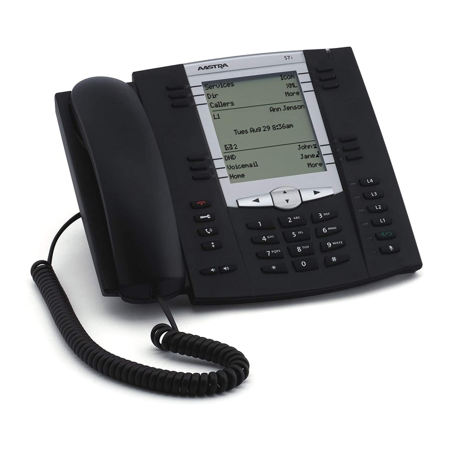
Page 8: Ip Phone Keys
6735i Handset Navigation Keys High Quality Speakerphone 8-Line LCD Screen Message Waiting Lamp Keypad Goodbye Key 4 call appearance lines ... -
Page 9: Key Descriptions
“Adjusting the Volume” page 15 for more information. Line/Call Appearance key - Connects you to a line or call. The Aastra 6735i IP phone supports up to 4 line hold keys. Line 4 Line 4 L4 L4 Line 3 Line 3... - Page 10 Note: For more information about programming keys 1 through 6 to perform specific functions, see the Aastra Model 6735i User Guide. *See the Aastra 6735i User Guide for more information about each of these keys. 41-001370-00 Rev 01 – 07.2011...
-
Page 11: Installation And Setup
Note: 1. The PC jack on the 6735i does not supply inline power onto other network devices. All Ethernet cables used must be minimum category 5/5e straight-through cables, such as the cable provided with your phone. -
Page 12: Connecting To The Network And To Power
Installation and Setup Connecting to the Network and to Power Inline Power Provided If your network provides 802.3af compliant in-line power, the phone is powered through the network. On the top of your phone, connect the Ethernet cable (provided with your phone) into the network port marked with Plug the other end of the Ethernet cable directly into the network jack on the wall. -
Page 13: Connecting A Handset Or Headset
Installation and Setup Ethernet Cables To PoE Network Jack Power Outlet Power injector (if Inline power is not provided) To Network To Phone Jack Note: 1. You should connect the power supply to a surge protector or power bar. All Ethernet cables used must be mini- mum category 5/5e straight-through cables, such as the cable provided with your phone. -
Page 14: Desk Or Wall Installation
Install on the Desk The desk installation for the 6735i IP phone consists of two legs that attach to the back of the phone near the top cor- ners. A total of four different viewing angles allows users to personalize their phone viewing preference. - Page 15 You may wish to purchase a short Ethernet cable from a local supplier for a wall installation. Also, if 802.3af compliant in-line power is not provided on your network, and you are installing the 6735i on a wall using a PoE in-line power injector, you may also wish to use an equivalent flat Ethernet cable rather than the one provided.
- Page 16 Installation and Setup Push the clip in until it snaps into the slot flush with the surface and only the legs on the clip are sticking up. Remove clip, turn 180 degrees, and reinsert clip. Place the handset into the phone’s cradle, inserting the legs on the clip into the square hole on the handset. This allows the handset to rest in the cradle in a vertical position without slipping off when the phone is installed on the wall.
-
Page 17: Inserting The Key Card On Your Phone
Installation and Setup Inserting the Key Card on your Phone This card contains the label identification spaces for 6 programmable keys. Remove the clear plastic lens from the top front panel of the telephone by gently pressing down on the lens and sliding upward. -
Page 18: Accessing Your Options Via The Aastra Web Ui
User. A longer list of options display in the side menu for an Administrator. Reference For more information about using the side menu options in the Aastra Web UI, see the Aastra Model 6735i Phone User Guide. 41-001370-00 Rev 01 – 07.2011... -
Page 19: Other Phone Features
Set Audio The 6735i allows you to use a handset, a headset, or hands free to handle incoming and outgoing calls. The audio mode option provides different combinations of these three methods to provide maximum flexibility in handling calls. There are... -
Page 20: Status Lights (Leds)
Indicates idle line or no call activity Rapid Flash Indicates ringing on the line. Slow Flash Indicates a call is on hold. For more information about the Line/Call Appearance keys, see the Aastra Model 6735i IP Phone User Guide. 41-001370-00 Rev 01 – 07.2011... -
Page 21: Using A Headset With Your Telephone
Using a Headset with your Telephone The 6735i accepts headsets through the modular jack on the back of the phone. Contact your telephone equipment retailer or distributor to purchase a compatible headset. A non-amplified headset is required. Customers should read and observe all safety recommendations contained in headset operating guides when using any headset. -
Page 22: Model M670I And M675I Expansion Modules
Model M670i and M675i Expansion Modules Model M670i and M675i Expansion Modules The 6735i IP phone offers optional M670i and M675i Expansion Modules that attach to the right side of the phone to pro- vide additional softkeys. The 6735i phone supports up to 3 expansion modules (either M675i or M670i) when powered via an optional power adapter. -
Page 23: Installing The Expansion Modules
Model M670i and M675i Expansion Modules Installing the Expansion Modules The M670i and M675i Expansion Modules connect to the right side of a 6735i IP phone via an RJ-45 connector and a con- nector plate. M670i M675i Connector Plate RJ-45 Connector Connecting the Expansion Modules to Your Phone Use the following procedure to connect the Expansion Modules to your 6735i IP phone. -
Page 24: Attaching Multiple Expansion Modules
M670is and an additional 180 softkeys with M675is. You connect the additional modules to the right side of an existing module. The following figure illustrates the addition of multiple M675i modules on the 6735i IP phone. For more information about setting the softkeys, see the Aastra Model 6735i IP Phone User Guide. -
Page 25: Troubleshooting Solutions
There are 6 bottom, state-based softkeys that are programmable up to 20 functions. These keys are located at the center of the phone on either side of the display panel. See the section “Line/Call Appearance Keys” page 16 or refer to your Aastra Model 6735i IP Phone User Guide for more information. 41-001370-00 Rev 01 – 07.2011... -
Page 26: Limited Warranty
Aastra Telecom warrants this product against defects and malfunctions during a one (1) year period from the date of original purchase. If there is a defect or malfunction, Aastra Telecom shall, at its option, and as the exclusive remedy, either repair or replace the telephone set at no charge, if returned within the warranty period. - Page 27 Index Numerics 6735i line settings ............16 lights or LEDs MWI ................16 speaker ............... 16 audio, setting ..............15 status ................16 call timer ................16 M670i ................. 18 Callers List key ..............6 M675i ................. 18 Connecting a Handset or Headset ......9 microphone volume, headset ........
- Page 28 While every effort has been made to ensure accuracy, Aastra Telecom Inc. will not be liable for technical or editorial errors or omissions contained within this documentation. The information contained in this documentation is subject to change without notice.