Table of Contents
Advertisement
Model Number:
5900700
5900702
5900757
5900965
5900539
This manual is available in Spanish. For a copy, contact your Snapper Pro dealer or www.snapperpro.com.
Este manual está disponible en Español. Para obtener una copia, póngase en contacto con
BRIGGS & STRATTON POWER PRODUCTS GROUP, LLC
5375 NORTH MAIN STREET
MUNNSVILLE, NY 13409
800 933 6175
Description
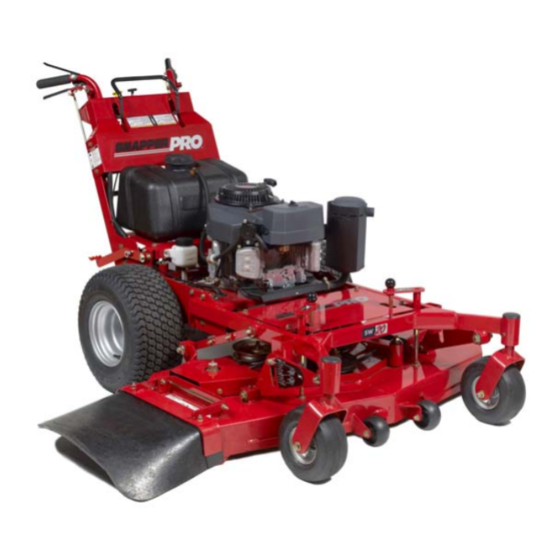
SW20KAV1748, 48" Cut Walk-Behind Mower
SW20KAV1336, 36" Cut Walk-Behind Mower
SW20BV1648, 48" Cut Walk-Behind Mower
SW20KAV1636, 36" Cut Walk-Behind Mower
SW20KAV1536, 36" Cut Walk-Behind Mower
su distribuidor Snapper Pro o www.snapperpro.com.
Operator's Manual
SW20 Series
Walk-Behind Mowers
5101263
Rev H
Advertisement
Table of Contents
Troubleshooting

Related Manuals for Snapper SW20 Series


Summary of Contents for Snapper SW20 Series
- Page 1 5900539 SW20KAV1536, 36” Cut Walk-Behind Mower This manual is available in Spanish. For a copy, contact your Snapper Pro dealer or www.snapperpro.com. Este manual está disponible en Español. Para obtener una copia, póngase en contacto con su distribuidor Snapper Pro o www.snapperpro.com.
- Page 2 Briggs & Stratton Power Products Group, LLC Copyright © 2012 Briggs & Stratton Corporation Milwaukee, WI, USA. All rights reserved. SNAPPER PRO is a trademark of Briggs & Stratton Corporation Milwaukee, WI, USA. Contact Information: Briggs & Stratton Power Products Group, LLC 5375 N.
-
Page 3: Table Of Contents
Table of Contents Operator Safety ............2 Safety Rules and Information ...........2 Safety Decals ..............8 Safety Interlock System ............9 Features & Controls ..........10 Identification Numbers ...........10 Control Functions ............11 Operation ..............13 General ................13 Checks Before Starting ...........13 Starting the Engine ............13 Stopping the Mower ............14 Checking Tire Pressures ..........14 Pushing the Unit by Hand ..........14... -
Page 4: Operator Safety
Safety Rules & Information Operating Safety Congratulations on purchasing a superior-quality piece of lawn and garden equipment. Our products are designed and manufactured to meet or exceed all industry standards for safety. Do not operate this machine unless you have been trained. Reading and understanding this operator’s manual is a way to train yourself. -
Page 5: Slope Operation
Safety Rules & Information Slope Operation You could be seriously injured if you use this unit on too steep of a slope. Using the unit on a slope that is too steep where you do not have adequate footing and unit traction (and control) can cause you to lose control and possibly slip and fall or roll the unit over. - Page 6 Safety Rules & Information Fuel and Maintenance Always disengage all drives, shutoff the engine and remove the key before doing any cleaning, refueling or servicing. Gasoline and its vapors are extremely flammable. Do not smoke while operating or refueling. Do not add fuel while engine is hot or running.
- Page 7 Safety Rules & Information Read these safety rules and follow them closely. Failure to obey these rules could result in loss of control of unit, severe personal injury or death to you, or bystanders, or damage to property or equipment. This mowing deck is capable of amputating hands and feet and throwing objects. The triangle in text signifies important cautions or warnings which must be followed.
- Page 8 Safety Rules & Information 23. Use care when approaching blind corners, shrubs, 6. Keep all movement on the slopes slow and trees or other objects that may obscure vision. gradual. Do not make sudden changes in speed 24. To reduce fire hazard, keep unit free of grass, or direction.
- Page 9 Safety Rules & Information SERVICE AND MAINTENANCE mufflers, and engine to prevent fires. Clean up oil or fuel spillage. To avoid personal injury or property damage, use 10. Let engine cool before storing and do not store extreme care in handling gasoline. Gasoline is near flame.
-
Page 10: Safety Decals
Operator Safety Safety Decals Before operating your unit, read the safety decals. The cautions and warnings are for your safety. To avoid a personal injury or damage to the unit, understand and follow all safety decals. WARNING If any safety decals become worn or damaged, and cannot be read, order replacement decals from your local dealer. -
Page 11: Safety Interlock System
Operator Safety Safety Icons The alert symbol ( ) is used to identity safety information Safety Interlock System about hazards that can result in personal injury. A signal word (DANGER, WARNING, or CAUTION) is used with the This unit is equipped with safety interlock switches. alert symbol to indicate the likelihood and the potential These safety systems are present for your safety, severity of the injury. -
Page 12: Features & Controls
Features and Controls Features and Controls Identification Numbers North American Models Model xxxxxxx xxxxxxxxxxxxxxxxxxxx Serial xxxxxxxxxx CE Models BRIGGS & STRATTON CORP. POWER PRODUCTS GROUP, LLC x.xx MILWAUKEE, WI 53201 USA xxxx 20xx When contacting your authorized dealer for replacement Figure 1. -
Page 13: Control Functions
Features and Controls Figure 2. Control Locations Control Functions The information below briefly describes the function of individual controls. Starting, stopping, driving, and mowing require the combined use of several controls applied in specific sequences. To learn what combination and sequence of controls to use for various tasks see the OPERATION section. Ignition Switch Forward Speed Control Lever The ignition switch starts and stops the engine, it has two... -
Page 14: Throttle Control
Features and Controls Parking Brake Fuel Tank Cap To remove the cap, turn counterclockwise. DISENGAGE Releases the parking brake. ENGAGE Locks the parking brake. Engine Kill / Operator Presence Handles Pull the parking brake handle up to engage the parking These handles are a major factor in the safety interlock brake. -
Page 15: Operation
Operation Operation General Operating Safety Before first time operation: • Be sure to read all information in the Safety and Operation sections before attempting to operate this unit. • Become familiar with all of the controls and how to stop the unit. -
Page 16: Stopping The Mower
Operation Stopping the Mower 1. Gently squeeze both reverse speed control levers evenly to stop the unit. 2. Once the unit is stopped, firmly depress the neutral return pedal to place the transmission in neutral. 3. Disengage the PTO by pushing down on the PTO switch. 3. -
Page 17: Cutting Height Adjustment
Operation Cutting Height Adjustment The cutting height can be adjusted within two different ranges. The lower cutting range is adjustable between 1-1/2” (3,8 cm) and 2-3/4” (6,9 cm). The upper cutting range is adjustable between 2-3/4” (6,9 cm) and 4-1/2” (11,5 cm). - Page 18 Operation To Adjust the Cutting Height: The cutting range must be adjusted to the correct range before the cutting height can be adjusted. The cutting height indicators will help you identify the cutting height. 1. Pull the cutting height adjustment handle (A, Figure 10) up and out of the handle lock position (B) and crank the handle CLOCKWISE to raise the deck to the desired cutting height.
-
Page 19: Driving The Mower
Operation Driving The Mower Before attempting to drive the mower make sure To Slow or Stop Machine you have read the Features and Controls section and 1. Gently squeeze both reverse speed control levers understand the location and function of the controls. evenly to slow the machine. -
Page 20: Mowing
Operation Mowing Before mowing, set the cutting height as described in CUTTING HEIGHT ADJUSTMENT. 1. Engage the parking brake. Make sure the PTO switch is disengaged and the forward speed control lever is in the NEUTRAL position 2. Start the engine (see Starting The Engine). 3. -
Page 21: Mowing Methods
Operation When and How Often to Mow The time of day and condition of the grass greatly affect the results you’ll get when mowing. For the best results, follow these guidelines: 1. Mow when the grass is between three and five inches high. - Page 22 Operation Proper Mulching Mulching consists of a mower deck which cuts and recuts clippings into tiny particles and which then blows them down INTO the lawn. These tiny particles decompose rapidly into by-products your lawn can use. UNDER PROPER CONDITIONS, your mulching mower will virtually eliminate noticeable clippings on the lawn surface.
-
Page 23: Regular Maintenance
Regular Maintenance Regular Maintenance Maintenance Schedule The following schedule should be followed for normal care of your mower and mower deck. You will need to keep a record of your operating time. Determining operating time is easily accomplished by observing the elapsed time recorded by the hour meter. -
Page 24: Checking/Adding Fuel
Regular Maintenance Checking / Adding Fuel WARNING To add fuel: Fuel and its vapors are extremely 1. Remove the fuel cap (E, Figure 12). flammable and explosive. 2. Fill the tank to the bottom of the filler neck. This will allow for fuel expansion. -
Page 25: Lubrication
Regular Maintenance Generally, all moving metal parts should be oiled Lubrication where contact is made with other parts. Keep oil Lubricate the unit at the locations shown in Figures 13 & 14 and grease off belts and pulleys. Remember to wipe as well as the following lubrication points. -
Page 26: Check / Fill Transmission Oil
Regular Maintenance Check / Fill Transmission Oil Oil Type: 20W-50 conventional detergent motor oil. 1. Check the oil level when the unit is cold. Locate the transmission oil reservoirs (A, Figure 15) located on the by the fuel tank. The oil should be up to the “FULL COLD”... -
Page 27: Servicing The Mower Blades
Regular Maintenance Servicing The Mower Blades Removing the Mower Blade CAUTION Avoid injury! Mower blades are sharp. Always wear gloves when handling mower blades or working near blades. 1. To remove the mower blade, use a 1” wrench on the flats of the spindle shaft and remove the mower blade mounting bolt with a 15/16”... - Page 28 Regular Maintenance Sharpening the Mower Blade CAUTION Avoid injury! Mower blades are sharp. • Always wear gloves when handling mower blades or working near blades. • Always wear safety eye protection when grinding. Figure 20. Sharpening the Mower Blade 1. Sharpen the mower blades with grinder, hand file, or A.
-
Page 29: Neutral Adjustment
Regular Maintenance Neutral Adjustment If the unit “creeps” while the forward speed control lever is locked in the NEUTRAL position, then it may be necessary to adjust the linkage rod. NOTE: Perform this adjustment on a hard, level surface such as a concrete floor. 1. -
Page 30: S/N: 2014523388 & Above
Regular Maintenance (2014523388 & Above) To Reduce the Speed of the Faster Wheel: There are three (3) nuts (A, Figure 25) on the linkage rod (B). The first two are to be used together to turn the rod and the third is used to lock the rod in place. 1. -
Page 31: Parking Brake Adjustment
Regular Maintenance 4. Measure the distance between the back of the brake Parking Brake Adjustment pivot link (G) and the front edge of the set collar (F). 1. Disengage the PTO, stop the engine, remove the ignition The measurement should be 1/8” (0,32 cm). If not, key, and engage the parking brake. -
Page 32: Deck Leveling Adjustment
Regular Maintenance Deck Leveling Adjustment To Level the Mower Deck: 1. Park the machine on a flat, level surface. Disengage the PTO, stop the engine and engage the parking brake. Rear tires must be inflated to 15 psi (1,03 bar); front tires to 25 psi (1,72 bar). -
Page 33: Mower Belt Replacement
Regular Maintenance Mower Belt Replacement NOTICE To avoid damaging belts, do NOT pry belts over pulleys. 1. Park the unit on a smooth, level surface such as a concrete floor. Disengage the PTO, engage the parking brake, turn off the engine, and remove the ignition key. 2. - Page 34 Regular Maintenance Mower Belt Replacement (continued...) 5. Remove the old belt and replace with a new one. Make sure the V-side of the belt runs in the pulley grooves (Figure 30). 6. Install the mower drive belt on the PTO pulley, the spindle pulleys and all idler pulleys except the stationary pulley (C, Figure 29).
-
Page 35: Transmission Drive Belt Replacement
Regular Maintenance 4. Loosen the nut on the spring anchor eyebolt (G, Figure Transmission Drive Belt Replacement 33) to release the majority of the belt tension. Use 1. Park the unit on a smooth, level surface such as a caution and remove the nut to completely release the concrete floor. -
Page 36: Reverse Speed Control Levers Adjustment
Regular Maintenance Reverse Speed Control Levers Comfort Adjustment The amount of pressure necessary to depress the Reverse Speed Control Levers (A, Figure 34) can be adjusted to meet the comfort needs of the operator. 1. Disengage the PTO, engage the parking brake and turn off the engine. -
Page 37: Storage
Regular Maintenance Storage WARNING Temporary Storage (30 Days Or Less) Fuel and its vapors are extremely Remember, the fuel tank will still contain some gasoline, so flammable and explosive. never store the unit indoors or in any other area where fuel Fire or explosion can cause severe vapor could travel to any ignition source. -
Page 38: Troubleshooting
Troubleshooting Troubleshooting Troubleshooting Chart WARNING While normal care and regular maintenance will extend the life of your equipment, prolonged or constant use may Remove the ignition key prior to eventually require that service be performed to allow it to performing maintenance on the unit. continue operating properly. -
Page 39: Troubleshooting The Mower Deck
Troubleshooting Mower Troubleshooting Continued. Problem Cause Remedy Transmission release lever(s) 1. Move transmission release lever(s) Engine runs, but mower will in “disengaged” position. to the “engaged” position. not drive. Belt is broken. 2. See Drive Belt Replacement. Drive belt slips. 3. -
Page 40: Troubleshooting Common Cutting Problems
Troubleshooting Troubleshooting Common Cutting Problems Problem Cause Remedy Blades are not sharp. 1. Sharpen your blades. Streaking. Blades are worn down to far. 2. Replace your blades. Engine speed is too slow. 3. Always mow at full throttle. Ground speed is too fast. 4. -
Page 41: Specifications
Specifications Specifications Note: Specifications are correct at time of printing and are subject to change without notice. Model Number 5900700 5900702 5900757 5900965 5900539 ENGINE 17 Gross HP† 13 Gross HP† 16 Gross HP* 16 Gross HP† 15 Gross HP† Kawasaki Kawasaki Briggs &... - Page 43 Notes...
- Page 44 Notes...
-
Page 46: Limited Warranty
ABOUT YOUR WARRANTY We welcome warranty repair and apologize to you for being inconvenienced. Warranty service is available only through SNAPPER PRO Authorized Service Dealers. Most warranty repairs are handled routinely, but sometimes requests for warranty service may not be appropriate. This warranty only covers defects in materials or workmanship. -
Page 47: Your Warranty Rights And Obligations
California, U.S. EPA, and Briggs & Stratton Corporation Emissions Control Warranty Statement September 2012 Your Warranty Rights And Obligations The California Air Resources Board, U.S. EPA, and Briggs & Stratton (B&S) are pleased Owner’s Warranty Responsibilities: to explain the emissions control system warranty on your Model Year 2012--2013 As the engine/equipment owner, you are responsible for the performance of the ... - Page 48 Operator’s Manual SW20 Series Walk-Behind Mowers BRIGGS & STRATTON POWER PRODUCTS GROUP, LLC 5375 NORTH MAIN STREET MUNNSVILLE, NY 13409 800 933 6175...