Table of Contents
Advertisement
Quick Links
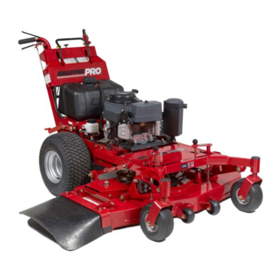
OPERATOR'S
MANUAL
SW20Series
Walk-BehindMowers
Model Humber:
5900700
5900702
Description
SW20KAV1748, 17HP Kawasaki, 48" Cut Walk-Behind Mower
SW20KAV133B, 13HP Kawasaki, 36" Cut Walk-Behind Mower
Briggs & Stratton Power ProductsGroup
5375 North Main Street
Munnsville, NY 13409
800-933-6175
5101263
RevisionIR
Rev.Date:11/2007
TP 100-7359-1R-WD-SP
Advertisement
Table of Contents
Troubleshooting

Related Manuals for Snapper SW20 Series


Summary of Contents for Snapper SW20 Series
- Page 1 OPERATOR'S MANUAL SW20Series Walk-BehindMowers Model Humber: Description 5900700 SW20KAV1748, 17HP Kawasaki, 48" Cut Walk-Behind Mower 5900702 SW20KAV133B, 13HP Kawasaki, 36" Cut Walk-Behind Mower Briggs & Stratton Power ProductsGroup 5101263 5375 North Main Street RevisionIR Munnsville, NY 13409 Rev.Date:11/2007 800-933-6175 TP 100-7359-1R-WD-SP...
- Page 2 Briggs & Stratton Power Products Group Copyright {© 2008 Briggs & Stratton Corporation Milwaukee, WI, USA. All rights reserved. The Snapper Pro logo is a trademark of Briggs & Stratton Corporation Milwaukee, WI, USA. Contact Information: Briggs & Stratton Power Products Group 5375 N.
-
Page 3: Table Of Contents
Table of Contents Operator Safety ............. Safety Rules and Information...........2 Safety Decals..............8 Safety InterlockSystem............9 Features & Controls..........Identification Numbers ...........10 Control Functions ............11 Operation ............General ................13 Checks Before Starting ..........13 Checking Tire Pressures..........14 Pushing the Unit by Hand..........14 Cutting Height Adjustment ..........15 Starting the Engine ............17 Stopping the Mower ............17... -
Page 4: Operator Safety
$a{etyRules & Ifl{ormUofl OperatingSafety Congratulations on purchasing a superior-quality piece of lawn and garden equipment. Our products are designed and manufactured to meet or exceed all industry standards for safety. Do not operatethis machine unless you have been trained. Readingand understanding this operator's manual is a way to train yourself. - Page 5 SafetyRules & Iflformatiofl Slope Operation You could be seriously injured if you use this unit on too steep of a slope. Using the unit on a slope that is too steep where you do not have adequate footing and unit traction (and control) can cause you to lose control and possibly slip and fall or roll the unit over.
- Page 6 Sa{etyRules & Ifl{ormUofl Fueland Maintenance Always disengageall drives, shutoff the engine and remove the key before doing any cleaning, refueling or servicing. Gasoline and its vapors are extremely flammable. Do not smoke while operating or refueling. Do not add fuel while engine is hot or running.
- Page 7 SsfetyRules & information Readthese safety rules and follow them closely. Failureto obey these rules could result in loss of control of unit, severe personal injury or death to you, or bystanders, or damage to property or equipment. This mowing deck is capable of amputating hands and feet and throwin_ The triangle _ in text signifies important cautions...
- Page 8 SafetyRules & information Do Not spark arrester. It is a violation of California Public ResourceCode Section 4442 to use or operate the 1. Avoid starting, stopping, or turning on a slope. If tires engine on or near any forest-covered, brush-covered, or lose traction (i.e.
- Page 9 SafetyRules & Iflformtiofl SERVICE AND MAINTENANCE Repair, if necessary,before restarting. 12. Park machine on level ground. Never allow untrained Toavoid personal injuryor property damaqe, use extreme personnel to service machine. care in handling gasoline. Gasoline is extremely flammable 13. Use jack stands to support components when required. and the vaporsare explosive.
-
Page 10: Safety Decals
Operator Safety Safety Decals This unithasbeendesignedandmanufactured to provide youwith the safetyandreliabilityyouwouldexpectfrom an industryleaderin outdoorpowerequipment m anufacturing. Although reading this manual and the safety instructions it contains will provide you with the necessary basic knowledge to operatethis equipment safely and effectively, we have placed several safety labels on the unit to remind you of this important information while you are operating your unit. -
Page 11: Safety Interlocksystem
Operator Safety Safety icons The alert symbol '_ is used to identity safety information about hazards that can result in personal injury. A signal Safetyinterlock System word (DANGER,WARNING, or CAUTION)is used with the alert symbol to indicate the likelihood and the potential this unit is equipped with safety interlockswitches. -
Page 12: Features & Controls
Operator Safety Featuresand Controls Identification N.rnbers When contactingyourauthorized dealer for replacement parts, service, or informationyou MUST have these numbers. Record your part number, serial number and engine serial numbers in the space provided on the inside front cover for easy access. These numbers can be found in the locations shown in Figure 1. -
Page 13: Control Functions
,Features andControls Figure 2, Control Locations Control Functions Theinformation below briefly describes the tiJnction of individual controls. Starting, stopping, driving, and mowing require the combined use of several controls applied in specific sequences. Tolearn what combination and sequence of controls to use for various tasks see the OPERATION section. - Page 14 Features & Centrols ParkingBrake Fuel Tank Cap To remove the cap, turn counterclockwise. DISENGAGE Releasesthe parking brake. Engine Kill / Operator Presence Handles ENGAGE Locks the parking brake. These handles are a major factor in the safety interlock system of the mower. Both handles are tied together so Pull the parking brake handle up to engage the parking depressing one handle depresses both.
-
Page 15: Operation
Operatiofl Operation AWARNING GeneralOperatingSafety Before first time operation: Never operate on slopesgreater than 15° which is a ,. Be sure to read all information in the Safety and rise of 5.4 feet (1,6 m) vertically in 20 feet (607 cm) Operationsections before attempting to operate this horizontally. -
Page 16: Checking Tire Pressures
Operation CheckTire Pressures Tire pressure should be checked periodically, and maintained at the levels shown in the chart. Note that these pressures may differ slightly from the "Max Inflation" stamped on the side-wall of the tires. The pressures shown provide proper traction, improve cut quality, and extend tire life. -
Page 17: Cuttingheightadjustment
Operatiofl CuttingHeightAdjustment The cutting height can be adjusted within two different ranges. The lower cutting range is adjustable between 1-1/2" (3,8 cm) and 2-3/4" (6,9 cm). The upper cutting range is adjustable between 2-3/4" (6,9 cm) and 4-1/2" (11,5 cm). Before adjusting the cutting height, you must first determine the averagecutting height. - Page 18 ,Operation ToAdjust the gutting Height: The cutting range must be adjusted to the correct range before the cutting height can be adjusted. The cutting height indicators will help you identify the cutting height. 1. Pull the cutting height adjustment handle (A, Figure 10) up and out of the handle lock position (B) and crank the handle CLOCKWISE to raise the deck to the desired cutting height.
-
Page 19: Starting The Engine
Operation Starting the Engine Stopping the Mower 1. Gently squeeze both reverse speed control levers evenly AWARNING to stop the unit. 2. Oncethe unit is stopped, firmly depress the neutral if you de net understandhow a specificcontrol return pedal to placethe transmission in neutral. functions, or havenot yet thoroughlyread the 3. -
Page 20: Drivingthe Mower
Operation DrivingThe Mower NOTE: Before attempting to drive the mower make sure you have read the Featuresand Controls section and understand the location and function of the controls. The hydrostatic transmission has an infinite number of speeds between full speed forward and reverse, with the faster speeds being achieved by moving the forward speed control lever and reverse speed control levers farthest in the direction of travel. - Page 21 Operatiofl TO TURN MACHINE NOTE"ALWAYSREDUCE SPEEDIN A TURN To make a left-hand turn (See Figure 13): Gently squeezethe left hand reverse speed control lever (A, Figure 13) A sharp or gentle turn is determined by the amount of force applied to the steering control lever Figure 13 Left Turn Travel A Left Hand Reverse Speed Control Lever To make a right-handturn (See Figure 14):...
-
Page 22: Mowing
Operation Mowing Before mowing, set the cutting height as described in CUTTINGHEIGHTADJUSTMENT. 1. Engagethe parking brake. Make sure the PTOswitch is disengaged and the forward speed control lever is in the NEUTRALposition 2. Start the engine (see Starting The Engine). 3. -
Page 23: Mowing Methods
Operatiofl When and How Often to Mow The time of day and condition of the grass greatly affect the results you'll get when mowing. For the best results, follow these guidelines: 1. Mow when the grass is between three and five inches high. - Page 24 Operation Proper Mulching Mulching consists of a mower deck which cuts and recuts clippings into tiny particles and which then blows them down INTOthe lawn. Thesetiny particles decompose rapidly into by-products your lawn can use. UNDERPROPER CONDITIONS, y our mulching mower will virtually eliminate noticeable clippings on the lawn surface.
-
Page 25: Regular Maintenance
Regular Maintenance Regular Maintenance Maintenance Schedule The following schedule should be followed for normal care of your mower and mower deck. You will need to keepa record of your operating time. Determining operating time is easily accomplished by observing the elapsed time recorded by the hour meter. -
Page 26: Checking/Adding Fuel
Regular Maintenance Checking/Adding Fuel , WARNING To add fuel: Gasolineis highly flammable and must be handled 1. Removethe fuel cap (E, Figure 18). with care. Never fill the tank when the engine is still 2. Fill the tankto the bottom of the filler neck. Thiswill hot from recent operation. -
Page 27: Lubrication
Regular Maintenance Generally,all moving metal parts should be oiled where Lubrication contact is made with other parts. Keep oil and grease off Lubricate the unit at the locations shown in Figures 19 as belts and pulleys. Rememberto wipe fittings and surfaces well as the following lubrication points. -
Page 28: Check/Fill Transmission Oil
Regular Maintenance Check/ Fiii Transmission Oil Oil Type: 20W-50 conventional detergent motor oil. 1. Checkthe oil level when the unit is cold. Locatethe transmission oil reservoirs (A, Figure 21) locatedon the by the fuel tank. The oil should be up to the 'FULL COLD"mark (B). -
Page 29: Servicing The Mower Blades
Regular Maintenance Servicing The Mower Blades Removing the Mower Blade , ,CAUTION Avoid injury! Mower blades are sharp. * Always wear gloves when handling mower blades or working near blades. 1. To remove the mower blade, use a 1" wrench on the flats of the spindle shaft and remove the mower blade mounting bolt with a 15/16"... - Page 30 Regular Maintenance Sharpening the Mower Blade , CAUTION Avoid injury! Mower blades are sharp. ,, Alwayswear gloves when handling the mower blades. ,, Alwayswear safety eye protectionwhen grinding. ® 1. Sharpen the mower blades with grinder, hand file. or Figure 26, Sharpening the Mower Blade electric blade sharpener.
-
Page 31: Neutral Adjustment
Regular Maintenance Nentral Adjustment Iftheunit"creeps"wHlethe forwardspeedcontrolleveris locked inthe NEUTRAL p osition,thenit maybenecessary to adjustthe linkage rod. NOTE:Perform this adjustment on a hard, level surface such as a concrete floon 1. Disengagethe PTO,engage the parking brake and turn off the engine. 2. -
Page 32: Parkingbrakeadjustment
3. With the parking brake engaged, measure the if this dues not correctthe braking problem, see yuur compressed spring length of the brake spring. The Snapper Pru dealer. spring should be 2-3/8" (6,03 cm) when compressed. If not, position the lock nut until the measurement equals 2-3/8"... -
Page 33: Deck Leveling Adjustment
RegWr MaJflteflaflce Deck Leveling Adjustment ToLeveltheMowerDeck: 1. Park the machine on a flat. level surface. Disengagethe PTO,stop the engine and engage the parking brake. Reartires must be inflated to 15 psi (1,03 bar); front tires to 25 psi (1,72 bar). 2. -
Page 34: Mower Belt Replacement
RegWr Maintenance Mower Belt Replacement ® NOTICE To avoid dan]agingbelts, DONOT PRY BELTSOVER PULLEYS. 1. Park the unit on a smooth, level surface such as a concrete floor. Disengagethe PTO,engage the parking brake, turn off the engine, and remove the ignition key. 2. - Page 35 RegWr MsJflteflsflce ® ® Figure 35, Mower Deck Belt Routing A. Mower Drive Belt B, Adjustable Idler Pulley C. Spindle Pulley D. Stationary Idler Pulley E, 36" Mower Deck £ 48"Mower Deck Figure 36, Mower Belt TensionerSpring Measurement (36" Models) A.
-
Page 36: Transmission Drive Belt Replacement
Regular Maintenance Transmission Drive Belt Replacement 5. Removethe old belt and replace it with the new one. Make sure the V-side of the belt runs in the grooves of 1. Park the unit on a smooth, level surface such as a the crankshaft pulley and transmission pulleys (B &... -
Page 37: Reversespeed Control Levers Adjustment
RegWr Maintenance ReverseSpeed Control LeversComfort Adjustment The amount of pressure necessary to depress the Reverse Speed Control Levers (A, Figure 39) can be adjusted to meet the comfort needs of the operator. 1. Disengagethe PTO,engage the parking brake and turn off the engine. -
Page 38: Storage
RegWr MaJflteflaflce Storage AWARNING TemporaryStorage (38 DaysOr Less) Never store the unit, with gasoline in engine or fuel Remember,the fuel tank will still contain some gasoline, so tank, in a heated shelter or in enclosed, poorly never store the unit indoors or in any other area where fuel ventilated enclosures. -
Page 39: Troubleshooting
Troubleshooting Troubleshooting Troubleshooting Chart AWARNING While normal care and regular maintenancewill extend the To avoid seriousinjury, perform maintenance on the life of your equipment, prolonged or constant use may unit onlywhen the engine is stoppedand the parking eventually require that service be performed to allow it to brake engaged. -
Page 40: Troubleshooting The Mower Deck
Troubleshootiflg Mower Trouh/eshppting Continued, Problem Cause Remedy Eegille rues, but mower will Transmission releaselever(s) 1. Move transmissionreleaselever(s) not drive, in "disengaged" position, to the "engaged" position. Belt is broken. 2. See Drive Belt Replacement. Drive belt slips. 3. See problem and cause below. Brake is not fully released. -
Page 41: Troubleshooting Common Cutting Problems
Troubleshootiflg Troubleshooting Common Cutting Problems Problem Cause Remedy Streaking. Blades are not sharp. 1. Sharpen your blades. Blades are worn down to far. 2. Replaceyour blades. Engine speed is too slow. 3. Always mow at full throttle. 4. Slow down. Ground speed is too fast. -
Page 42: Specifications
$pecHicaUons Specifications NOTE:Specifications are correct at time of printing and are subject to change without notice, *Actual sustained equipment horsepower likely to be lower due to operating limitations and environmental factors. TRANSMISSIONS: ENGINE: HvdroGear ZH-KMBB-3A5A-1LLX(LH) 13 HP* Kawasaki HvdroGear ZH-GIVIBB-3A5A-1LLX (RH) Make Kawasaki Model... -
Page 43: Slope Identification Guide
ALIGN THiS EDGE WiTH A VERTICAL SURFACE (TREE, POLE, FENCE POST, BUiLDiNG, ETC) r" r==r, ==,= m=,_ "4 __ _.=-- _$" .""o • o'=o ==.= = -_ _. _. _. • ,< _ $'<o o<_. °... - Page 44 Notes...
- Page 45 Notes...
- Page 46 Pro' obligation under this limited warranty is, at Snapper Pro' option, to repair or replace any part or parts of the mower, which, in the judgment of Snapper Pro, are found to be defective and covered by this limited warranty. An authorized Snapper Pro dealer will repair or replace the defective part or parts, at the dealer's place of business, at no charge for the labor or parts.
- Page 47 oOPERA TOR'S MANUAL SW20Series Walk-BehindMowers CommonService Parts: Product S pecifications: ENGINE: BELTS AND BLADES: TRACTOR 13 HP Kawasaki Pump Drive BeJt 5021770 Make Kawasaki Medel FH381V 36" MOWERDECK Oil Capacity 1.9 US qt. ( 1.8 L) w/Filter Deck Drive Belt 5101313 17 HP Kawasaki Mower Blade...