Table of Contents
Advertisement
Model Number:
5900700
5900702
Briggs & Stratton Power Products Group
5375 North Main Street
Munnsville, NY 13409
800-933-6175
OPERATOR'S
MANUAL
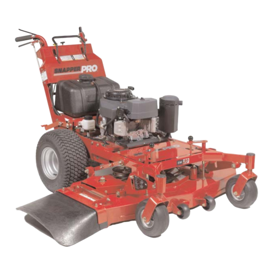
SW20 Series
Walk-Behind Mowers
Description
SW20KAV1748, 17HP Kawasaki, 48" Cut Walk-Behind Mower
SW20KAV1336, 13HP Kawasaki, 36" Cut Walk-Behind Mower
5101263
Revision IR
Rev. Date: 11/2007
TP 100-7359-IR-WD-SP
Advertisement
Table of Contents
Troubleshooting

Related Manuals for Snapper 5900700


Summary of Contents for Snapper 5900700
- Page 1 Model Number: 5900700 5900702 Briggs & Stratton Power Products Group 5375 North Main Street Munnsville, NY 13409 800-933-6175 OPERATOR’S MANUAL SW20 Series Walk-Behind Mowers Description SW20KAV1748, 17HP Kawasaki, 48” Cut Walk-Behind Mower SW20KAV1336, 13HP Kawasaki, 36” Cut Walk-Behind Mower 5101263 Revision IR Rev.
- Page 2 Snapper Pro product. We’re pleased that you’ve placed your confidence in the Snapper Pro brand. When operated and maintained according to the instructions in this manual, your Snapper Pro product will provide many years of dependable service.
-
Page 3: Table Of Contents
Table of Contents Operator Safety ...2 Safety Rules and Information ...2 Safety Decals ...8 Safety Interlock System...9 Features & Controls ...10 Identification Numbers ...10 Control Functions ...11 Operation ...13 General ...13 Checks Before Starting ...13 Checking Tire Pressures ...14 Pushing the Unit by Hand...14 Cutting Height Adjustment...15 Starting the Engine ...17 Stopping the Mower ...17... -
Page 4: Operator Safety
Safety Rules & Information Read the Manual The operator’s manual contains important safety information you need to be aware of BEFORE you operate your unit as well as DURING operation. Safe operating techniques, an explanation of the product’s features and controls, and maintenance information is included to help you get the most out of your equipment investment. - Page 5 Thrown Objects This unit has spinning mower blades. These blades can pick up and throw debris that could seriously injure a bystander. Be sure to clean up the area to be mowed and remove objects that could be thrown by the blade BEFORE you start mowing.
- Page 6 Safety Rules & Information Enclosed Areas Only operate this unit outdoors and away from unventilated areas such as inside garages or enclosed trailers. The engine emits poisonous carbon monoxide gas and prolonged exposure in an enclosed area can result in serious injury or death. Fuel and Maintenance Always disengage all drives, shutoff the engine and remove the key before doing any cleaning, refueling or servicing.
- Page 7 Read these safety rules and follow them closely. Failure to obey these rules could result in loss of control of unit, severe personal injury or death to you, or bystanders, or damage to property or equipment. This mowing deck is capable of amputating hands and feet and throwing objects.
- Page 8 Safety Rules & Information spark arrester. It is a violation of California Public Resource Code Section 4442 to use or operate the engine on or near any forest-covered, brush-covered, or grass-covered land unless the exhaust system is equipped with a spark arrester meeting any applicable local or state laws.
- Page 9 SERVICE AND MAINTENANCE To avoid personal injury or property damage, use extreme care in handling gasoline. Gasoline is extremely flammable and the vapors are explosive. Safe Handling of Gasoline 1. Extinguish all cigarettes, cigars, pipes, and other sources of ignition. 2.
-
Page 10: Safety Decals
Operator Safety Safety Decals This unit has been designed and manufactured to provide you with the safety and reliability you would expect from an industry leader in outdoor power equipment manufacturing. Although reading this manual and the safety instructions it contains will provide you with the necessary basic knowledge to operate this equipment safely and effectively, we have placed several safety labels on the unit to remind... -
Page 11: Safety Interlock System
Safety Interlock System This unit is equipped with safety interlock switches. These safety systems are present for your safety, do not attempt to bypass safety switches, and never tamper with safety devices. Check their operation regularly. Operational SAFETY Checks Test 1 — Engine should NOT crank if: •... -
Page 12: Features & Controls
Operator Safety Features and Controls Identification Numbers When contacting your authorized dealer for replacement parts, service, or information you MUST have these numbers. Record your part number, serial number and engine serial numbers in the space provided on the inside front cover for easy access. -
Page 13: Control Functions
Figure 2. Control Locations Control Functions The information below briefly describes the function of individual controls. Starting, stopping, driving, and mowing require the combined use of several controls applied in specific sequences. To learn what combination and sequence of controls to use for various tasks see the OPERATION section. - Page 14 Features & Controls Parking Brake DISENGAGE Releases the parking brake. ENGAGE Locks the parking brake. Pull the parking brake handle up to engage the parking brake. Push the parking brake handle down to disengage the parking brake. NOTE: To start the unit the parking brake must be engaged.
-
Page 15: Operation
Operation General Operating Safety Before first time operation: • Be sure to read all information in the Safety and Operation sections before attempting to operate this unit. • Become familiar with all of the controls and how to stop the unit. •... -
Page 16: Checking Tire Pressures
Operation Check Tire Pressures Tire pressure should be checked periodically, and maintained at the levels shown in the chart. Note that these pressures may differ slightly from the “Max Inflation” stamped on the side-wall of the tires. The pressures shown provide proper traction, improve cut quality, and extend tire life. -
Page 17: Cutting Height Adjustment
Cutting Height Adjustment The cutting height can be adjusted within two different ranges. The lower cutting range is adjustable between 1-1/2” (3,8 cm) and 2-3/4” (6,9 cm). The upper cutting range is adjustable between 2-3/4” (6,9 cm) and 4-1/2” (11,5 cm). Before adjusting the cutting height, you must first determine the average cutting height. - Page 18 Operation To Adjust the Cutting Height: The cutting range must be adjusted to the correct range before the cutting height can be adjusted. The cutting height indicators will help you identify the cutting height. 1. Pull the cutting height adjustment handle (A, Figure 10) up and out of the handle lock position (B) and crank the handle CLOCKWISE to raise the deck to the desired cutting height.
-
Page 19: Starting The Engine
Starting the Engine WARNING If you do not understand how a specific control functions, or have not yet thoroughly read the FEATURES & CONTROLS section, do so now. Do NOT attempt to operate the unit without first becoming familiar with the location and function of ALL controls. -
Page 20: Driving The Mower
Operation Driving The Mower NOTE: Before attempting to drive the mower make sure you have read the Features and Controls section and understand the location and function of the controls. The hydrostatic transmission has an infinite number of speeds between full speed forward and reverse, with the faster speeds being achieved by moving the forward speed control lever and reverse speed control levers farthest in the direction of travel. - Page 21 TO TURN MACHINE NOTE: ALWAYS REDUCE SPEED IN A TURN. To make a left-hand turn (See Figure 13): Gently squeeze the left hand reverse speed control lever (A, Figure 13). A sharp or gentle turn is determined by the amount of force applied to the steering control lever. To make a right-hand turn (See Figure 14): Gently squeeze the right hand reverse speed control lever (A, Figure 14).
-
Page 22: Mowing
Operation Mowing Before mowing, set the cutting height as described in CUTTING HEIGHT ADJUSTMENT. 1. Engage the parking brake. Make sure the PTO switch is disengaged and the forward speed control lever is in the NEUTRAL position 2. Start the engine (see Starting The Engine ). 3. -
Page 23: Mowing Methods
When and How Often to Mow The time of day and condition of the grass greatly affect the results you’ll get when mowing. For the best results, follow these guidelines: 1. Mow when the grass is between three and five inches high. -
Page 24: Attaching A Trailer
Operation Proper Mulching Mulching consists of a mower deck which cuts and recuts clippings into tiny particles and which then blows them down INTO the lawn. These tiny particles decompose rapidly into by-products your lawn can use. UNDER PROPER CONDITIONS, your mulching mower will virtually eliminate noticeable clippings on the lawn surface. -
Page 25: Regular Maintenance
Regular Maintenance Maintenance Schedule The following schedule should be followed for normal care of your mower and mower deck. You will need to keep a record of your operating time. Determining operating time is easily accomplished by observing the elapsed time recorded by the hour meter. -
Page 26: Checking/Adding Fuel
Regular Maintenance Checking / Adding Fuel To add fuel: 1. Remove the fuel cap (E, Figure 18). 2. Fill the tank to the bottom of the filler neck. This will allow for fuel expansion. NOTE: Do not overfill. Refer to your engine manual for specific fuel recommendations. -
Page 27: Lubrication
Lubrication Lubricate the unit at the locations shown in Figures 19 as well as the following lubrication points. Grease: • front caster wheel axles & yokes • deck lift pivot blocks • mower deck spindles • mower deck idler arm Use grease fittings when present. -
Page 28: Check / Fill Transmission Oil
Regular Maintenance Check / Fill Transmission Oil Oil Type: 20W-50 conventional detergent motor oil. 1. Check the oil level when the unit is cold. Locate the transmission oil reservoirs (A, Figure 21) located on the by the fuel tank. The oil should be up to the “FULL COLD”... -
Page 29: Servicing The Mower Blades
Servicing The Mower Blades Removing the Mower Blade CAUTION Avoid injury! Mower blades are sharp. • Always wear gloves when handling mower blades or working near blades. 1. To remove the mower blade, use a 1” wrench on the flats of the spindle shaft and remove the mower blade mounting bolt with a 15/16”... - Page 30 Regular Maintenance Sharpening the Mower Blade CAUTION Avoid injury! Mower blades are sharp. • Always wear gloves when handling the mower blades. • Always wear safety eye protection when grinding. 1. Sharpen the mower blades with grinder, hand file, or electric blade sharpener.
-
Page 31: Neutral Adjustment
Neutral Adjustment If the unit “creeps” while the forward speed control lever is locked in the NEUTRAL position, then it may be necessary to adjust the linkage rod. NOTE: Perform this adjustment on a hard, level surface such as a concrete floor. 1. -
Page 32: Parking Brake Adjustment
(G) and the front edge of the set collar (F). The measurement should be 1/8” (0,32 cm). If not, position the set collar until the measurement equals 1/8” (0,32 cm). If this does not correct the braking problem, see your Snapper Pro dealer. www.SnapperPro.com... -
Page 33: Deck Leveling Adjustment
Deck Leveling Adjustment To Level the Mower Deck: 1. Park the machine on a flat, level surface. Disengage the PTO, stop the engine and engage the parking brake. Rear tires must be inflated to 15 psi (1,03 bar); front tires to 25 psi (1,72 bar). 2. -
Page 34: Mower Belt Replacement
Regular Maintenance Mower Belt Replacement NOTICE To avoid damaging belts, DO NOT PRY BELTS OVER PULLEYS. 1. Park the unit on a smooth, level surface such as a concrete floor. Disengage the PTO, engage the parking brake, turn off the engine, and remove the ignition key. 2. - Page 35 Figure 35. Mower Deck Belt Routing A. Mower Drive Belt B. Adjustable Idler Pulley C. Spindle Pulley D. Stationary Idler Pulley E. 36” Mower Deck F. 48” Mower Deck Figure 36. Mower Belt Tensioner Spring Measurement (36” Models) A. Anchor Eyebolt B.
-
Page 36: Transmission Drive Belt Replacement
Regular Maintenance Transmission Drive Belt Replacement 1. Park the unit on a smooth, level surface such as a concrete floor. Disengage the PTO, engage the parking brake, turn off the engine, and remove the ignition key. 2. Remove the PTO drive belt (see MOWER BELT REPLACEMENT for removal instructions). -
Page 37: Reverse Speed Control Levers Adjustment
Reverse Speed Control Levers Comfort Adjustment The amount of pressure necessary to depress the Reverse Speed Control Levers (A, Figure 39) can be adjusted to meet the comfort needs of the operator. 1. Disengage the PTO, engage the parking brake and turn off the engine. -
Page 38: Storage
Regular Maintenance Storage Temporary Storage (30 Days Or Less) Remember, the fuel tank will still contain some gasoline, so never store the unit indoors or in any other area where fuel vapor could travel to any ignition source. Fuel vapor is also toxic if inhaled, so never store the unit in any structure used for human or animal habitation. -
Page 39: Troubleshooting
Troubleshooting Troubleshooting Chart While normal care and regular maintenance will extend the life of your equipment, prolonged or constant use may eventually require that service be performed to allow it to continue operating properly. The troubleshooting guide below lists the most common problems, their causes and remedies. -
Page 40: Troubleshooting The Mower Deck
Troubleshooting Mower Troubleshooting Continued. Problem Engine runs, but mower will not drive. Mower drive belt slips. Brake will not hold. Mower steers or handles poorly. Troubleshooting the Mower Deck Problem Mower Deck will not raise. Engine stalls easily with mower deck engaged. Excessive mower deck vibration. -
Page 41: Troubleshooting Common Cutting Problems
Troubleshooting Common Cutting Problems Problem Streaking. Scalping. Stepped Cutting. Uneven Cutting. Stingers. Cause Blades are not sharp. Blades are worn down to far. Engine speed is too slow. Ground speed is too fast. Deck is plugged with grass Not overlapping cutting rows enough. -
Page 42: Specifications
Specifications Specifications NOTE: Specifications are correct at time of printing and are subject to change without notice. *Actual sustained equipment horsepower likely to be lower due to operating limitations and environmental factors. ENGINE: 13 HP* Kawasaki Make Kawasaki Model FH381V Horsepower 13 @ 3600 rpm Displacement... -
Page 43: Slope Identification Guide
ALIGN THIS EDGE WITH A VERTICAL SURFACE (TREE, POLE, FENCE POST, BUILDING, ETC) - Page 44 Notes...
- Page 45 Notes...
- Page 47 Snapper Pro dealer during the warranty period. Snapper Pro' obligation under this limited warranty is, at Snapper Pro' option, to repair or replace any part or parts of the mower, which, in the judgment of Snapper Pro, are found to be defective and covered by this limited warranty.
-
Page 48: Product Specifications
Product Specifications: ENGINE: 13 HP Kawasaki Make Kawasaki Model FH381V Oil Capacity 1.9 US qt. ( 1.8 L) w/ Filter 17 HP Kawasaki Make Kawasaki Model FH541V Oil Capacity 1.9 US qt. ( 1.8 L) w/ Filter CHASSIS: Fuel Tank Capacity: 5.5 Gallons (20,82 L) Rear Wheels Tire Size: 18 x 6.50 - 8 (36”...